
Static Thrust Test Stand
HARRY CORDES
Every electric modeler knows it's important to "keep it light" to offset the weight of the heavy motor-and-battery combination. A better (and more fundamental) rule might be "maximize the thrust-to-weight ratio!" This rule still calls for keeping things light, but it also emphasizes the thrust side of the equation. If we're going to tolerate a heavier power train, at least we can ask it to deliver as much thrust as possible.
There are many techniques and materials that can be used to keep things light—a lot of modelers have developed their use into a fine art. But how do you select power-train components to maximize thrust? It's not an easy task. Most catalogs and sales brochures are woefully short of accurate specifications or ratings. We're left with the "buy-it-and-try-it" method, tempered with judgment from experience.
This is where static-thrust tests can help. They provide a better idea of an airplane's potential performance before you build or fly it. Static-thrust tests also reduce the number of "cut-and-try" tests in the field. Static tests can be run in the shop—day or night, or when the weather prevents flying.
Test-stand concept
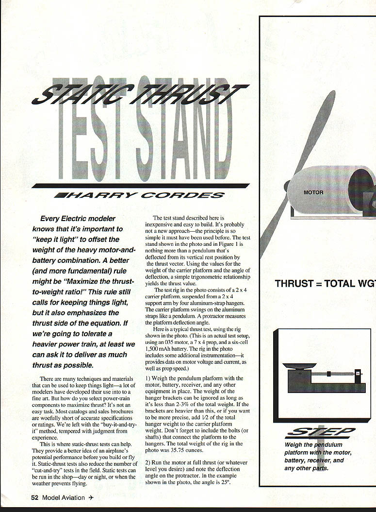
The test stand described here is inexpensive and easy to build. It's probably not a new approach—the principle is so simple it must have been used before. The test stand shown in the photo and in Figure 1 is nothing more than a pendulum that's deflected from its vertical rest position by the thrust vector. Using the values for the weight of the carrier platform and the angle of deflection, a simple trigonometric relationship yields the thrust value.
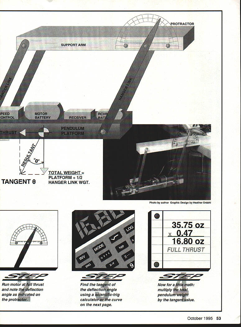
The test rig in the photo consists of a 2x4 carrier platform, suspended from a 2x4 support arm by four aluminum-strap hangers. The carrier platform swings on the aluminum straps like a pendulum. A protractor measures the platform deflection angle.
Typical test setup
Here is a typical thrust test, using the rig shown in the photo. (This is an actual test setup, using a .035 motor, a 7×4 prop, and a six-cell 1,500 mAh battery.) The rig in the photo includes some additional instrumentation—it provides data on motor voltage and current, as well as prop speed.
- Weigh the pendulum platform with the motor, battery, receiver, and any other equipment in place. The weight of the hanger brackets can be ignored as long as it's less than 2–3% of the total weight. If the brackets are heavier than this, or if you want to be more precise, add one-half of the total hanger weight to the carrier-platform weight. Don't forget to include the bolts (or shafts) that connect the platform to the hangers. The total weight of the rig in the photo was 35.75 ounces.
- Run the motor at full thrust (or whatever level you desire) and note the deflection angle on the protractor. In the example shown in the photo, the angle is 25°.
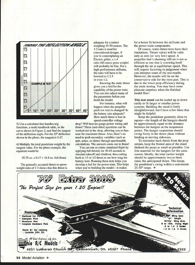
- Use a calculator that handles trig functions or a math-handbook table (see the curve shown in Figure 2). Find the tangent of the deflection angle. For a 25° deflection the tangent is 0.47.
- Multiply the total pendulum weight by the tangent value. In the photo example the equation is:
35.75 oz × 0.47 = 16.80 oz full thrust.
A generally accepted thrust-to-gross-weight ratio of 1:3 shows this thrust is adequate for a trainer weighing 45–50 ounces. The 1:3 ratio is used for conventional designs. If you’re contemplating an electric glider, a 1:4 ratio (for a 60-ounce gross weight) will probably be fine. For a high-performance airframe the ratio will be higher.
Knowing static thrust gives a feel for the capability of the power train and can also allow you to adjust parameters before building the model. For instance:
- What will happen if the propeller pitch or size is changed?
- Will the battery size be adequate?
- How much thrust is lost to speed-controller voltage drop?
- Will heavier-gauge power wiring add thrust?
Other questions can be worked out in the shop, allowing fine-tuning for maximum thrust.
Also, there’s no need to push secondary variables (such as rpm, amps, ohms) through questionable calculations — the answers come out in thrust. You can run an entire simulated flight by applying full throttle for 30–45 seconds to simulate takeoff and climbout, then cutting back to one-third to one-half thrust to see how long the battery lasts. Running tests helps develop a feel for the power train and helps you build the model; it makes a better fit between airframe and power-train components.
Limitations
Of course static-thrust tests have limitations. Thrust values are valid at zero or very low speed only—a propeller that’s merely churning in still air is not as efficient as when it is moving through the air at its equilibrium speed. You must factor in judgement when interpreting some test results. However, the results will generally be conservative due in part to lower prop efficiency during static testing, and you may have some pleasant surprises when the finished model flies.
Building the stand and tips
The test stand can be scaled up or down easily to fit larger or smaller models. Building the stand is fairly straightforward, but here are a few hints that might be helpful:
- Keep the pendulum geometry close to square—the length of the hangers should be approximately equal to the distance between the hangers at the suspension points. The hanger suspension should swing freely in the thrust plane without binding or moving sideways.
- To minimize back-thrust from the propstream, keep the front area of the stand (behind the prop) as small as possible. Use thin material for the hangers for the same reason.
- Ideally, the total carrier weight should be approximately two to three times the anticipated thrust. This keeps the pendulum's swing within a convenient 25°–30° range.
Transcribed from original scans by AI. Minor OCR errors may remain.

