
Stephens Akro
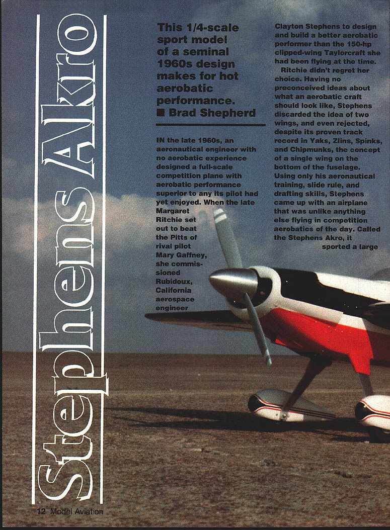
This 1/4-scale sport model of a seminal 1960s design makes for hot aerobatic performance. — Brad Shepherd
In the late 1960s, an aeronautical engineer with no aerobatic experience designed a full-scale competition plane with aerobatic performance superior to any his pilot had yet enjoyed. When the late Margaret Ritchie set out to beat the Pitts of rival pilot Mary Gaffney, she commissioned Rubidoux, California, aerospace engineer Clayton Stephens to design and build a better aerobatic performer than the 150-hp clipped-wing Taylorcraft she had been flying. Ritchie didn't regret her choice.
Having no preconceived ideas about what an aerobatic craft should look like, Stephens discarded the idea of two wings and even rejected, despite its proven track record in Yaks, Zlins, Spinks, and Chipmunks, the concept of a low wing. Using only his aeronautical training, slide rule, and drafting skills, Stephens came up with an airplane unlike anything else flying in competition aerobatics of the day. Called the Stephens Akro, it sported a large bubble canopy on top of a slender fuselage with relatively narrow landing gear.
If Stephens's design was radically original, his construction methods were not. Like many homebuilders, he used welded chrome-molybdenum steel tube fuselage members and fabric-covered tail surfaces. One key to the airplane's performance was the plywood-covered wing with a single, beefy spar that crossed the middle of the fuselage directly in front of the pilot's knees. By having the wing attached directly through the thrust line, the Akro could perform outside (negative-G) maneuvers with the same control forces and movements as upright (positive-G) maneuvers.
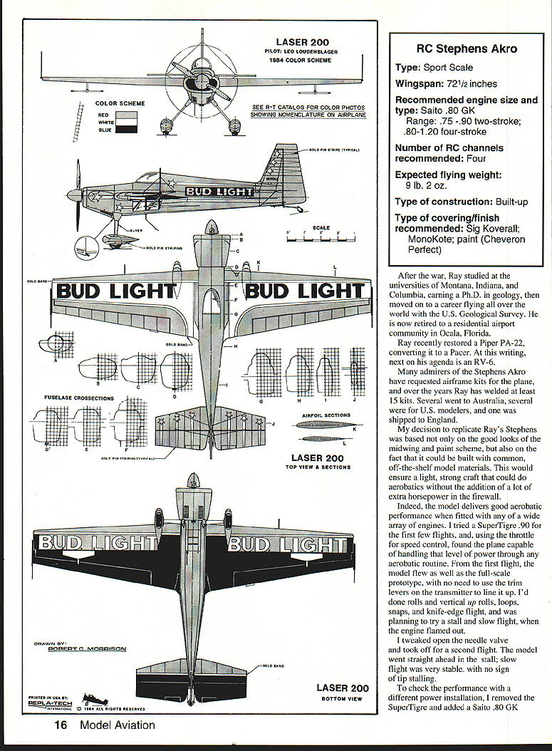
The Stephens Akro prompted a host of spin-offs, including two world champions and several national-title winners. The individual most responsible for elevating the design to world-class status was pilot Leo Loudenslager. Through a long series of modifications from 1971 through 1975, Loudenslager transformed a stock Akro (N10LL) into an entirely different airplane, later renamed the Laser 200 by a Canadian air-show promoter. Loudenslager's airplane beat all 20 Pitts Specials in the 1975 championships to win the first of a string of national Unlimited titles. In 1980, under the title Laser 200, the plane became World Aerobatic Champion.
Other competition aircraft that trace their ancestry to the Stephens include the Haigh Super Star, Diabolo, Extras, Wiggins Z, Rebel 200 and Rebel 300, the French TR, and the Australian Laser Aerobatics Model Z.
Nowadays many versions of the Stephens Akro can be seen flying in air shows and as sport aerobatic aircraft. Each is a little different, reflecting the personal touch of its owner/builder.
Ray Parker Variant
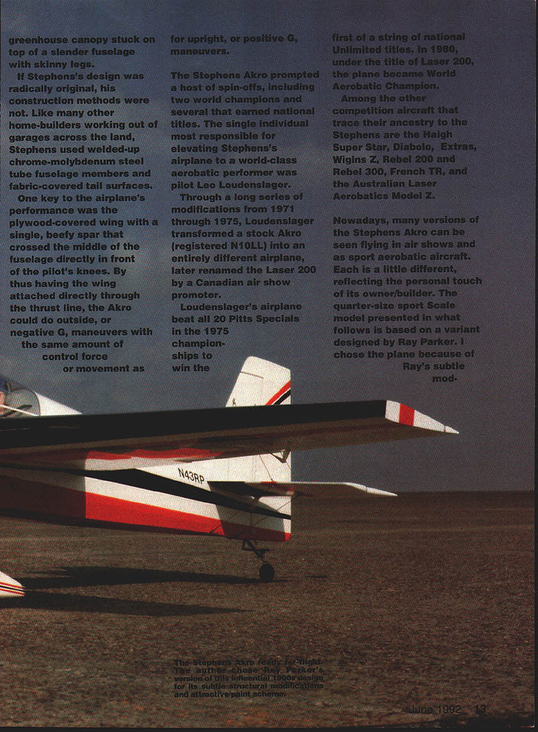
The quarter-size sport-scale model presented here is based on a variant designed by Ray Parker. I chose Ray's version because of his subtle modifications and attractive paint scheme.
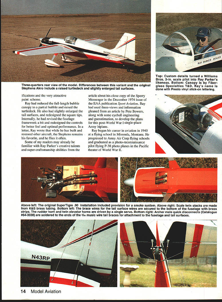
Ray reduced the full-length bubble canopy to a partial bubble, raised the turtledeck, slightly enlarged the tail surfaces, and redesigned the square tips. Internally he revised the fuselage framework and somewhat redesigned the controls for better feel and optimal performance. Ray has built and restored other aircraft; the Stephens remains his favorite and he flies it often.
Ray began his aviation career in 1940, attending flying school in Missoula, Montana. He progressed through Army Air Corps schools and graduated as a photo-reconnaissance pilot, flying P-38 photo planes in the Pacific theater of World War II. After the war Ray studied at the universities of Montana, Indiana, and Columbia, earning a Ph.D. in geology, and moved on to a career flying all over the world with the U.S. Geological Survey. Now retired, he lives in the residential airport community of Ocala, Florida. Ray recently restored a Piper PA-22 (converting it to a Pacer) and is planning an RV-6 as his next project.
Admirers of Ray's Stephens Akro have requested airframe kits over the years. Ray has welded at least 15 kits; several went to Australia and a few were shipped to England.
Flight Performance
The decision to replicate Ray's Stephens was based on its good looks, midwing paint scheme, and the fact it could be built from common off-the-shelf model materials, ensuring a light, strong craft capable of aerobatics with plenty of extra horsepower at the firewall.
Indeed, the model delivers strong aerobatic performance when fitted with a wide array of engines. I first tried a SuperTigre .90. Using throttle for speed control, the plane handled full power through aerobatic routines without needing trim adjustments on the transmitter. I performed rolls, vertical up rolls, loops, snaps, and knife-edge flight. On the first attempt at stall/slow flight the engine flamed out; after tweaking the open-needle valve I flew a second flight. The model flew straight ahead in the stall—very stable, with no sign of tip stalling.
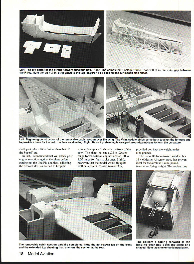
To check a different installation, I removed the SuperTigre and fitted a Saito .80 GK. The Hayes .60 mount remained in place; note the Saito's shaft protrudes a little farther than the SuperTigre's. Check your engine selection against the plans before cutting the Lite Ply doublers and adjust firewall slots as needed to keep the spinner backplate flush with the front of the cowl. The plans indicate a .75–.90 range for two-stroke engines and .80–1.20 for four-strokes. I believe the model would also fly well on a potent .65 two-stroke, provided the weight is kept under nine pounds.
The Saito .80 with a 14 x 6 Master Airscrew prop proved ideal for the airplane's nine-pound, two-ounce flying weight. The engine runs steady during all maneuvers, making aerobatics a pleasure. A smoke system is easily added and will increase enjoyment.
Specifications
- Type: Sport Scale
- Wingspan: 72-1/2 inches
- Recommended engine size/type: Saito .80 GK (recommended); range 75–90 two-stroke, 80–120 four-stroke
- Number of RC channels recommended: Four
- Expected flying weight: 9 lb 2 oz
- Type construction: Built-up
- Type covering/finish recommended: Sig Koverall, MonoKote, paint
- Color scheme: Red / Blue (RC)
(Full-size plans available. See plan sheet information.)
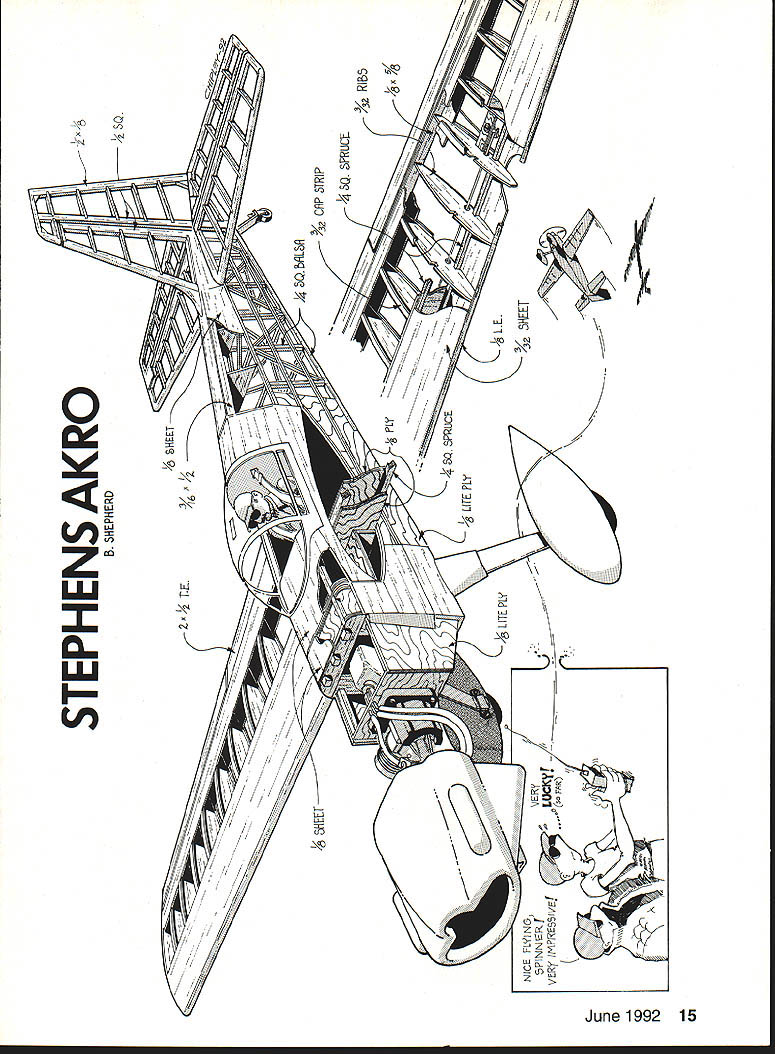
Construction
Take time to cut out a kit of parts before assembling major components. This gives a feel for the finished product, minimizes mistakes, and makes scratch-building easier. Trace parts outlines from the plan, then affix them to the wood using low-contact cement.
Wing
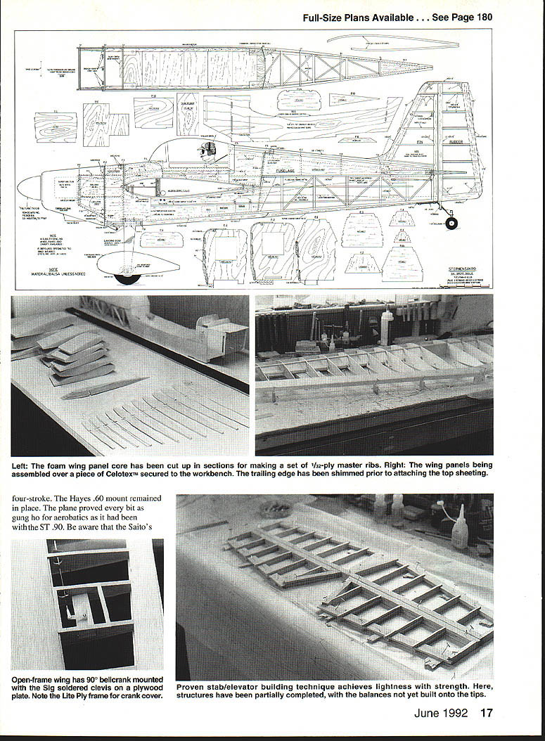
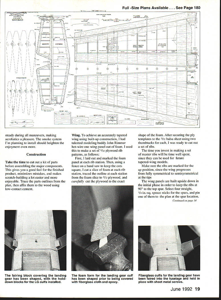
To achieve an accurately tapered wing with built-up construction, make a set of master ribs. One method is to hot-wire a foam wing panel and use it to create 1/32-in. plywood rib patterns.
- Lay out and mark the foam panel at each rib station.
- Using a fence on a bandsaw to keep cuts square, cut a foam slice at each rib station and trace each outline to 1/32-in. plywood. Cut the plywood ribs to match the foam templates.
- Secure the ply templates to 3/32-in. balsa sheet with thumbtacks and cut the balsa ribs. Master ribs are a good time investment because they can be reused for future tapered-wing models.
Make sure ribs are marked for the "up" position; the wing progresses from fully symmetrical at the root to semisymmetrical at the tips.
Build the wing panels upside down initially so the ribs are at 90° to the top spar. Select four straight 1/4-in. square spruce sticks for the spars and pin one to the plan at the spar location. Use waxed paper to protect the plan from glue spills. Pin a 1/4-in. square balsa stick along the "jig" line on the plan, trial-fit each rib on the top spar, trim as needed, and pin the ribs to the balsa jig behind the spar. Check each rib with a 90° triangle to ensure perpendicularity. Place the bottom spar in the rib cutouts and use thick CA (cyanoacrylate) on all joints.
If building the open-wing sport version, use cap strips: glue a 1/8 x 5/8-in. strip to the edge of the 3/32 x 1-1/2-in. balsa trailing edge sheet. For sport Scale competition (fully sheeted wing), glue the 1/8-in. strip to the edge of a 3-in.-wide balsa sheet.
To ensure a straight trailing edge, use a straightedge while gluing the strip to the sheet. Splice wood where necessary. Attach the trailing-edge sheet to the ribs with aliphatic glue, butt the 1/8 x 5/8-in. strip to the rear of the ribs, and pin in place. Position a straightedge along the front edge of the ribs and trim any overlong ribs until flush.
Slice two pieces of 1/8-in. balsa to 3/4 x 3/8 x 36 in. for the leading-edge strip. Pin and glue this strip to the ribs with CA. Bevel it with a long sanding block to provide a good gluing surface for the leading-edge sheeting.
Position 3-in.-wide, 3/32-in. leading-edge sheeting, mark where it meets the rear of the spar, and trim the wedge from the sheet. Use aliphatic glue on each rib where it contacts the sheeting, run a bead of glue along the top of the ribs, and pin the sheeting working from root to tip. Use pins only in the rib webs so they will be hidden when the top sheeting is later applied.
When covering the upper wing, sand the panel lightly, remove pins, and glue the top sheeting in place with aliphatic glue applied to the ribs. Pin until dry. Sand leading-edge sheeting to shape and glue cap strips on if doing the open-wing version. Install the wingbolt plate using 1/8-in. plywood and epoxy it per the plan.
Assemble the center section and gear mounts over the plan using the same methods as for the panels. When fitting the center to the fuselage, align carefully and epoxy the parts together. Fit the tank and controls per the plan.
After bottom sheeting the center section, finish sand the 1/8-in. trailing edge flush with the 3/32-in. sheeting. Cut trailing-edge pieces to proper angles for the center section and aileron positions, trial-fit, and glue seams with CA. Mark and cut the ailerons, sand a bevel into the leading edge, and set them aside. Decide whether to use scale or sport wingtips and build the tips accordingly.
Tail Surfaces
The tail construction technique used here is simple and produces a strong, straight empennage. All necessary details are on the plans; refer to the section drawings if questions arise.
Glue the verticals in place, add top cap strips, and install the top center section sheet aft of the spars. Epoxy ribs 1-A flush with the bottoms of the number-one ribs. Glue 1/8 x 3/8-in. plywood pieces to the leading edge so tops are flush with the top of ribs 1-A. Epoxy WBP (exterior-grade plywood) to the 1-A ribs and to the ply pieces at the leading edge; epoxy the rear WBP to the top sheet.
Fuselage
- Glue the 1/8-in. balsa sides to the Lite Ply doublers with contact cement and seal edges with CA.
- Build the right side directly over the plan, then build the second side atop the first over waxed paper. If the Lite Ply is less than a full 1/8 in. thick, shim the forward area so the 1/4-in. built-up rear portion on the left side is flush with the 1/8-in. sheet fuselage side.
- Remove and separate the sides. Pin down the top-view plan from the F-6 former to the tail post using the inside lines on the plan as a guide. Install formers in their slots and glue in place; use pins and rubber-band persuaders to pull the sides in across the top where needed.
- Secure the engine mount to the firewall and effectively seal the front end from fuel entrainment. After inserting bolts through the firewall, solder wire across the bolt heads, epoxy the wire liberally, and epoxy the firewall into the Lite Ply slots with a quick-curing epoxy such as Sig Kwik Set. Pull the sides in by hand until the epoxy sets.
- Cut and glue 1/4-in. square balsa rear fuselage crosspieces; note the top pieces are slightly longer than the bottom ones. Glue diagonal braces. Install LGPF with epoxy and sheet the bottom inside the lite-ply doublers. Glue 1/8-in. sheet F-10 in place. Remove the fuselage from the plan and position and glue F-9.
- Install 3/16 x 1/2-in. top rear turtledeck stringers between formers F-6 and F-9. Fit and glue formers F-7 and F-8. Glue 1/8-in. medium-weight balsa sheet to the turtledeck sides, sand flush with the 3/16-in. top stringers, then glue the bottom cap to the top 1/4-in. turtledeck sheet. Pin scrap balsa on top of the longerons at the stabilizer position and glue the top cap F-10 to the 1/8-in. square tail post and F-9.
- Finish sheeting the turtledeck over the stabilizer and remove scrap balsa. Glue 1/4-in. spruce braces between formers F-2 and F-3.
- Shape corner-covering A-grain 1/8-in. balsa sheets by wrapping around paint cans and securing with rubber bands until dry.
- Cut maple wing hold-down blocks for each corner of the fuselage opening, install with epoxy, seat the wing in the saddle, true it to the fuselage centerline, and pin it. Drill and fit 3/16-in. dowels through the wing ply hold-down plates and maple blocks as temporary locating dowels. Tap the maple blocks for 1/4-20 bolts and check with nylon bolts. Drill holes in the wing plates to 1/4 in., position the wing on the fuselage, and bolt it down. Protect the wing center section and formers with waxed paper or plastic wrap, then position formers F-3A and F-6A and clamp.
- Place the 1/8-in. saddle strip over the sheeting, pin and glue it to F-3A and F-6A. Position formers F-4 and F-5, glue 1/8 x 1/4-in. strips between them, and begin sheeting the cabin section. Wrap balsa sheeting around paint cans as shown on the plans to form curvature. Continue sheeting until the cabin is complete, including the hold-down tab on the front and the dowel-and-bolt at the rear. Sheet area between F-2 and F-3, remove the cabin section, and unbolt the wing.
- Install throttle pushrod tubes and make provisions for an optional smoke system. Assemble and install the fuel tank and optional smoke system tank. Install the bottom double 1/4-in. sheet between F-2 and F-3, former FB, and bottom stringers.
- Position landing gear and drill mounting holes. Shape balsa forward of the landing gear to blend with the cowl and former FB per the plans. Bolt the engine and spinner to the firewall, position the cowl using a straightedge, trim if necessary, epoxy hardwood cowl hold-down blocks to F-2, replace the cowl, and drill screw holes through the cowl and blocks.
- Pack foam around fuel and smoke tanks and glue 1/4-in. square spruce crosspieces between F-2 and F-3. Epoxy F-1T and F-1B in place. Fuel-proof the entire front end forward of F-2 with a coating of epoxy.
Build the landing-gear fairing from 1/4-in. balsa, sand flush with FB and the forward block, install a 1/4-in. dowel in the center, drill through the dowel and landing gear, and tap the gear for a 4-40 bolt to secure the fairing. To make landing-gear cuffs, sand foam to shape, mount on Lite Ply scrap, cover with fiberglass and epoxy, then remove the foam, leaving a hollow fiberglass shell. Give cuffs another coat of epoxy inside and out, glue hardwood blocks to landing-gear fairing blocks, and attach cuffs with sheet-metal screws.
Covering and Finishing
- Give the fuselage and tail surfaces two coats of Sig nitrate dope, sanding off the fuzz between coats. Cover structures with Sig Koverall, attaching the Koverall dry and brushing nitrate through the material wherever it contacts nitrate-doped wood.
- After installing and gluing the fin, tighten the covering using an iron set on medium heat. Take care not to overheat Koverall; excess heat can distort the underlying structure.
- Apply five coats of nitrate dope to the fuselage and tail surfaces, then paint with Chevron Perfect paint in colors to match the Super MonoKote used on the wings.
- Add scale details: a Williams Bros. three-inch pilot figure was customized into a likeness of Ray Parker with a fabric cap, plywood visor, balsa headphones, and shoulder straps from a Futaba neck strap. Paint the instrument panel flat black, cut out Gorham Model Products instruments, and glue them on.
Fiberglass cowl and wheel pants, and the pulled canopy, are available from Fiberglass Specialties T&D (Steve Durecki). Tru-Turn nose art was created by Bob Obenberger of Romco and adds an almost exactly scale finishing touch.
Notes and Recommendations
- Check spinner backplate fit and engine shaft length before cutting Lite Ply doublers; adjust firewall slots so the spinner backplate is flush with the front of the cowl.
- The plans indicate a two-stroke engine range of .75–.90 and a four-stroke range of .80–1.20; however, the model should fly well on a potent .65 two-stroke if kept light.
- The Saito .80 with a 14 x 6 prop works well for a 9 lb 2 oz flying weight.
- A smoke system is straightforward to install and enhances airshow performance.
Contact and Credits
If you live near Ocala, Florida, consider visiting Ray Parker at Leeward Air Ranch. Ray is the craftsman behind this variant of the Stephens Akro.
Acknowledgements: Bud Davisson, Emily Zimmerman, and Ray Parker contributed information for this article. Special thanks to Steve Durecki (Fiberglass Specialties T&D) and Bob Obenberger (Romco) for cowl, wheel pants, canopy, and nose-art support.
Transcribed from original scans by AI. Minor OCR errors may remain.

