
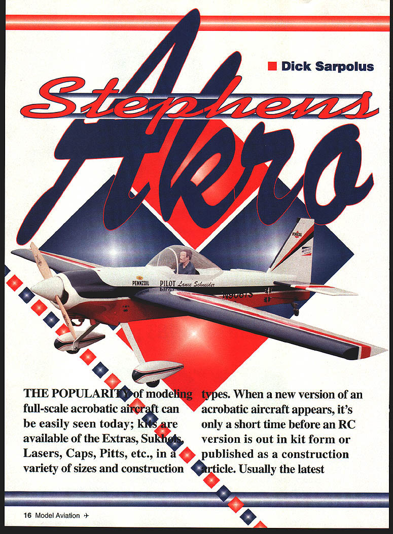
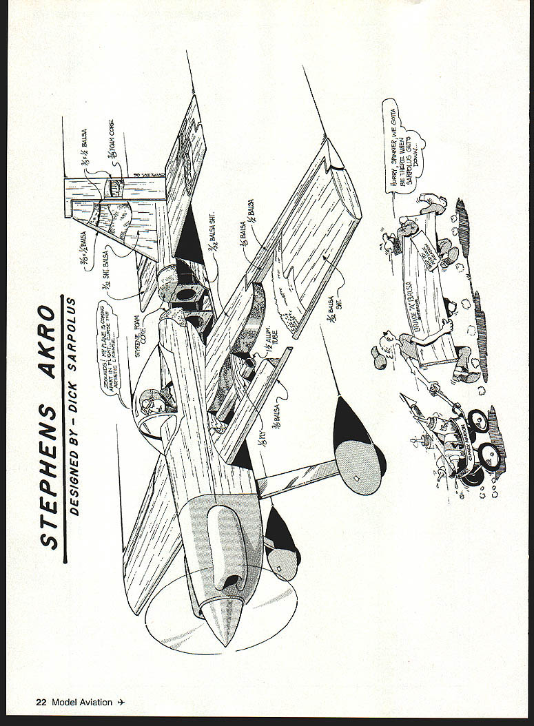
Stephens Akro
Dick Sarpolus
The popularity of modeling full-scale acrobatic aircraft is obvious today; kits are available of Extras, Sukhois, Lasers, Caps, Pitts, etc., in a variety of sizes and construction types. When a new acrobatic design appears, an RC version soon follows. Usually the latest designs get the most attention at the flying fields.
I like the newer aircraft, but one older design I've always admired has never had much impact in the modeling world: the Stephens Akro.
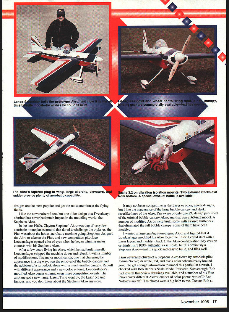
In the late 1960s Clayton Stephens' Akro was one of the few acrobatic monoplanes that dared to challenge the biplanes (the Pitts being the hottest acrobatic machine). Stephens designed the Akro to take on the Pitts, and pilot Leo Loudenslager opened a lot of eyes when he began winning major contests with his Stephens Akro. After a few years Loudenslager rebuilt his Akro with many modifications — notably replacing the full bubble canopy with a turtledeck and smaller canopy — and the airplane evolved into the Laser. The Laser became famous, and the original Stephens Akro faded from view.
I prefer the original Akro's large bubble canopy and sleek racer-like lines. I was aware of only one RC design published of the original bubble-canopy Akro (a .60-size model). Wanting a large gas/ignition-engine Akro, I started from a Laser layout and modified it back toward the Akro configuration. My version isn't 100% scale, but it's obviously a Stephens Akro — quick and easy to build, and it flies well.
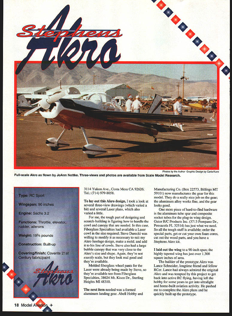
I used photos of JoAnn Nottke's Stephens Akro for color and detail references; Bob Banka's Scale Model Research had several three-view drawings and Foto Paaks covering different Akros, including JoAnn Nottke's aircraft. The photos were a big help.
Contact:
- Scale Model Research, 3114 Yukon Ave., Costa Mesa, CA 92626; Tel: (714) 979-8058.
Specifications
- Type: RC Sport
- Wingspan: 90 in
- Engine: Air Hobbies Sachs 3.2
- Functions: throttle, elevator, rudder, ailerons
- Weight: approx. 19¼ lb (prototype)
- Construction: built-up (foam-core wing and tail, balsa/ply fuselage)
- Covering/finish: Coverite 21st Century fabric and paint
Suppliers / Special Parts
- Fiberglass Specialties — Laser cowl (modified), large bubble canopy, molded fiberglass wheel pants. Fiberglass Specialties, 38624 Mt. Kisco Dr., Sterling Heights, MI 48310.
- Abell Hobby Manufacturing Co. — formed aluminum landing gear for the model. P.O. Box 22573, Billings, MT 59101.
- Gator R/C Products, Inc. — aluminum tube spar and composite socket tubes for plug-in wing design. 3713 Pompano Dr., Pensacola, FL 32514.
- Scale references and photos from Scale Model Research (address above).
Construction
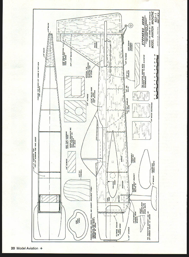
The construction is conventional and well proven. The fuselage is a box structure with balsa sides and plywood doublers. Foam-cored top blocks are sheeted with balsa, as are the foam-cored tail surfaces. The wing panels are foam-cored with plywood ribs to retain the composite socket tubes for the aluminum tube spar.
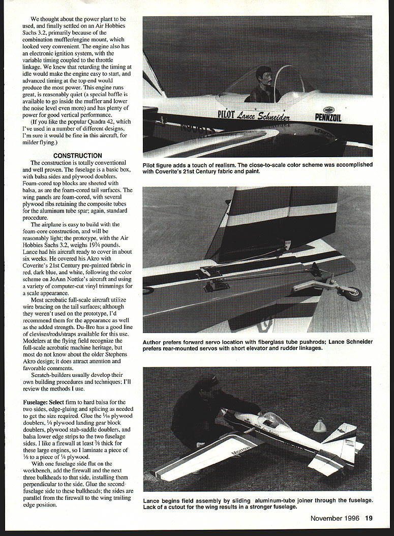
The prototype (with the Air Hobbies Sachs 3.2) weighed about 19¼ lb. Lance Schneider built the prototype and had it ready for covering in about six weeks, using Coverite 21st Century pre-painted fabric in red, dark blue, and white with computer-cut vinyl trim for scale appearance.
Most full-scale acrobatic aircraft use wire bracing on the tail surfaces; although not used on the prototype, I recommend them for appearance and added strength. Du-Bro makes good clevises, rods, and straps for this use.
Scratch-builders develop their own procedures; below are the methods I used.
Fuselage
- Select firm to hard balsa for both fuselage sides; edge-glue and splice as needed.
- Glue 1/16" plywood doublers, 1/4" plywood landing-gear block doublers, plywood stab-saddle doublers, and balsa lower edge strips to the fuselage sides.
- Firewall: laminate 3/8" to 1/4" plywood (I prefer at least 3/8" plywood for large engines). Add triangle stock and heavy fiberglass cloth behind the firewall to reinforce its joint with the sides. Install several small screws through the fuselage sides into the firewall for extra reinforcement.
- With one side flat on the bench, install the firewall and next three bulkheads perpendicular to that side, then glue the second side to these bulkheads. Ensure sides are parallel from the firewall to the wing trailing-edge position.
- Install rear bulkheads and pull the tail end together, making sure the fuselage tapers straight for the foam rear top block to fit correctly. Trial-fit the foam rear top block and adjust bulkheads as needed.
- Sheet the foam fuselage top blocks with balsa (three blocks are used because of taper). Cut the cockpit opening in the top blocks before gluing them in place. Use contact cement (I recommend Dave Brown's Southern Sorghum), thin epoxy, or other preferred adhesive.
- Fit the 1/2" I.D. phenolic tube through the fuselage sides to accept the aluminum spar but do not glue it yet. After wing panels are fitted and alignment checked, epoxy the tube in place.
- Cut the slot through the rear top block for the vertical fin before gluing the block in place.
- Epoxy the plywood landing-gear mount into the fuselage. Add hardwood blocks where the holes will be drilled and tapped for the nylon gear retaining bolts. Use an aluminum right-angle bracket on each side of the gear mount and bolt it through the fuselage sides to help prevent the gear from pulling out in a rough landing.
- After engine mount arrangement and drilling firewall holes for fuel tubing and throttle linkage, glue the plywood forward bottom piece to the fuselage. Before sheeting the bottom, cut holes in the rear bulkheads and fit elevator and rudder pushrods.
- Provide a removable Lite Ply hatch on the fuselage bottom for access to radio gear and fuel tank; retain it with screws.
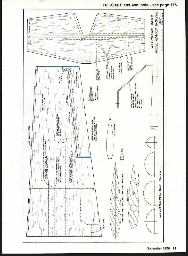
Wing
Work on foam wing cores before sheeting:
- Fit a 1/8" plywood rib at the root; cut the core 12" out from the root for a second 1/8" plywood rib. The hole in the second rib for the spar tube establishes dihedral — ensure the aluminum spar will be parallel to the top wing surface (dihedral is in the bottom surface).
- Remove foam for the spar tube by first making a pilot hole with a heated metal rod and then using a cutting wire or a large round file. Epoxy the spar tube into the foam core through the plywood ribs.
- Create a tunnel from the root to the aileron servo location for the servo extension cable — melt a tunnel through the foam using the heated metal rod technique.
- Glue a 3/8" dowel locating pin into the wing panel through the root plywood rib and a short plywood rib farther out.
- Sheet the cores with 3/32" medium balsa, edge-glued as necessary. For tight edge joints, use a taped joint technique: tape joints, flip and glue edges over the bench, scrape excess glue, weight until dry, peel tape off and use taped side as the outer surface.
- Trim and block-sand the leading edge square. Add an oversized leading-edge strip and plane/sand to shape. Add wingtip sheeting and round the edges slightly.
- Cut the ailerons from the sheeted wing, trim to allow balsa edging, glue edging in place and sand to shape. Hinge the ailerons along the centerline using sturdy, freely moving hinges. Simulated aileron counterbalance at the tip is optional for scale detail.
- Cut recesses in the lower wing for aileron servo mounting; epoxy plywood mounting pieces so they protrude enough to hook up the aileron pushrods.
- For reinforcement, apply fiberglass cloth and epoxy around the inboard wing ends, extending about eight inches from the panel roots.
- With the phenolic tube in the fuselage (not yet glued), slide the aluminum tube spar in place and add both wing panels. Check that dihedral is equal on both sides and that wing panels fit closely to the fuselage. Add a layer of balsa to the wing root surface if needed for a better fit, and shim or elongate holes in the fuselage sides as required.
- When panels are aligned, epoxy the phenolic tube into the fuselage working through the open halves, ensuring both panels have zero angle of incidence. The 3/8" dowel stub in the wing roots establishes alignment — move or shim holes as needed.
- Retain wing panels on the spar with a hardwood block glued into the wing, flush with the wing surface, and drill/tap for a 10-32 steel retaining bolt that extends into the aluminum tube spar. Drill the second wing panel after the first is secured for easy alignment. Leave the tube spar in one wing when disassembling for easier alignment.
- The bottom hatch provides access for hooking up aileron cables when wing panels are mounted.
Wing component notes (from plan detail):
- 1/8" leading edge
- 1/8" trailing edge
- Sheet covering (3/32" balsa)
- 1/8" plywood ribs and root rib details
- 1/4" plywood spar and root rib
- Plywood block for wing tip
- Drain hole and hinge line locations as per plan
Tail Surfaces
- Build tail surfaces flat on the bench. Cut 3/8" hot-wire foam sheets to shape, add 3/8" x 1/2" balsa edging and reinforcing, then sheet with 3/32" balsa like the wing cores.
- Simulated counterbalance areas on the elevators and rudder are optional but add scale appearance.
- With the wing mounted, add and align the horizontal stab with the wing. Add 1/4" balsa between fuselage sides to provide extra gluing area for the stab and consider a narrow strip of fiberglass cloth and epoxy on the outside of the joint.
- Add the vertical fin aligned perpendicular to the stab. A plywood section on the bottom rear of the fuselage mounts the leaf-spring tail wheel assembly.
- Use 1/4" plywood for control horn mounts, recessing and epoxying them into the tail surfaces. Mount horns with self-tapping screws.
- Use appropriate hinges—molded nylon flat hinges or hinge-point style—cutting slots or drilling holes to permit a close hinge-line gap and full movement.
Controls, Radio and Linkages
- Use 4-40 threaded rods and clevises for linkages; fiberglass tube pushrods for elevator linkages.
- Use separate servos for each elevator so pushrods can be straight from servo arm to control horn. If pushrods cross in the fuselage, mount one elevator servo slightly higher to avoid rubbing. If mounting servos protruding from the fuselage sides (as on the prototype), reinforce around servo openings with thin plywood.
- Tail wheel steering is tied to the rudder with small springs; linkage can be a pushrod or twin cable pull-pull.
- Install a long Y harness for the two aileron servos in the wing panels.
- Use a 1,200 mAh battery pack wrapped in foam rubber and position it beneath the fuel tank. Relocate the battery for proper balance as needed (behind the wing if required).
Engine, Cowl and Landing Gear
- Engine used on prototype: Air Hobbies Sachs 3.2 (selected for convenient combination muffler/engine mount and electronic ignition with variable timing tied to the throttle). Retarding timing at idle aids starting; advanced timing at the top end produces power. The engine runs well, is reasonably quiet (special baffle available for the muffler), and provides plenty of vertical performance.
- Alternative: popular Quadra 42 should be fine for milder flying.
- Fiberglass cowl: trim to clear the engine cylinder, exhaust and carburetor. Mount cowl with several 10-32 nylon bolts into the fuselage.
- Spinner: 3-1/2" spinner used on the prototype (CB unit).
- Ignition and radio switches: mount ignition switch on fuselage side close to the nose; mount radio system switch on fuselage side away from ignition.
- Wheel pants: fiberglass wheel pants mounted to axles on the aluminum gear with brackets.
- Landing gear: formed-aluminum gear from Abell Hobby; reinforce gear mount with plywood and aluminum brackets as described earlier.
Covering and Finish
- Cover with Coverite 21st Century pre-painted iron-on fabric. Paint fiberglass cowl, wheel pants, and aluminum landing gear using matching 21st Century spray paint. Add vinyl stick-on lettering and decals for realistic appearance and add a pilot figure for scale realism.
- The prototype weighed a bit under 20 lb after covering and finishing.
Flying
- Test flights were conducted on a windy day. The Sachs 3.2 provided strong takeoff performance.
- The model is easy to fly for mild sport flying and capable in aerobatics. It performs well in low-elevation figures, knife-edge, limited vertical maneuvers, tall slides, humpty-bumps, snaps, and more (pilot skill required).
- The combination of large control surfaces, reasonably light weight and sufficient power makes the Akro a satisfying sport and acrobatic model.
Notes and Recommendations
- Consider adding wire bracing to tail surfaces for strength and scale appearance.
- Reinforce around servo openings and gear mount areas with plywood or hardwood blocks.
- Use fiberglass cloth and epoxy for additional reinforcement around wing roots and other high-load areas.
- If using a plug-in wing, ensure careful alignment and secure retaining bolts into hardwood blocks.
Consider the Stephens Akro for an easy-building, scale-looking sport machine that also has full acrobatic capability.
— Dick Sarpolus 32 Alameda Ct. Shrewsbury, NJ 07702
Transcribed from original scans by AI. Minor OCR errors may remain.

