
Stitchin
L. F. Randolph
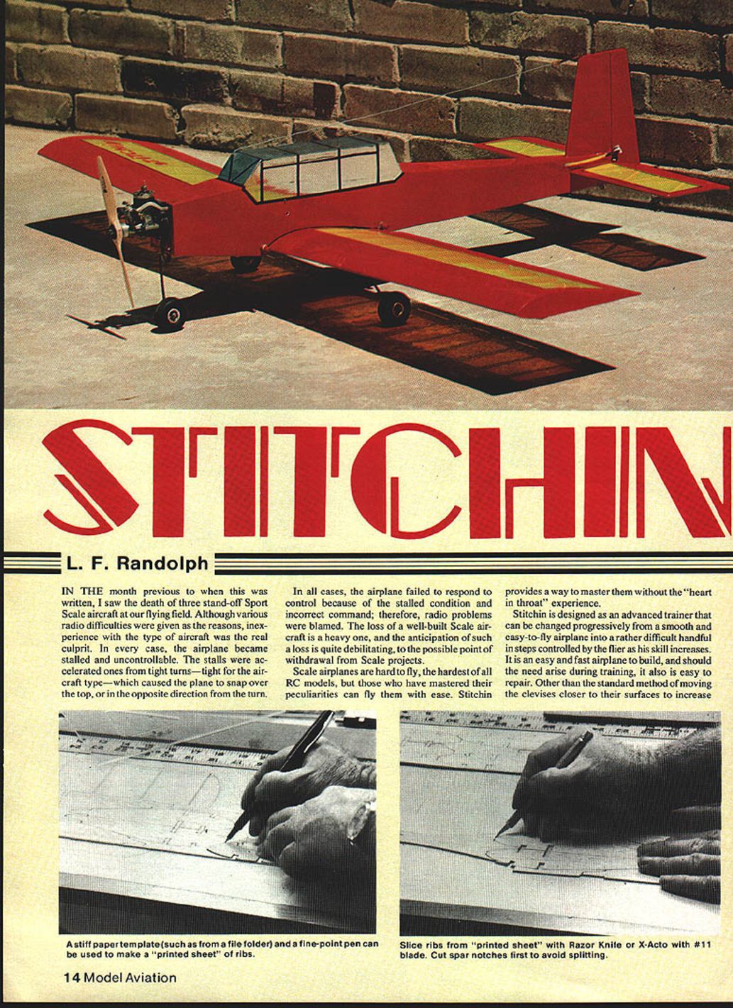
In the month previous to when this was written, I saw the death of three stand-off Sport Scale aircraft at our flying field. Although various radio difficulties were given as the reasons, inexperience with the type of aircraft was the real culprit. In every case the airplane became stalled and uncontrollable. The stalls were accelerated ones from tight turns—tight for the aircraft type—which caused the plane to snap over the top, or in the opposite direction from the turn.
In all cases the airplane failed to respond to control because of the stalled condition and incorrect command; therefore radio problems were blamed. The loss of a well-built Scale aircraft is a heavy one, and the anticipation of such a loss is quite debilitating, to the possible point of withdrawal from Scale projects.
Scale airplanes are hard to fly, the hardest of all RC models, but those who have mastered their peculiarities can fly them with ease. Stitchin provides a way to master them without the "heart-in-throat" experience.
Design and purpose
Stitchin is designed as an advanced trainer that can be changed progressively from a smooth and easy-to-fly airplane into a rather difficult handful in steps controlled by the flier as his skill increases. It is an easy and fast airplane to build, and should the need arise during training, it also is easy to repair.
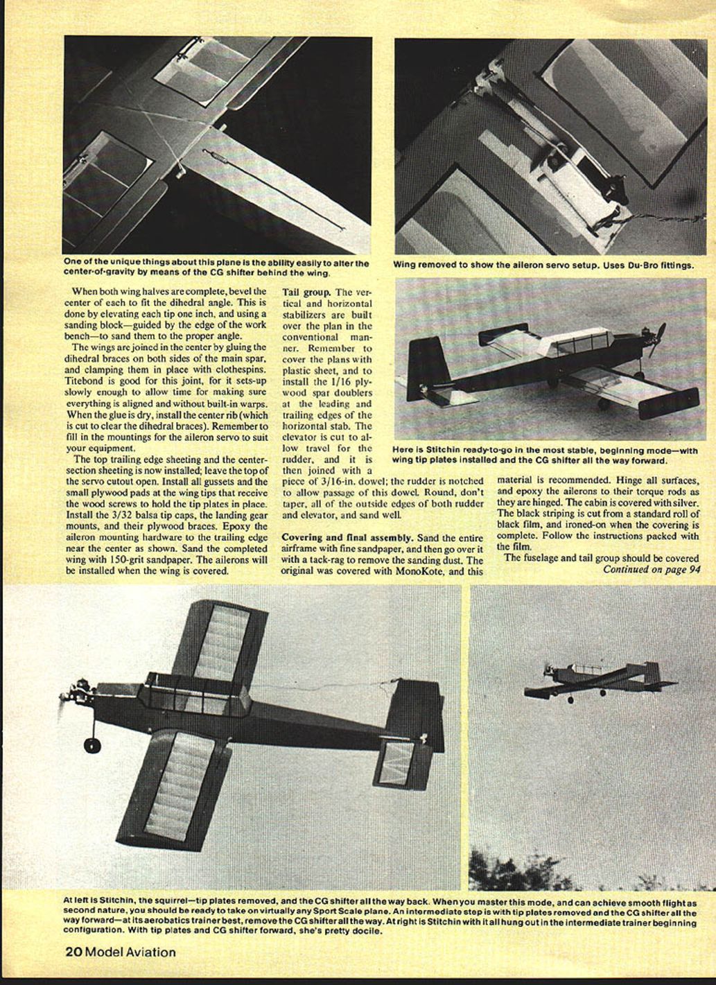
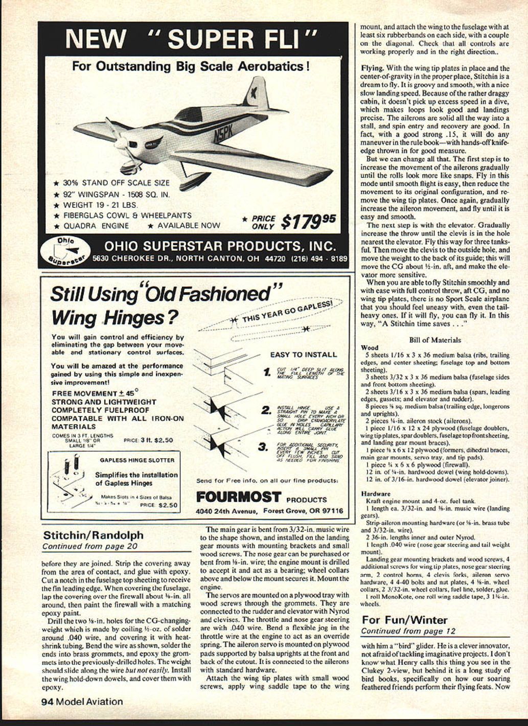
Other than the standard method of moving the clevises closer to their surfaces to increase control movement, there are two additional changes that will alter its performance markedly: the removal of the wing tip plates, and changing the center-of-gravity (CG) to a more aft location.
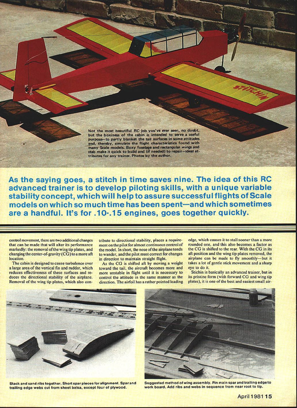
The cabin is designed to cause turbulence over a large area of the vertical fin and rudder, which reduces effectiveness of these surfaces and reduces the directional stability of the airplane. Removal of the wing tip plates, which also contribute to directional stability, places a requirement on the pilot for almost continuous control of the model. In short, the nose of the airplane tends to wander, and the pilot must correct for changes in direction to maintain straight flight.
As the CG is shifted aft by moving a weight toward the tail, the aircraft becomes more and more unstable in flight until it is necessary to control the attitude in the same manner as the direction. The airfoil has a rather pointed leading edge, which causes it to stall sooner than a more rounded one, and this also becomes a factor as the CG is shifted to the rear. With the CG in its aft position and the wing tip plates removed, the airplane can be made to fly smoothly—but it takes a lot of gentle stick movement and a sharp eye to do it.
Stitchin is basically an advanced trainer, but in its pristine form (with forward CG and wing tip plates), it is one of the best and easiest small airplanes I have ever flown. The tricycle landing gear is there for easy ground handling, although the Scale purist might rather have a conventional tail-dragger. I have never enjoyed kicking an airplane down a runway, model or otherwise, so it is a tricycle gear for me.
Construction overview
To build this airplane, I suggest you start by assembling a kit. Any scratch-built project goes easier if the parts are gathered together before construction is begun. The spars can be purchased from your dealer or stripped from sheets of the proper thickness.
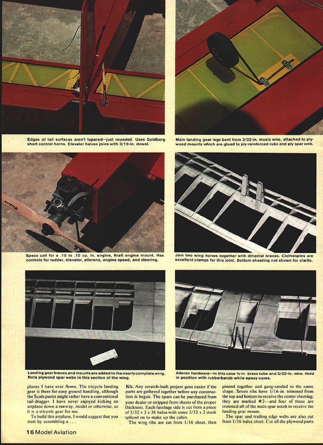
Each fuselage side is cut from a piece of 3/32 x 3 x 36 balsa with some 3/32 x 2 stock spliced on to make up the cabin. The wing ribs are cut from 1/16 sheet, then pinned together and gang-sanded to the same shape. Seven ribs have 1/16-in. trimmed from the top and bottom to receive the center sheeting; they are marked #2. Four of these are trimmed aft of the main spar notch to receive the landing gear mount.
The spar and trailing-edge webs are cut from 1/16 balsa sheet. Cut all the plywood parts from the specified thickness of wood. Stack the ribs together and gang-sand them to the same shape. Use short spar pieces for alignment and to maintain spacing.
Pin the main spar and trailing edge to the workboard. Add ribs and webs in sequence from root to tip. Sheet the center section and install the plywood spar webs and the 1/4-in. dowel wing mount and plywood reinforcements for the landing gear mount as shown on the plans. Apply the bottom sheeting next.
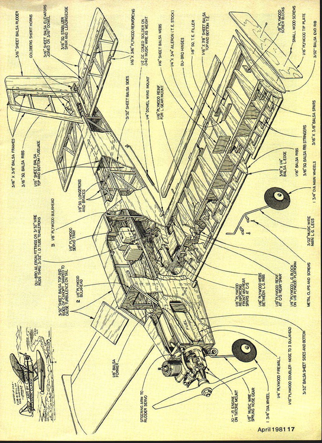
Install aileron hardware and hinges during final wing finishing. The tail surfaces aren’t tapered—just rounded. The elevator halves join on a 3/16-in. dowel. Use short control horns for elevator and rudder.
Main landing gear legs are bent from 3/32-in. music wire and attached to plywood mounts glued to ply-reinforced fuselage blocks. Install the steering arm to the rudder servo and check all controls (rudder, elevator, ailerons) for correct operation before final covering.
Fuselage
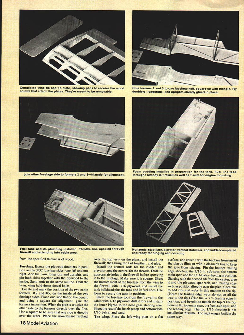
Epoxy the plywood doublers in position on the 3/32 fuselage sides, one left and one right. Add the 1/8-in. longerons and uprights, and pin both sides together with the plywood to the inside. Sand both to the same outline. Drill the 1/8-in. wing hold-down dowel holes.
Locate and mark the position of the two cabin formers, #2 and #5, on the inside of the two fuselage sides. Place one side flat on the bench and, using a square for alignment, glue the formers in position. When the glue is set, glue the other side to the formers directly over the first. Use a square to be sure that one side is directly over the other. Place the now-square fuselage over the top view on the plans, and install the firewall; then bring the tail together and glue.
Install the control rods for the rudder and elevator, and the control for the throttle. Drill the appropriate holes in the firewall before epoxying it to the fuselage. Make sure it is square. Sheet the bottom front of the fuselage from the wing to the firewall with 1/16 plywood, and install the tank bulkhead plus the tank and its fuel lines. Use foam to secure the tank in position.
Sheet the fuselage top from the firewall to the cabin with 1/16 plywood; drill it for and install the inner Nyrod to the nose gear steering arm. Sheet the rest of the fuselage top and bottom with 1/16 balsa, and sand.
The wing
Place the left wing plan on a flat surface and cover it with the backing from one of the plastic films or with a cleaner's bag to keep the glue from sticking. Pin the bottom trailing edge sheeting, the 3/16-in. sub-spar, the bottom main spar, and the 1/16 balsa sheeting in position. Starting with the second rib from the center, glue in the plywood spar web and trailing-edge web directly over the plan. Continue to add ribs and webs in this manner to the tip. (Note: the trailing-edge webs do not go all the way to the tip.)
Glue the 1/16 x 1/4 trailing edge in position, and bevel it to match the top of the rib. Glue in the top main spar, the front sub-spar, and the leading edge. The top 1/16 sheeting is not installed at this time. The right wing is built in the same way.
When both wing halves are complete, bevel the center of each to fit the dihedral angle. This is done by elevating each tip one inch and using a sanding block—guided by the edge of the workbench—to sand them to the proper angle.
The wings are joined in the center by gluing the dihedral braces on both sides of the main spar, and clamping them in place with clothespins. Titebond is good for this joint, since it sets up slowly enough to allow time for making sure everything is aligned and without built-in warps. When the glue is dry, install the center rib (which is cut to clear the dihedral braces). Remember to fill in the mountings for the aileron servo to suit your equipment.
The top trailing-edge sheeting and the center-section sheeting are now installed; leave the top of the servo cutout open. Install all gussets and the small plywood pads at the wing tips that receive the wood screws to hold the tip plates in place. Install the 3/32 balsa tip caps, the landing gear mounts, and their plywood braces. Epoxy the aileron mounting hardware to the trailing edge near the center as shown. Sand the completed wing with 150-grit sandpaper. The ailerons will be installed when the wing is covered.
Note: Tail-surface edges are rounded only—not tapered.
Tail group
The vertical and horizontal stabilizers are built over the plan in the conventional manner. Remember to cover the plans with plastic sheet, and to install the 1/16 plywood spar doublers at the leading and trailing edges of the horizontal stab. The elevator is cut to allow low travel for the rudder, and it is then joined with a piece of 3/16-in. dowel; the rudder is notched to allow passage of this dowel. Round, don't taper, all of the outside edges of both rudder and elevator, and sand well.
Covering and final assembly
Sand the entire airframe with fine sandpaper, and then go over it with a tack rag to remove the sanding dust. The original was covered with MonoKote, and this material is recommended. Hinge all surfaces, and epoxy the ailerons to their torque rods as they are hinged. The cabin is covered with silver. The black striping is cut from a standard roll of black film and ironed on when the covering is complete. Follow the instructions packed with the film.
The fuselage and tail group should be covered before they are joined. Strip the covering away from the area of contact, and glue with epoxy. Cut a notch in the fuselage top sheeting to receive the fin leading edge. When covering the fuselage, lap the covering over the firewall about 1/2 in. all around, then paint the firewall with a matching epoxy paint.
Drill the two 1/8-in. holes for the CG-changing weight, which is made by coiling 1/2 oz. of solder around .040 wire and covering it with heat-shrink tubing. Bend the wire as shown, solder the ends into brass grommets, and epoxy the grommets into the previously-drilled holes. The weight should slide along the wire but not easily. Install the wing hold-down dowels and cover them with epoxy.
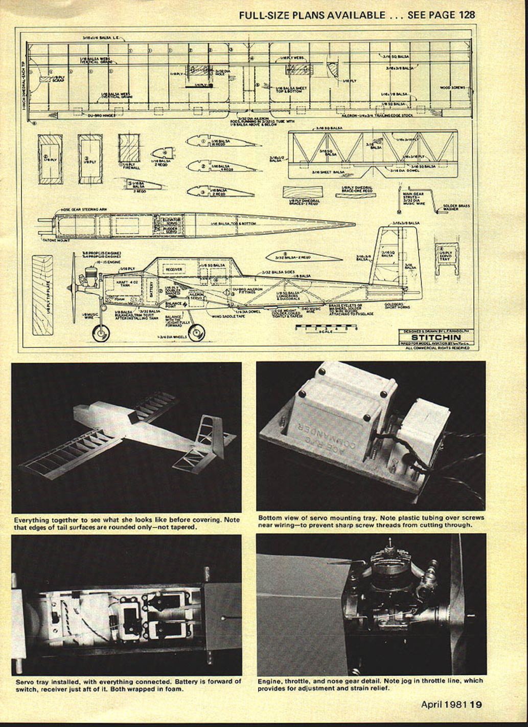
The main gear is bent from 3/32-in. music wire in the shape shown, and installed on the landing gear mounts with mounting brackets and small wood screws. The nose gear can be purchased or bent from 1/8-in. wire; the engine mount is drilled to accept it and act as a bearing; wheel collars above and below the mount secure it. Mount the engine.
The servos are mounted on a plywood tray with wood screws through the grommets. They are connected to the rudder and elevator with Nyrod and clevises. The throttle and nose gear steering use .040 wire. Bend a flexible jog in the throttle wire at the engine to act as an override spring. The aileron servo is mounted on plywood pads supported by balsa uprights at the front and back of the cutout. It is connected to the ailerons with standard hardware.
Attach the wing tip plates with small wood screws, apply wing saddle tape to the wing mount, and attach the wing to the fuselage with at least six rubber bands on each side, with a couple on the diagonal. Check that all controls are working properly and in the right direction.
Flying
With the wing tip plates in place and the center-of-gravity in the proper place, Stitchin is a dream to fly. It is groovy and smooth, with a nice slow landing speed. Because of the rather draggy cabin, it doesn't pick up excess speed in a dive, which makes loops look good and landings precise. The ailerons are solid all the way into a stall, and spin entry and recovery are good. In fact, with a good strong .15 it will do any maneuver in the rule book — with hands-off knife-edge thrown in for good measure.
But we can change all that.
The first step is to increase the movement of the ailerons gradually until the rolls look more like snaps. Fly in this mode until smooth flight is easy, then reduce the movement to its original configuration and remove the wing tip plates. Once again, gradually increase the aileron movement, and fly until it is easy and smooth.
The next step is with the elevator. Gradually increase the throw until the clevis is in the hole nearest the elevator. Fly this way for three tanksful. Then move the clevis to the outside hole and move the weight to the back of its guide; this will move the CG about 1/2 in. aft, and make the elevator more sensitive.
When you are able to fly Stitchin smoothly and with ease with full control throw, aft CG, and no wing tip plates, there is no Sport Scale airplane that you should feel uneasy with, even the tail-heavy ones. If it will fly, you can fly it. In this way, "A Stitchin time saves ..."
Bill of Materials
#### Wood
- 5 sheets 1/16 x 3 x 36 medium balsa (ribs, trailing edges, and center sheeting; fuselage top and bottom sheeting)
- 3 sheets 3/32 x 3 x 36 medium balsa (fuselage sides and front bottom sheeting)
- 2 sheets 3/16 x 3 x 36 medium balsa (spars, leading edges, gussets, and elevator and rudder)
- 8 pieces 1/8-in. medium balsa (trailing edge, longerons and uprights)
- 2 pieces 1/4-in. aileron stock (ailerons)
- 1 piece 1/16 x 12 x 24 plywood (fuselage doublers, wing tip plates, spar doublers, fuselage top front sheeting, and landing gear mount braces)
- 1 piece 1/8 x 6 x 12 plywood (formers, dihedral braces, main gear mounts, servo tray and tip pads)
- 1 piece 1/16 x 6 x 12 plywood (firewall)
- 12 in. of 1/4-in. hardwood dowel (wing hold-downs)
- 12 in. of 3/16-in. hardwood dowel (elevator joiner)
#### Hardware
- Kraft engine mount and 4-oz. fuel tank
- Approx. 3/32-in. and 1/8-in. music wire (landing gears)
- Strip-aluminum mounting hardware for 3/16-in. brass tube and 3/32-in. wire
- 2 3/16-in. lengths inner and outer Nyrod
- 1 length .040 wire (nose gear steering and tail weight mount)
- Landing gear mounting brackets and wood screws; 4 additional screws for wing tip plates
- Nose gear steering arm; 2 control horns; 4 clevis forks
- Aileron servo hardware; 4-40 bolts and nut plates
- 3/16-in. wheel collars; 2 3/32-in. wheel collars
- Fuel line; solder; glue
- 1 roll MonoKote; 1 roll wing saddle tape; 3 1/4-in. wheels
Transcribed from original scans by AI. Minor OCR errors may remain.

