
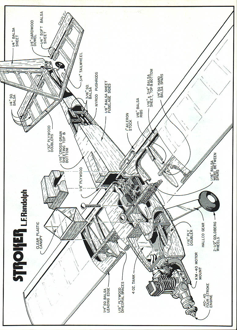
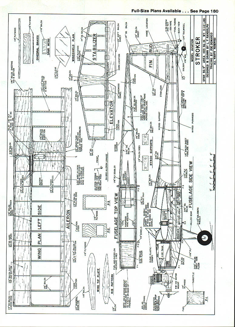
Stroker
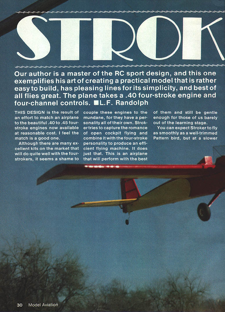
Our author is a master of RC sport design, and this one exemplifies his art of creating a practical model that is fairly easy to build, has pleasing lines for its simplicity, and—best of all—flies great. The plane takes a .40 four-stroke engine and four-channel controls.
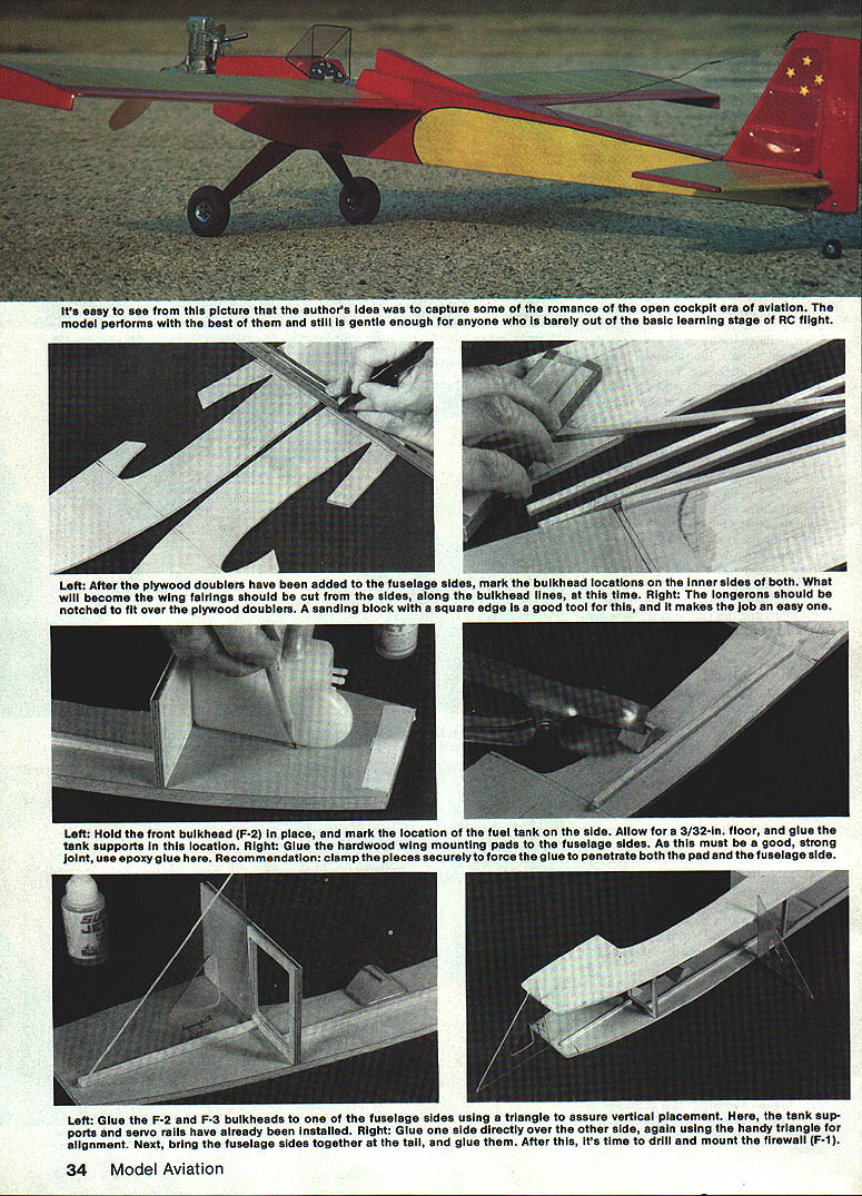
This design is the result of an effort to match an airplane to the beautiful .40–.45 four-stroke engines now available at reasonable cost. Although many excellent kits on the market will do quite well with four-strokers, it seemed a shame to couple these engines to the mundane. Stroker tries to capture the romance of open-cockpit flying and combine it with the four-stroke personality to produce an efficient flying machine. It performs with the best of them and is still gentle enough for those barely out of the learning stage.
If you don't yet have a four-cycle engine and like the looks of Stroker, it will also be quite happy with any hot .25 to sport .40 two-strokes, but you will need a 6–8 oz. tank to achieve similar flight time from a single filling. Construction is not ultra-simple, but it is not terribly difficult.
Specifications and general expectations
- Engine: .40–.45 four-stroke (or .25–.40 two-stroke alternative)
- Controls: four-channel (aileron, elevator, rudder, throttle)
- Handling: smooth, Pattern-like at slower speed; snaps require deliberate input
- Gear: conventional (taildragger), handles well on grass strips
- Power: four-stroke gives great sound and excellent fuel economy
Fuselage
- Slice the fuselage sides from opposite ends of a sheet of 1/8-in. balsa 9 in. wide, formed by edge-gluing three sheets of 1/8 × 3 × 36 together.
- Epoxy 1/16-in. plywood doublers to the inside of both sides. Tape the sides together and sand them to the same outline.
- Separate the sides and mark former locations on both sides. Glue on the longerons and uprights, servo rails, and tank mounts. Re-tape the sides and sand to the same outline.
- While taped together, drill the 1/4-in. wing-dowel holes and cut the front and rear cockpit fairings from the sides at the former locations; save the fairings for later.
Assemble the cabin and firewall:
- Cut the two cabin formers from 1/8-in. plywood. Glue them to one side using a triangle to assure perpendicular placement.
- Glue the other fuselage side to the formers, again checking alignment.
- Cut the firewall from 1/4-in. plywood. Drill for the engine mount and holes for fuel and throttle lines. Epoxy T-nuts to the back of the firewall for the engine-mount bolts, then glue the firewall in place.
- Bevel the sides at the tail, pull them together, and glue.
Landing gear and interior:
- Cut the landing-gear mount from 1/4-in. plywood and glue it in position against the front cabin former—flush with the bottom of the fuselage.
- Install the inner nylon (Nyrod) throttle line and nylon guides for the elevator and rudder.
- Fit and install the tank compartment floor from 1/8-in. balsa.
- If using nylon bolts for wing attachment, glue hardwood anchors to the fuselage sides; clamp well until the glue sets.
Bottom and top sheeting:
- Start the bottom fuselage sheeting with 1/16-in. plywood over the landing gear mount and at the tail-wheel location; finish with cross-grain 1/16-in. balsa.
- Install the fuel tank and lines, complete the top sheeting, and sand everything smooth.
- The headrest and cockpit fairings are finished later when fitting the wing.
Tail surfaces
- Cut two spar doublers 1/4-in. wide and 10 in. long from 1/16-in. plywood.
- Laminate one doubler to the center of the stabilizer (stab) trailing-edge spar; notch the other at the center so it will form easily to the leading-edge shape.
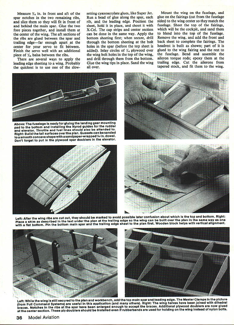
- Assemble the stab over the plan: pin down the trailing edge with its doubler, add the center sheet, the other ply doubler, and the leading edge. Cut ribs to fit between the leading and trailing edges.
- Include gussets at all corners to prevent wrinkling of the covering at these spots.
- Remove the stab from the plan, sand smooth, round the leading edge and tips, and sand the trailing edge just enough to remove sharpness.
Elevator and fin:
- Cut the elevator from 1/4-in. sheet balsa. Before cutting the rudder/elevator cutout, insert a 1/4-in. hardwood dowel at the center of the elevator leading edge.
- Tape the elevator to the trailing edge of the stab and sand both to match.
- Build the fin the same as the stab; construct the rudder to match and sand to fit. Provide a 1/4-in. half-round clearance in the rudder for the elevator dowel carry-through.
- Harden the areas where the control horns will be mounted.
- Add gussets; they can be sanded to a slight concave section with a sandpaper-wrapped dowel.
Wing
Ribs and jig:
- Cut ribs from fairly hard 1/16-in. sheet balsa—an ideal method is hand-sawing a stack of blanks.
- The airfoil is semi-symmetrical: build the wing so the trailing edge is slightly elevated when complete (for example, roughly 1/8 in. at the front edge of the trailing-edge sheet and up to about 1/2 in. at the back).
- Use a 1/2-in. balsa plank or scrap with the trailing-edge stock pinned to it as the jig.
Build the wing halves:
- Attach the trailing-edge support to the bench and lay the plan over it so the bench coincides with the trailing-edge on the plan.
- Build the wing as a flat-bottomed surface: pin the main spar flat against the bench and pin the trailing-edge sheet over the support.
- Add ribs—place the center ribs first or center-adjacent ribs as preferred—then the next ribs. Shear webs may be added as you go or after the ribs are in place.
- Glue a 1/32-in. sq. strip to the back edge of the trailing edge, add the top spar and leading edge.
- When glue has set, remove the wing from the bench and build the other half the same way on the back of the plan.
Joining halves and dihedral:
- Bevel the spars and the leading and trailing edges at the center to match the dihedral angle; join the halves with appropriate adhesive (Super Jet or equivalent).
- Trim 1/16 in. from both sides of the spar notches in the two ribs nearest the center to accept the dihedral braces. Glue the braces in place well into the trailing edge.
- Sand leading and trailing edges to blend into the ribs so sheeting flows smoothly.
Servo well and ailerons:
- Measure and cut space for the aileron servo between the spars as shown on the plan; finish the servo well with a 1/16-in. balsa spacer between ribs if needed.
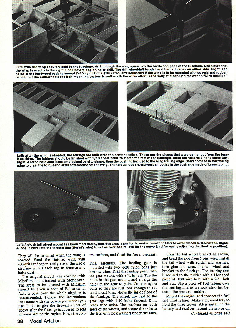
- Bend and assemble aileron torque rods; epoxy them at the trailing edge. Cut ailerons from tapered stock and fit to the wing.
Sheeting and finishing the wing:
- There are several ways to apply leading-edge sheeting; a slow-setting cyanoacrylate (e.g., Super Jet) with accelerator works well: run a bead along the spar and ribs, position the sheet, hold it and accelerate.
- Do the cap strips and center section in the same manner.
- Apply bottom sheeting next. With the bottom sheeting secure, drill through the bottom sheeting at the wing-bolt hole locations (before adding the top sheet).
- Inlay 1/16-in. plywood circles over the wing-bolt holes on the top of the wing and drill through them from the bottom. Glue the wing tips in place and sand the wing all over.
Wing attachment and final fitting
If using dowels and rubber bands for flying, you can omit the bolt work. If using 1/4-in., 20-thread nylon bolts, follow these steps:
- Place dowels in the holes previously drilled in the fuselage. Strap the wing to the fuselage with rubber bands so the spar passes exactly over the hardwood pads glued to the fuselage sides.
- Drill through the spars and pads with a 7/32-in. drill. Take care not to let the drill touch the plywood dihedral braces on either the top or bottom spar.
- Remove the wing and enlarge the holes through the spars with a 1/4-in. drill; the drill should just graze the dihedral braces.
- Glue additional 1/16-in. plywood braces to both sides of the spars at the center.
- Tap the hardwood pads with a 1/4-20 tap. Temporarily mount the wing to the fuselage with the nylon bolts and check the fit.
- Remember that thin layers of 1/16-in. balsa will be added to the top and bottom where the wing fits into the saddle to obtain the proper fit.
Fairings and final wing fit:
- Mount the wing on the fuselage and glue on the fairings (cut earlier from the fuselage sides) to the wing center so they match the fuselage.
- Sheet the tops of the fairings (cockpit area) and sand them to blend into the top of the fuselage.
- Remove the wing and add the front and back sheets to complete the fairings. The headrest is built as shown on the plans; part is glued to the wing fairing and the rest to the fuselage.
Covering and finishing
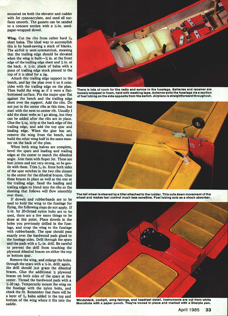
- Punch Monokote (or covering) paper where marked; iron it in place and use a sharp pen for alignment marks.
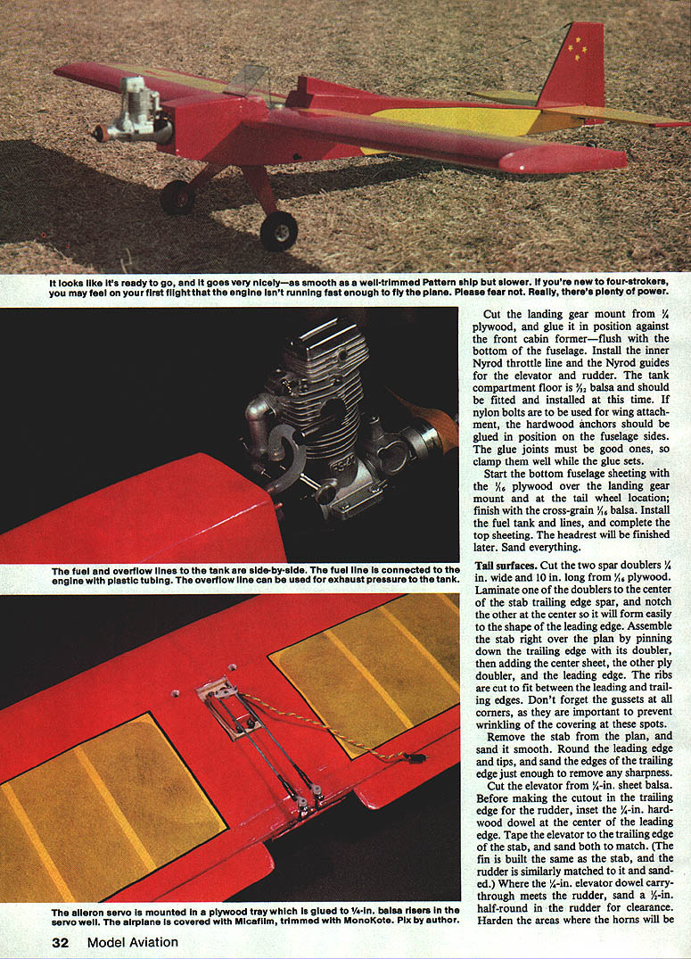
- The original model used Micafilm with Monokote trim. If using Micafilm, give the areas a coat of Balsarite—indeed, a coat over the whole airplane is recommended. Follow the covering-material manufacturer's instructions.
- After covering, give the firewall a coat of epoxy to seal around the engine cutout.
- Sand the finished wing with 400-grit and wipe the whole airframe with a tack rag to remove balsa dust.
- Hinge the control surfaces and check for free movement.
Final assembly
Landing gear and wheels:
- Mount the landing gear with two 1/4-20 nylon bolts (same as used for wing). Drill the landing gear and the gear mount with a 7/32-in. bit, tap the holes in the gear mount, and enlarge the holes in the gear legs to 1/4 in.
- Cut the nylon bolts so they extend about 1/2 in. above the inside floor of the fuselage.
- Wheels are held to the gear legs with 4-40 bolts through short pieces of 1/8-in. brass tube as axles. Use washers on both sides of the wheels and secure axle nuts with lock washers.
Tailwheel:
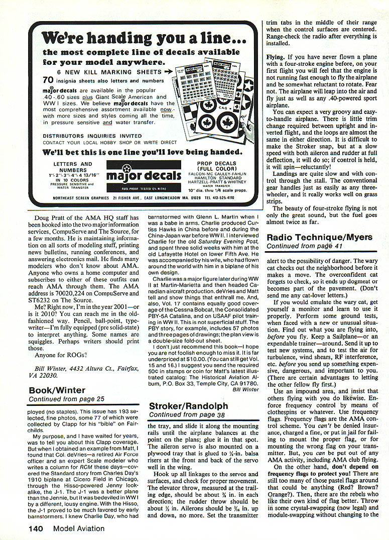
- Trim the tailwheel bracket as shown on the plans; bend the tailwheel axle from 1/16-in. wire.
- Install the tailwheel with solder and washers, then glue and screw the tailwheel bracket to the fuselage.
- The steering arm is secured to the rudder with a U-shaped piece of .030-in. wire held with a 2-56 bolt and nut. Slip a short piece of fuel tubing over the steering arm as a shock absorber between the arm and rudder.
Install radio, servos, and engine:
- Mount the engine and connect fuel and throttle lines. Use engine plastic tubing as desired for an exhaust-pressure-tank overflow.
- Make a plywood tray to hold the three servos. After installing the battery and receiver, mount the servos on the tray and slide it along the mounting rails until the airplane balances at the C.G. location shown on the plans; glue the tray in place.
- Mount the aileron servo on a plywood tray glued to balsa formers in the wing servo well.
- Hook up all linkages to the servos and control surfaces. Harden horn areas and check linkages for free movement.
Control throws (measured at trailing edge):
- Elevator: about 3/8 in. up and down
- Rudder: about 1/2 in.
- Ailerons: about 5/8 in. up and down (no more)
- Set transmitter trim tabs to center when surfaces are centered. Range-check the radio after installation.
Flying
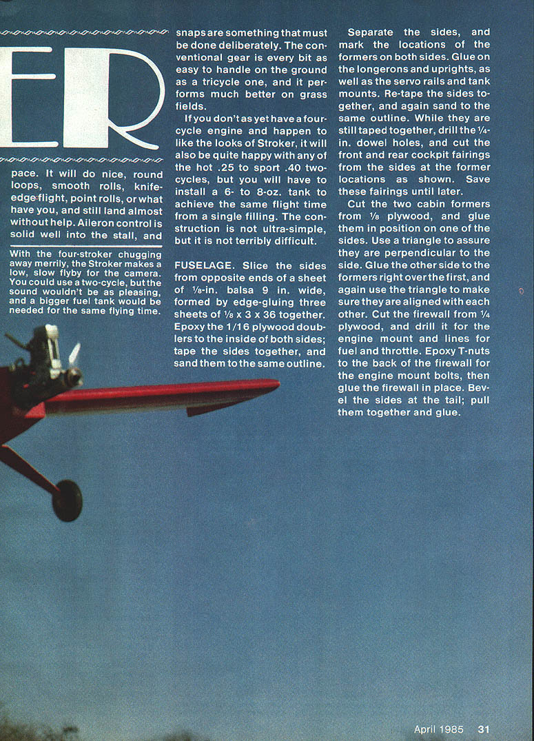
- On the first flight with a four-stroke you may feel the engine is not running fast enough and be reluctant to rotate. Do not fear: the airplane will leap into the air and fly as well as any .40-powered sport airplane.
- Expect a very groovy and easy-to-handle airplane. There is little trim change required between upright and inverted flight; loops are nearly the same in either direction.
- Stroker is reluctant to snap; at slow speed with both aileron and rudder at full deflection it will snap and, if held, will spin—reluctantly.
- Landings are fairly slow and controllable through the stall. Conventional gear is as easy to handle as a tricycle setup and works well on grass strips.
- The beauty of four-stroke flying is the great sound and the increased fuel economy—the fuel goes almost twice as far.
Transcribed from original scans by AI. Minor OCR errors may remain.

