
Structural Design
A. G. Lennon
Editor's note
This two‑part article was reviewed for technical content by noted modeler and engineer Gil Morris. Per that review, modifications have been made to the original text. The author was provided a copy of the review and was asked to consider revising the text; he declined.
Where appropriate, I have included Morris' comments in italics. They are presented to allow the reader to form his own judgments and are not intended to polarize the discussion.
Please see "The Haught Corner" for a full discussion of this presentation.
Early full‑scale aircraft structures
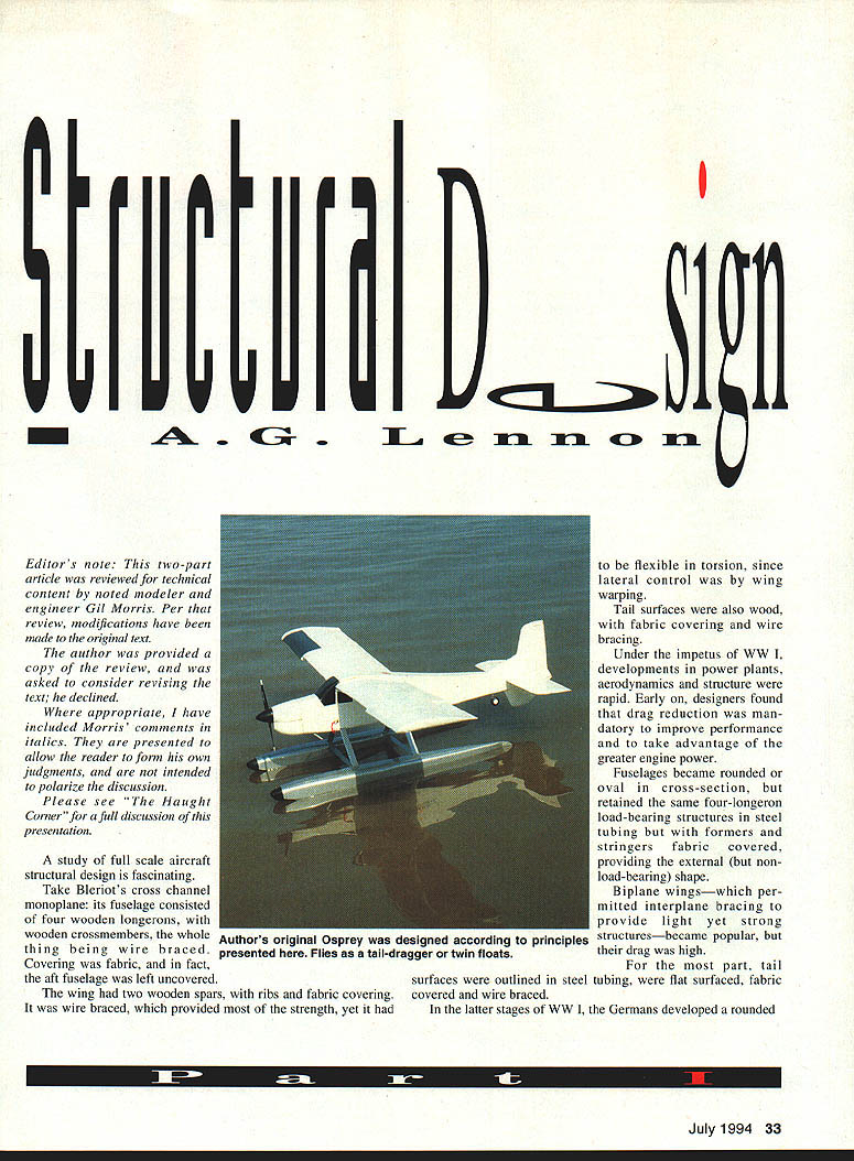
A study of full‑scale aircraft structural design is fascinating.
Take Bleriot's cross‑channel monoplane: its fuselage consisted of four wooden longerons with wooden crossmembers, the whole thing being wire braced. Covering was fabric, and in fact the aft fuselage was left uncovered.
The wing had two wooden spars with ribs and fabric covering. It was wire braced, which provided most of the strength, yet it had to be flexible in torsion since lateral control was by wing warping.
Tail surfaces were also wood, with fabric covering and wire bracing.
World War I developments
Under the impetus of World War I, developments in power plants, aerodynamics and structure were rapid. Early on, designers found that drag reduction was mandatory to improve performance and to take advantage of the greater engine power.
Fuselages became rounded or oval in cross‑section but retained the same four‑longeron load‑bearing structure in steel tubing with formers and stringers; fabric covered to provide the external (but non‑load‑bearing) shape.
Biplane wings — which permitted interplane bracing to provide light yet strong structures — became popular, though their drag was high.
For the most part, tail surfaces were outlined in steel tubing, were flat surfaced, fabric covered and wire braced.
Stress‑skinned wooden structures
In the latter stages of World War I, the Germans developed a rounded all‑plywood fuselage. Plywood skin provided a low‑drag external shape and also absorbed structural loads, thus locating material far from the neutral axis. A light yet strong stress‑skinned structure was achieved.
The Fokker D.VIII high‑wing monoplane introduced a cantilever wing too. Its wooden structure was plywood skinned, much greater in thickness than contemporary biplane wings. With other struts holding the wing above the fuselage, no drag‑producing external bracing was required — it was stress‑skinned.
As Allied air forces found the Fokker D.VIII a formidable adversary, Lockheed in the U.S. and de Havilland in Great Britain produced plywood stress‑skinned aircraft during the 1930s. Lindbergh's Lockheed Sirius is a classic example; in World War II the de Havilland Mosquito was an outstanding wooden aircraft.
Four‑longeron fuselages, externally braced wings and metal‑tube tail surfaces survive in such aircraft as the Beech Staggerwing and Piper Cub; ultralights follow that tradition.
Transition to metal and composites
What followed was the gradual swing to all‑metal stress‑skinned aircraft structures. Today, aircraft produced in quantity follow this design: Piper, Beech, Cessna, Boeing, McDonnell Douglas and Lockheed are examples.
In the 1970s the use of composite materials came to prominence, pioneered by German glider manufacturers and by Burt Rutan. The VariEze, Long-EZ and finally the spectacular Voyager and Beech Starship (canard) are outstanding examples.
- Common composite materials: fiberglass, epoxy, foam, carbon and boron fibers, Aramid, Nomex.
- Typical benefits: replacing metal, especially in the sportplane field under the stimulus of the Experimental Aircraft Association; aircraft provide outstanding performance with modest horsepower.
- Structural principle: locate material in structures far from the neutral axis where possible.
Neutral axis and basic concepts
Now, what is this neutral axis business about? A basic acquaintance with tension, compression, torsion/shear and bending will serve as an introduction.
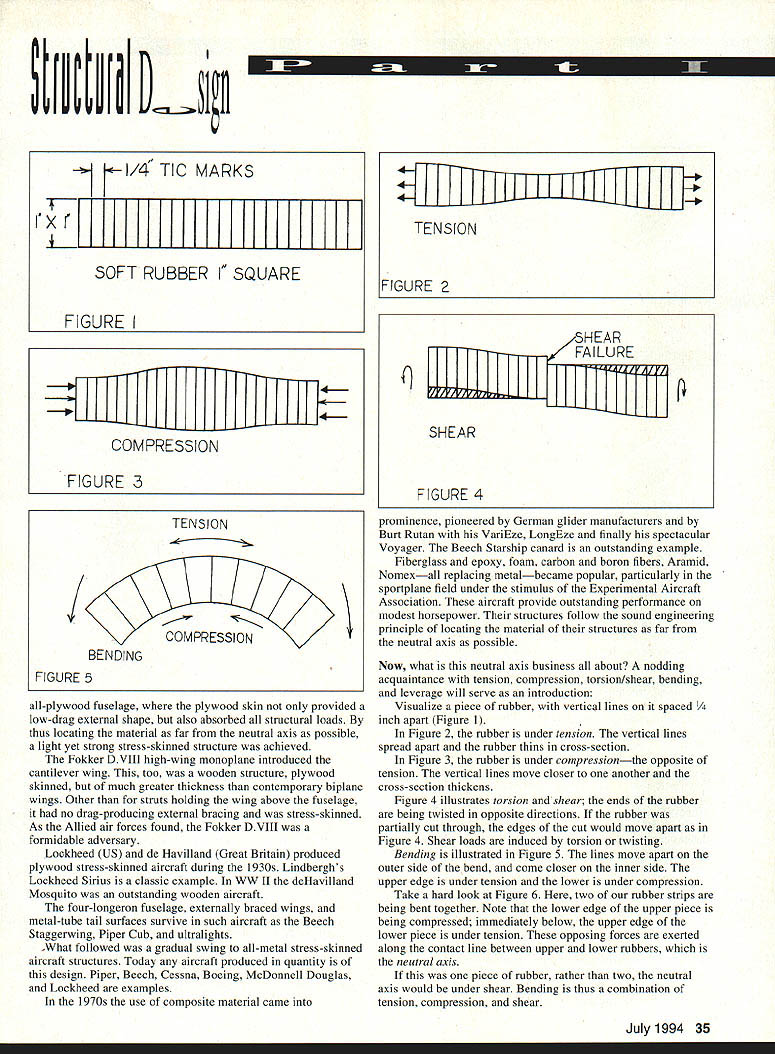
Visualize a piece of rubber with vertical lines spaced an inch apart.
- When the rubber is under tension, the vertical lines spread apart and the rubber thins in cross‑section.
- When the rubber is under compression the opposite occurs: the vertical lines move closer and the cross‑section thickens.
Figure 4 illustrates torsion/shear — the ends of the rubber being twisted in opposite directions; if the rubber were partially cut through at the edges the cuts would move apart. Shear loads induce torsion (twisting).
Bending is illustrated: lines move apart on the outer side of the bend and come closer on the inner side; the upper edge is under tension while the lower is under compression.
Take a hard look at two rubber strips being bent together. Note the lower edge of the upper piece being compressed; immediately below that contact line the lower piece is under tension. These opposing forces are exerted along the contact line between upper and lower rubbers, which is the neutral axis.
If this was one piece of rubber rather than two, the neutral axis would be under shear. Bending is thus a combination of tension, compression and shear.
*Morris: "the neutral axis is intersected by the neutral surface; the neutral axis is in the cross‑section of the piece of rubber."*
Leverage and bending moments
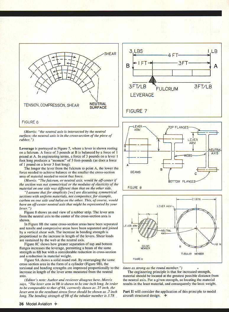
Leverage is portrayed in Figure 7, where a lever is shown resting on a fulcrum. A force of 3 pounds at B is balanced by a force of 1 pound at A. In engineering terms, a force of 3 pounds on a lever 1 foot long produces a "moment" of 3 foot‑pounds (as does a force of 1 pound on a lever 3 feet long).
The longer the lever from the fulcrum to point A, the lower the force needed to achieve balance, or the smaller the cross‑sectional area of material needed to resist that force.
*Morris: "The fulcrum, or neutral axis, would be off‑center if the section was not symmetrical or the modulus of elasticity of the material on one side was different than that on the other side.
"I assume that for simplicity [we] are discussing symmetrical sections with uniform materials, not composites; for example, carbon on one side and balsa on the other. This, of course, would have an off‑center neutral axis that might be represented by your lever."*
Figure 8 — section shapes and shear webs
Figure 8 shows an end view of a rubber strip. The lever arm from the neutral axis to the center of the cross‑section area is shown.
In Figure 8B the same cross‑section areas have been separated and tensile and compressive areas have been separated and joined by a vertical shear web. The increase in bending strength is proportional to the increase in length of the levers. Shear loads are sustained by the web at the neutral axis.
Figure 8C shows how greater separation of top and bottom flanges increases the leverage, permitting a beam of the same strength as 8B but with a considerable reduction in cross‑section and a reduction in material weight.
Figure 9 — solid rod versus tube
Figure 9A shows a solid round rod. By rearranging the same cross‑section area in the form of a cylinder (Figure 9B), the torsional and bending strengths are improved proportionally to the increase in length of the lever arms measured from the neutral axis.
(Editor's note: Author and reviewer disagree here.)
*Morris: "The lever arm of 9B is shown to be one inch long. In order to be comparable to that of 9A, correctly shown as .25 inch, the lever arm to the resultant stress force should be shown as .7 inch long. The bending strength of 9B of the tubular member is 3.78 times as strong as the round member.")*
Engineering principle and conclusion
The engineering principle is that for increased strength, material should be located at the greatest possible distance from the neutral axis. For a given strength, so locating the material results in the least material and consequently the least weight.
Part II will consider the application of this principle to model aircraft structural design.
Transcribed from original scans by AI. Minor OCR errors may remain.

