
Structural Design
A. G. Lennon
Editor's note
As with Part I, Gil Morris handled technical review of this piece. I have included his comments where appropriate.
Introduction
In this part, actual structural designs are illustrated, based on the engineering principle (outlined in Part I) of locating material as far from the neutral axis as possible.
Consider the inflight forces involved for the various aircraft components: fuselage, wing, horizontal and vertical tail surfaces, and landing gear.
Fuselage
For powered RC models, the fuselage is probably the most heavily stressed item. It must absorb thrust and torque loads from the engine; bending loads from weights of engine, receiver, servos, battery, and rudder or elevator action; and twisting loads as the ailerons are operated. These are exaggerated by centrifugal loads as the model banks, pulls out of a dive, or pulls up sharply. The fuselage-mounted landing gear, either tricycle or tail-dragger, imposes heavy loads, particularly on hard landings.
The best overall structure for the fuselage is a cylinder—suitably reinforced where cutouts for wings, canopy, etc. are involved. Such a rounded fuselage is not difficult to produce in fiberglass and epoxy; many are made this way. The "as far from the neutral axis as possible" philosophy is closely followed, and few bulkheads are required.
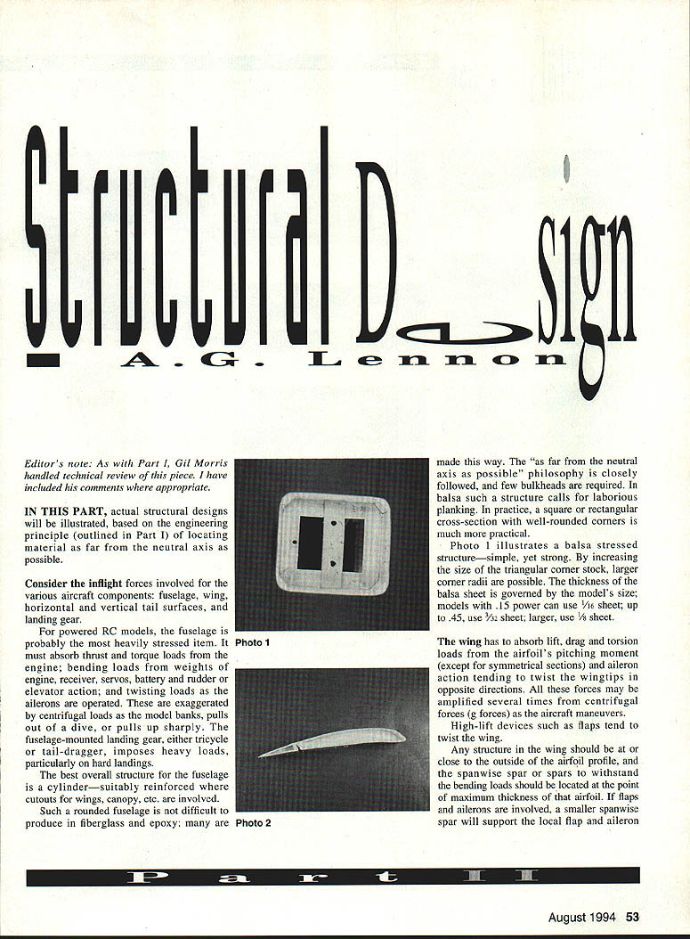
In balsa such a structure calls for laborious planking. In practice, a square or rectangular cross-section with well-rounded corners is much more practical.
Photo 1 illustrates a balsa stressed structure—simple, yet strong. By increasing the size of the triangular corner stock, larger corner radii are possible. The thickness of the balsa sheet is governed by the model's size:
- Models with .15 power can use 1/16" sheet.
- Up to .45 power, use 3/32" sheet.
- Larger models, use 1/8" sheet.
The cutouts for wing and canopy need to be reinforced by internal doublers, and these should be provided for fuselage-mounted, bolted-on aluminum landing gear.
Wing
The wing has to absorb lift, drag and torsion loads from the airfoil's pitching moment (except for symmetrical sections) and aileron action tending to twist the wingtips in opposite directions. All these forces may be amplified several times by centrifugal forces (g forces) as the aircraft maneuvers.
High-lift devices such as flaps tend to twist the wing.
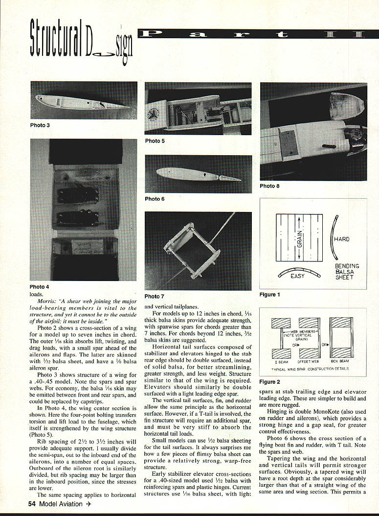
Any structure in the wing should be at or close to the outside of the airfoil profile. The spanwise spar or spars to withstand bending loads should be located at the point of maximum thickness of that airfoil. If flaps and ailerons are involved, a smaller spanwise spar will support the local flap and aileron.
Photo 2 shows a cross-section of a wing for a model up to seven inches in chord. The outer 1/16" skin absorbs lift, twisting, and drag loads, with a small spar ahead of the ailerons and flaps. The latter are skinned with 1/32" balsa sheet, and have a 1/8" balsa aileron spar.
Photo 3 shows the structure of a wing for a .40–.45 model. Note the spars and spar webs. For economy, the balsa 1/16" skin may be omitted between front and rear spars, and could be replaced by capstrips.
Photo 4 shows the wing center section. Here the four-point bolting transfers torsion and lift load to the fuselage, which itself is strengthened by the wing structure.
Rib spacing of 2½" to 3½" will provide adequate support. I usually divide the semi-span, out to the inboard end of the ailerons, into a number of equal spaces. Outboard of the aileron root it is similarly divided, but rib spacing may be larger than in the inboard position, since the stresses are lower.
The same spacing applies to horizontal and vertical tailplanes.
For models up to 12" in chord, 1/16" thick balsa skins provide adequate strength, with spanwise spars for chords greater than 7". For chords beyond 12", 3/32" balsa skins are suggested.
Tail surfaces
Horizontal tail surfaces composed of stabilizer and elevators hinged to the stab rear edge should be double surfaced, instead of solid balsa, for better streamlining, greater strength, and less weight. Structure similar to that of the wing is required. Elevators should similarly be double surfaced with a light leading edge spar.
The vertical tail surfaces—fin and rudder—use the same principle as the horizontal surface. However, if a T-tail is involved, the fin structure will require an additional spar and must be very stiff to absorb the horizontal tail loads.
Small models can use 1/32" balsa sheeting for the tail surfaces. It always surprises me how a few pieces of flimsy balsa sheet can provide a relatively strong, warp-free structure.
Early stabilizer-elevator cross-sections for a .40-sized model used 1/8" balsa with reinforcing spars and plastic hinges. Current structures use 1/16" balsa sheet, with light spars at the stab trailing edge and elevator leading edge. These are simpler to build and are more rugged.
Hinging is double MonoKote (also used on rudder and ailerons), which provides a strong hinge and a gap seal, for greater control effectiveness.
Tapering
Tapering the wing and the horizontal and vertical tails will permit stronger surfaces. Obviously, a tapered wing will have a root depth at the spar considerably larger than that of a straight wing of the same area and wing section. This permits a stronger inboard spar, allowing a lighter outboard structure.
Particularly if the spars are tapered. For example, a spar upper flange 1/2" x 1/4" on a 12" root chord can be reduced to 1/4" x 1/8" for an eight-inch tip chord.
In addition to increased spar depth, the wing skins are further from the neutral axis at the root, adding to the wing's strength at the point of greater stress, thus permitting higher aspect-ratio wings. Similar comments apply to vertical and horizontal tailplanes.
Tapered surfaces have their drawbacks, however:
- The tips will operate at lower Reynolds numbers, and lower efficiency with the danger of wingtip stall.
- Each rib being different increases the time to design the structure.
- Construction is more complex.
Landing gear
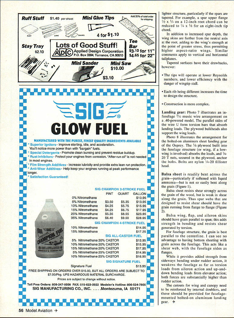
Photo 7 illustrates an in-fuselage 5/32" music wire arrangement on a .40-powered model. The parallel sides of the wire U form torsion bars that absorb landing loads. The plywood bulkheads also support the wing loads.
Photo 8 illustrates the arrangement for the bolted-on aluminum sheet landing gear of the Osprey. The 3/4" plywood built into the fuselage structure (or wing, if a low wing is involved) absorbs the loads, and 1/4-20 T-nuts, secured in the plywood, anchor the axles. Bolts are nylon 1/4-20 fillister head.
Balsa grain and sheeting
Balsa sheet is readily bent across the grain—particularly if softened with liquid ammonia—but is not so easily bent along the grain (Figure 1).
Balsa sheet resists shear strongly across the grain of the wood, but is weak in shear along the grain. Thus spar webs that are designed to resist shear should have the grain running from flange to flange (Figure 2).
Balsa wing, flap, and aileron skins should have the grain parallel to the span; this adds strength in bending and resists shear generated by torsion.
For fuselage structure, the grain is best parallel to the centerline. There is no advantage to having bottom sheeting with grain across the fuselage. This acts like a shear web, with the fuselage sides as flanges. While it provides added strength from sideways bending under rudder action, it weakens the fuselage as far as torsion loads from aileron action and up-and-down bending loads from elevator action; both forces are substantially higher than rudder action.
Transcribed from original scans by AI. Minor OCR errors may remain.

