
STUKA STUNT
Barry Baxter
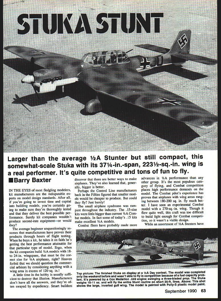
Larger than the average 1/2A stunter but still compact, this somewhat-scale Stuka with its 37-1/4-in. span and 223-1/2 sq. in. wing is a real performer. It's quite competitive and tons of fun to fly.
In the eyes of most fledgling modelers, kit manufacturers are the indisputable experts on model design standards. After all, if you're going to invest time and capital into building models, you're certainly going to make sure they're thoroughly tested and that they deliver the best possible performance. Surely kit companies wouldn't produce second-rate equipment — or would they?
The average beginner unquestioningly assumes that manufacturers have proven their products through hours of flight testing. When he buys a kit, he takes it on faith he's getting the best performance attainable for that particular type of model. Ergo, when the kit companies build 1/2A models with 18- to 24-in. wingspans, that must be the correct size for 1/2A airplanes, right? Heaven forbid we should question the commercial arbiters by considering anything with a wing area in excess of 120 sq. in.!
A little time in the hobby is usually sufficient to destroy that illusion. Manufacturers don't have all the answers, and they're often swayed by expediency. Smart builders discover that there are better ways to make airplanes. They've also learned that, generally, bigger is better.
Perhaps the control-line manufacturers back in the Fifties figured that smaller models would be cheaper to produce. But could they fly? Just barely. The small-airplane syndrome was rampant throughout the industry. The .15-size kits were little bigger than current 1/2A Combat models. In fact, some of today's .15 kits make excellent 1/2A ships.
Combat fliers have probably made more advances in 1/2A performance than any other group. It's the most populous category of flying, and Combat competition places high performance demands on the model. The Combat pilot's experience has shown that airplanes with wing areas ranging between 180–200 sq. in. fly much better. I have seen an experimental Combat model with a 270-sq.-in. wing. Though it flew quite well, this craft was too difficult to build light enough for Combat competition, so it wasn't a viable design.
While an assortment of 1/2A Stunters has appeared — including some outstanding designs featured in magazines from time to time — none has gained universal acceptance. Part of the problem is that control-line fliers have never seen really good-flying 1/2As. No doubt you recall miserable ready-to-fly models; probably the single biggest reason people shun control-line flying. Solid-wood kits weren't much better. If you've never seen a small model that can really carve the air, you've missed some exciting flying-machine performance. Here's a chance to catch up.
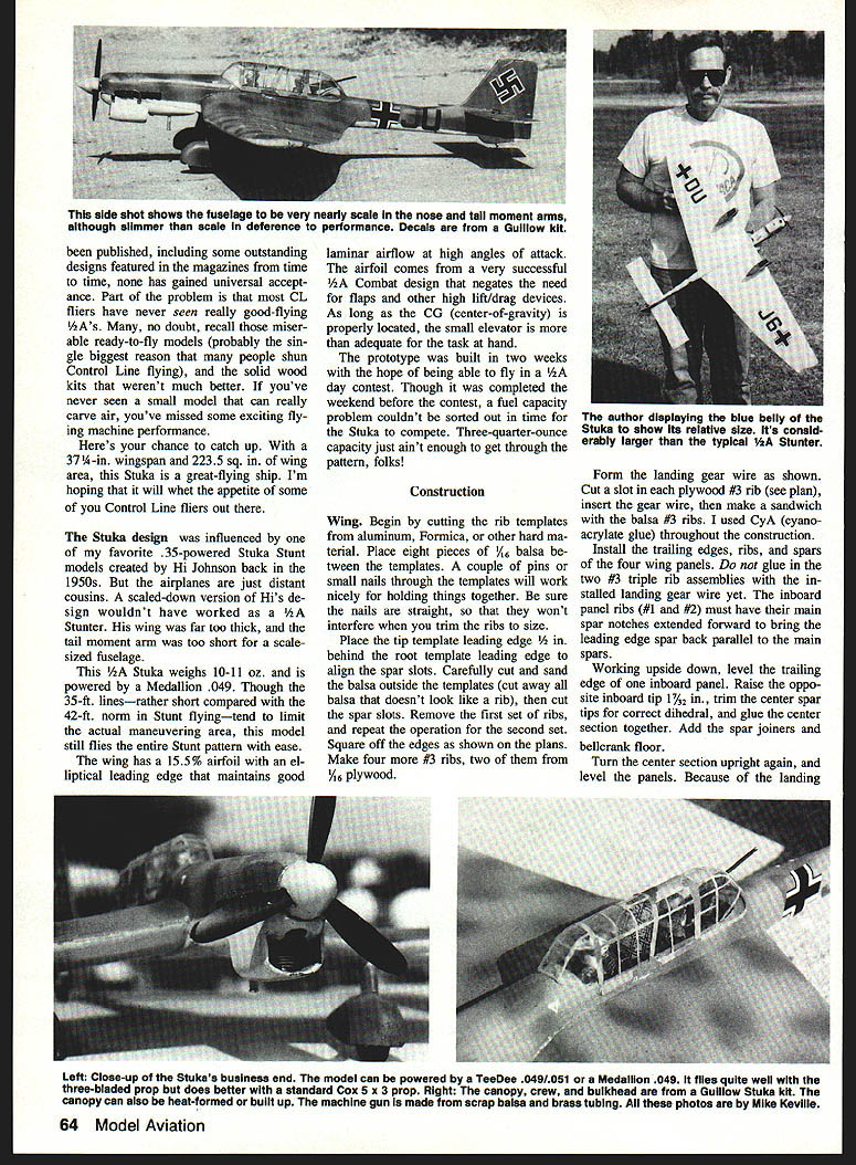
The 37-1/4-in. wingspan, 223-1/2-sq.-in. Stuka is a great-flying ship I'm hoping will whet the appetite of some control-line fliers. The Stuka design was influenced by the favorite 35-powered Stuka Stunt models created by Hi Johnson back in the 1950s. The airplanes are just distant cousins — scaled-down versions of the design wouldn't have worked. A 1/2A Stunter wing would be far too thick and the tail moment arm too short for a scaled-down fuselage.
A 1/2A Stuka weighs 10–11 oz. when powered by a Medallion .049. Though 35-ft lines — rather short compared to the 42-ft norm for stunt flying — tend to limit the actual maneuvering area, the model still flies the entire Stunt pattern with ease. The wing has a 15.5% airfoil; the elliptical leading edge maintains good laminar airflow at high angles of attack. The airfoil is a very successful Combat design and negates the need for flaps or other high-lift/drag devices. As long as the CG (center of gravity) is properly located, a small elevator is adequate for the task.
I had the prototype built in two weeks and was hoping to be able to fly it the day of a contest. Though completed the weekend before the contest, a fuel-capacity problem couldn't be sorted out in time, so the Stuka couldn't compete. A 3/4-oz. tank just wasn't enough to get through the pattern.
Construction
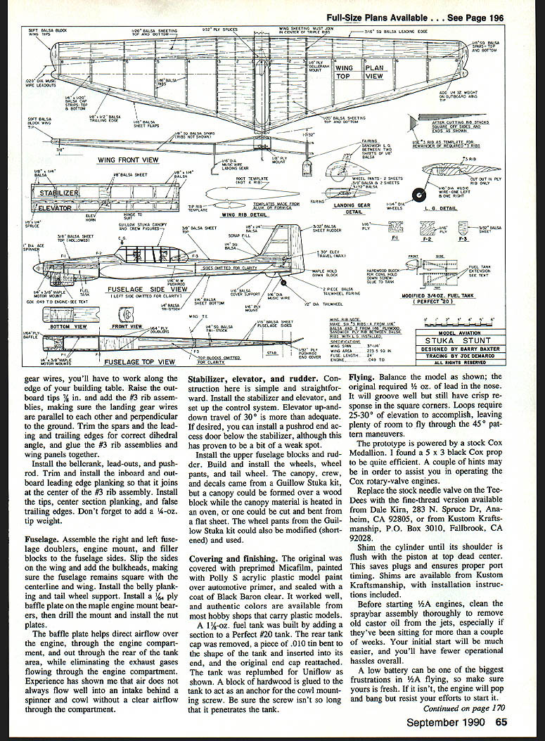
Wing
Begin by cutting rib templates from aluminum, Formica or other hard material. Place eight pieces of .016 balsa between the templates; a couple of pins or small nails through the templates will hold things together. Make sure the pins or nails are straight and won't interfere with trimming the ribs to size.
Place the tip template leading edge 1/8 in. behind the root template leading edge to align the spar slots. Carefully cut and sand the balsa outside the templates — cut away all the balsa that doesn't look like a rib — then cut the spar slots. Remove the first set of ribs and repeat the operation for the second set. Square off the edges as shown on the plans. Make four more #3 ribs, two of them from 1/16 plywood.
Form the landing-gear wire as shown on the plans. Cut a slot in each plywood #3 rib, insert the gear wire, then make a sandwich with the balsa #3 ribs. Use cyanoacrylate (CA) glue throughout the construction if desired.
Install the trailing edges, jigs, ribs, and spars on the two wing panels. Do not glue in the two #3 triple-rib assemblies with the installed landing-gear wire yet. The inboard panel ribs (#1 and #2) must have their spar notches extended forward to bring the leading-edge spar back parallel to the main spars.
Working upside down, level the trailing edge of the inboard panel. Raise the opposite inboard tip 1-3/8 in., trim the center-spar tips for correct dihedral, and glue the center section together. Add the spar joiners and bellcrank floor.
With the gear wires installed, you'll have to work along the edge of your building table. Raise the outboard tips 2 in. and add the #3 rib assemblies, making sure the landing-gear wires are parallel to each other and perpendicular to the ground. Trim the spars and the leading and trailing edges for the correct dihedral angle, and glue the #3 rib assemblies and wing panels together.
Install the bellcrank, lead-outs, and pushrod. Trim and install the inboard and outboard leading-edge planking so that it joins at the center of the #3 rib assembly. Install the tips, center-section planking, and false trailing edges. Don't forget to add a 1/4-oz. tip weight.
Fuselage
Assemble the right and left fuselage doublers, engine mount, and filler blocks to the fuselage sides. Slip the sides on the wing and add the bulkheads, making sure the fuselage remains square with the centerline and wing. Install the belly planking and tail-wheel support. Install a 1/4-in. baffle plate onto the maple engine-mount bearers, then drill the mounting holes and install the nut plates.
The baffle plate helps direct airflow over the engine, through the engine compartment, and out through the rear of the tank area, while preventing exhaust gases from flowing through the engine compartment. Experience has shown that air does not always flow well into an intake behind a spinner and cowl without a clear airflow through the compartment.
Stabilizer, elevator, and rudder
Construction here is simple and straightforward. Install the stabilizer and elevator, and set up the control system. Elevator up-and-down travel of 30° is more than adequate. If desired, you can install a pushrod and access door below the stabilizer, although this has proven to be a bit of a weak spot. Install the upper fuselage blocks and rudder. Build and install the wheels, wheel pants, and tail wheel.
The canopy, crew, and decals came from a Guillow Stuka kit, but a canopy could be formed over a wood block while the canopy material is heated in an oven, or one could be cut and bent from a flat sheet. The wheel pants from the Guillow Stuka kit could also be modified (shortened) and used.
Covering and finishing
The original was covered with preprimed Micafilm, painted with Polly-S acrylic plastic model paint over automotive primer, and sealed with a coat of Black Baron clear. It worked well, and authentic colors are available from most hobby shops that carry plastic models.
A 1-1/2-oz. fuel tank was built by adding a section to a Perfect #20 tank. The rear tank cap was removed, a piece of .010 tin bent to the shape of the tank and inserted into the ends, and the original end cap reattached. The tank was replumbed for uniflow as shown on the plans. A block of hardwood is glued to the tank to act as an anchor for the cowl-mounting screw. Be sure the screw isn't so long that it penetrates the tank.
Flying
Balance the model as shown on the plans; the original required 1/2 oz. of lead in the nose. It will groove well but still have crisp response in the square corners. Loops require 25–30° of elevator to accomplish, leaving plenty of room to fly through the 45° pattern maneuvers.
The prototype is powered by a stock Cox Medallion .049. I found a 5 x 3 black Cox prop to be quite efficient.
A couple of operational hints:
- Replace the stock needle valve on Tee-Dees with the fine-thread version available from Dale Kirn, 283 N. Spruce Dr., Anaheim, CA 92805, or from Kustom Kraftsmanship, P.O. Box 3010, Fallbrook, CA 92028.
- Shim the cylinder until its shoulder is flush with the piston at top dead center. This saves plugs and ensures proper port timing. Shims are available from Kustom Kraftsmanship, with installation instructions included.
- Before starting 1/2A engines, clean the spraybar assembly thoroughly to remove old castor oil from the jets, especially if they've been sitting for more than a couple of weeks. Your initial start will be much easier, and you'll have fewer operational hassles overall.
- A low battery can be one of the biggest frustrations in 1/2A flying, so make sure yours is fresh. If it isn't, the engine will pop and bang but resist your efforts to start it.
Conclusion
Maybe you want a weekend flier. Maybe you want a model that'll leave you with a smile on your face when those 1/2A day contests arrive. Or maybe you want both. Off the contest trail or on, the Stuka is guaranteed to be one of the most unusual 1/2A Stunt ships around — and one of the ablest fliers. This one is designed to win!
Transcribed from original scans by AI. Minor OCR errors may remain.

