
Stuntfire 60
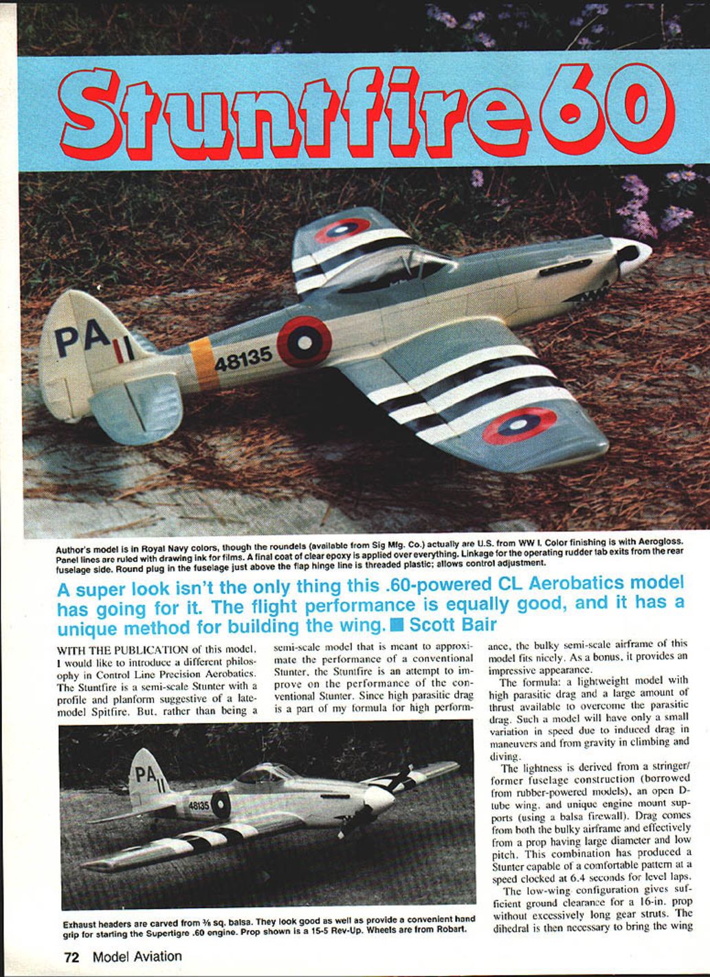
A super look isn't the only thing this .60-powered CL aerobatics model has going for it. The flight performance is equally good, and it has a unique method for building the wing. — Scott Bair
With the publication of this model, I would like to introduce a different philosophy in control-line precision aerobatics. The Stuntfire is a semi-scale stunter with a profile and planform suggestive of a late-model Spitfire. Rather than being a semi-scale model meant simply to approximate the performance of a conventional stunter, the Stuntfire is an attempt to improve on that performance. Because high parasitic drag is part of my formula for high performance, the bulky semi-scale airframe of this model fits nicely. As a bonus, it provides an impressive appearance.
The formula: a lightweight model with high parasitic drag and a large amount of available thrust to overcome that drag. Such a model will have only a small variation in speed due to induced drag in maneuvers and from gravity in climbing and diving.
Lightness is achieved with a stringer-and-former fuselage construction (borrowed from rubber-powered models), an open D-tube wing, and unique engine-mount supports (a balsa firewall arrangement). Drag is produced by the bulky airframe and by using a large-diameter, low-pitch prop. This combination has yielded a stunter capable of a comfortable pattern at a speed clocked at 6.4 seconds per level lap.
The low-wing configuration provides sufficient ground clearance for a 16-in. prop without excessively long gear struts. Dihedral is necessary to bring the wing tips to the proper flying attitude. The low-wing mounting also allows the tank to be mounted partly over the wing leading edge, reducing CG change as fuel is burned. This configuration also puts the engine air intake high above the ground, reducing the chance of ingesting dirt.
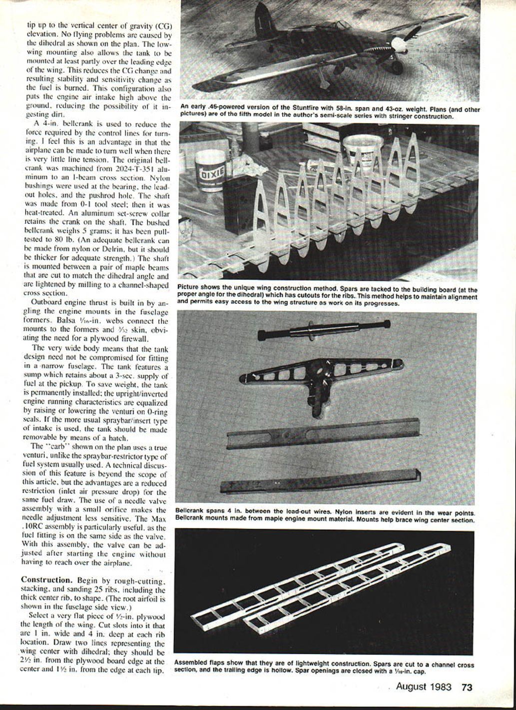
A 4-in. bellcrank is used to reduce the force required to turn; it gives a nice feel to the controls and allows the airplane to turn well with very little line tension. The original bellcrank was machined from 2024-T351 aluminum in an I-beam cross section. Nylon bushings are used at the bearing and leadout holes. The pushrod shaft is made from O-1 tool steel, heat-treated; an aluminum set-screw collar retains the crank on the shaft. The bushed bellcrank weighs 5 grams and has been pull-tested to 80 lb. An adequate bellcrank can also be made from nylon or Delrin but should be thicker for adequate strength. The shaft is mounted between a pair of maple beams cut to match the dihedral angle and lightened by milling a channel-shaped cross section.
Outboard engine thrust is built in by angling the engine mounts in the fuselage formers. Balsa 1/16-in. webs connect the mounts to the formers and 1/32-in. skin, obviating the need for a plywood firewall.
The wide fuselage simplifies tank design. The tank features a sump that retains about a three-second supply at the pickup. To save weight the tank may be permanently installed upright; inverted running characteristics are equalized by raising or lowering the venturi. O-ring seals are used on the spraybar/insert-type intake if that system is chosen; if so, make the tank removable by a hatch.
The carburetor shown on the plan uses a true venturi, unlike the usual spraybar-restrictor type. The advantages include reduced inlet restriction (less pressure drop) for the same fuel draw. Using a needle-valve assembly with a small orifice makes needle adjustment less sensitive. A max-flow assembly with the fuel fitting on the same side as the valve is particularly useful; the valve can be adjusted after starting the engine without reaching over the airplane.
Construction
- Prepare the wing ribs:
- Rough-cut, stack and sand 25 ribs, including the thicker center rib.
- Shape the root airfoil as shown on the plan.
- Fuselage jig and dihedral:
- Select a very flat piece of 1/2-in. plywood the length of the wing for a building board.
- Cut slots 1/4-in. wide and 1/4-in. deep for rib locations.
- Draw two lines representing the wing center and establish the dihedral on the plywood board. These lines should be 2½ in. from the board edge at the center and 1½ in. from the edge at each tip.
- Tip up to the vertical center-of-gravity (CG) elevation as shown on the plan. The dihedral as shown causes no flying problems.
- Wing assembly:
- Temporarily glue the top and bottom spars to the board, equally spaced about the centerline. For accuracy, measure the spacing from your rib stack.
- Glue the ribs to the spars with the forward ends down, then add the trailing-edge cap and sheet the trailing edge.
- Remove the wing and turn it over on the board (ribs should now be nose-up). Bend and attach a wet triangular leading edge to the nose of the ribs, then sheet the leading edge.
- Add the bellcrank and landing-gear blocks (Sig blocks allow the gear to be removed). Next, sheet the wing center section. Warps can be removed by twisting the wing as each piece of center sheeting is added.
- Build and attach the flaps, add the bellcrank-to-flap pushrod and horns (two ordinary horns can be cut in place of the ones shown on the plan).
- At this point the wing should weigh about 6–7 oz.
- Cover wing panels with medium silkspan; the rest of the model is covered with 00 silkspan. Keep paint to a minimum.
- Tank:
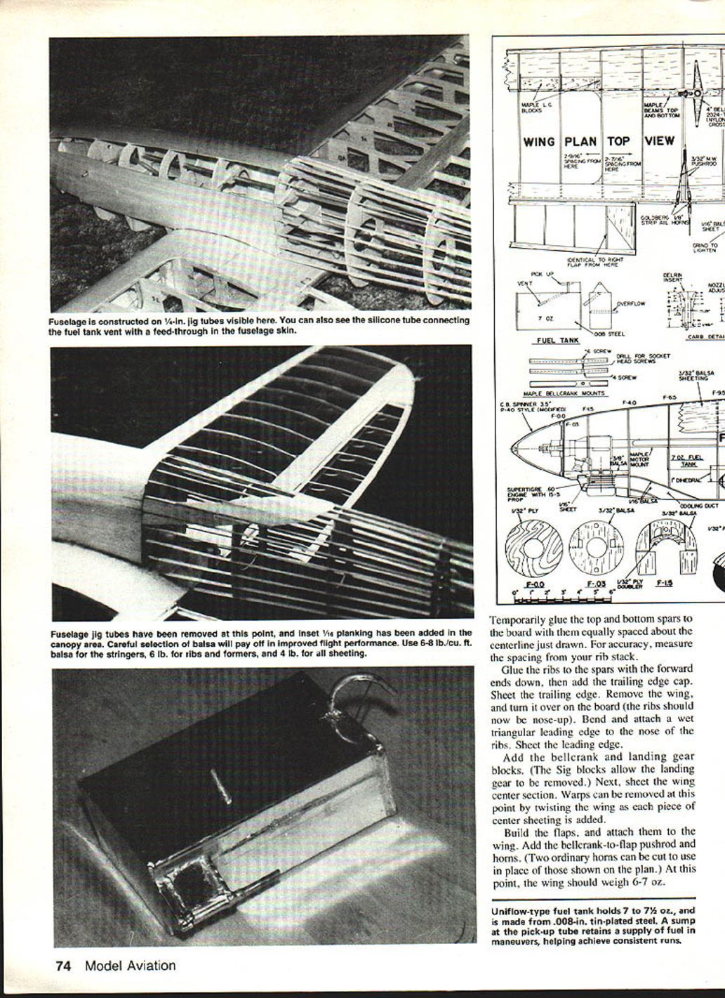
- The uniflow-type fuel tank holds 7 to 7½ oz. and is made from .008-in. tin-plated steel. The sump at the pickup retains fuel during maneuvers, helping achieve consistent runs.
- Fuselage and engine installation:
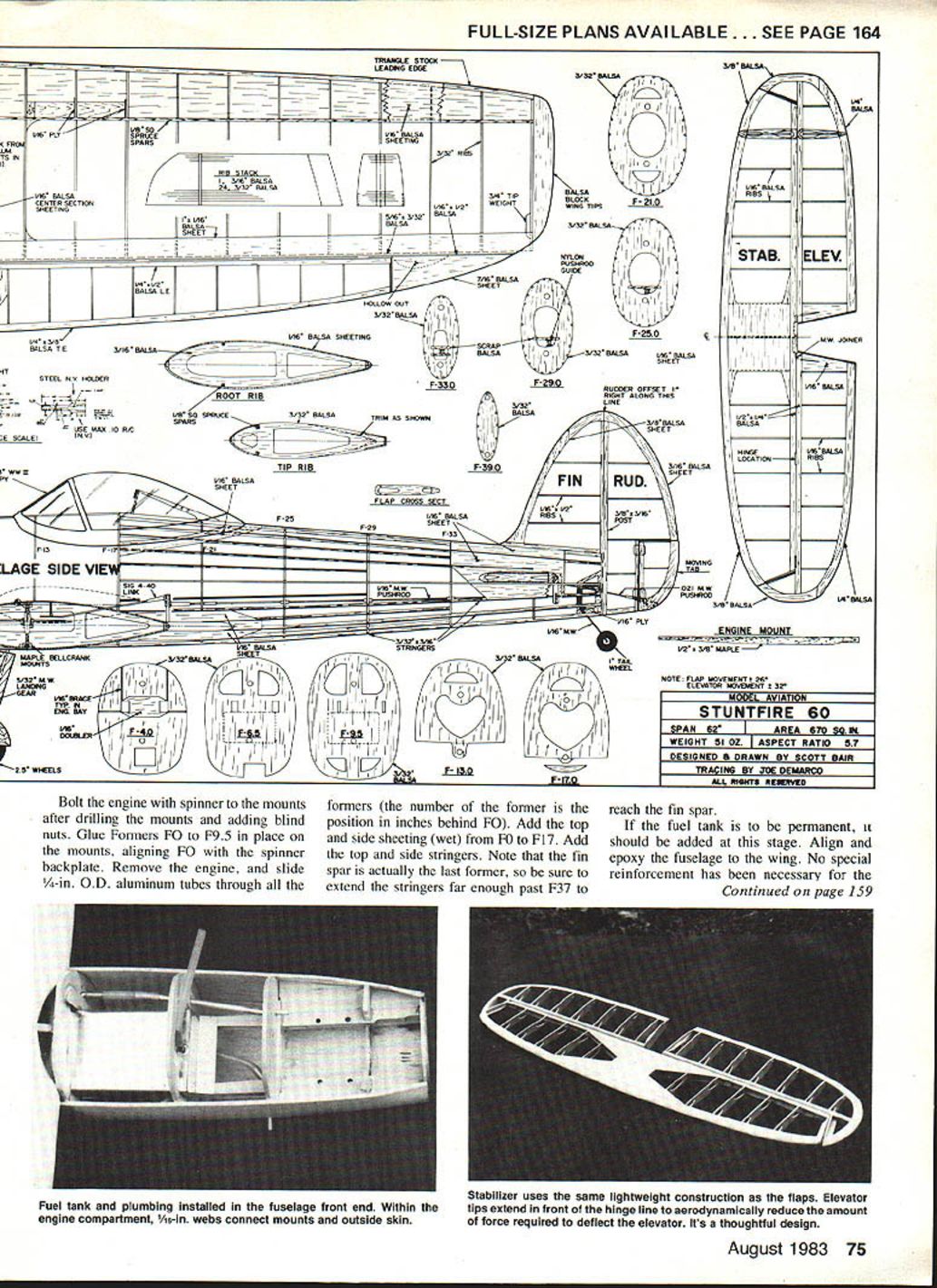
- Bolt the engine with spinner to the mounts after drilling the mounts and adding blind nuts.
- Glue formers F0 to F9.5 in place on the mounts, aligning F0 with the spinner backplate.
- Remove the engine and slide 1/4-in. O.D. aluminum tubes through all the formers (the former number is the position in inches behind F0).
- Add top and side sheeting (wet) from F0 to F17. Add top and side stringers. Note the fin spar is effectively the last former; extend the stringers far enough past F37 to reach the fin spar.
- If the fuel tank is permanent, install it now. Align and epoxy the fuselage to the wing. No special reinforcement has been necessary for the wing–fuselage joint; add 1/4-in. sheet flanges between the stringers at the canopy position and wing joint as shown on the plan.
- Build the fin and stabilizer and glue them to the fuselage. F37 must be cut as shown; add flanges at the fin and stabilizer.
- Install the pushrod and guides, build the cooling outlet, and sheet the bottom of the forward fuselage.
- Reinstall the engine and carve a cowling to fit. Shroud the engine cooling fins closely for best cooling and provide a cooling duct with minimal leakage to the rest of the compartment. Ventilation is provided by the scoop on the fuselage top.
- At this point the airplane should weigh about 15–18 oz. without engine and canopy.
- Final notes:
- Use maple beams cut to dihedral for the bellcrank mounting and mill a channel-shaped cross section to save weight.
- If using a spraybar/insert intake instead of the venturi shown, make the tank removable and use O-ring seals where appropriate.
Flying
- The airplane was designed around the ST 60BB engine. Provided the model is lightweight (about 51 oz.), it will perform best with a narrow 15-5 prop.
- Stuntfires tend to come out nose-heavy; add tail weight until the model turns easily. The small moment of inertia and large stabilizer volume produce a well-mannered turn.
- An operating rudder tab (shown on the plan) is helpful in correcting precession from the large prop but is not absolutely necessary.
- Trimming procedure:
- Fly the airplane with about 1/8 in. down elevator for level flight from your normal circle at about 40 ft.
- If it tries to climb, decrease wing incidence to lower the nose; if it tends to dive, increase incidence.
- Adjust right thrust with test flights as necessary—use small changes and allow one or two flights between adjustments.
Transcribed from original scans by AI. Minor OCR errors may remain.

