
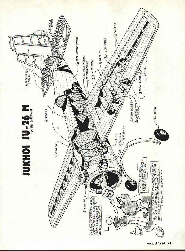
Sukhoi Su-26M
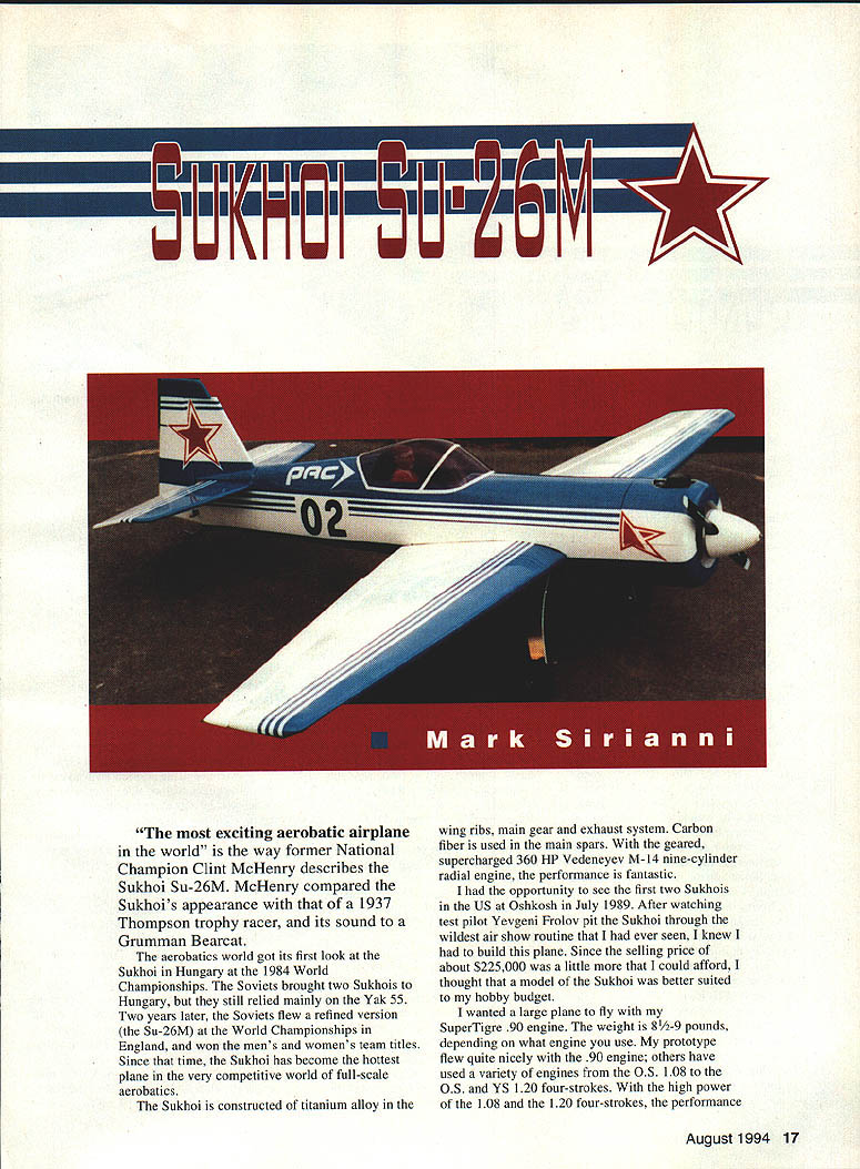
"The most exciting aerobatic airplane in the world" is the way former National Champion Clint McHenry describes the Sukhoi Su-26M. McHenry compared the Sukhoi's appearance with that of a 1937 Thompson Trophy racer and its sound to a Grumman Bearcat.
The aerobatic world got its first look at the Sukhoi in Hungary at the 1984 World Championships. The Soviets brought two Sukhois to Hungary, but they still relied mainly on the Yak-55. Two years later the Soviets flew a refined version (the Su-26M) at the World Championships in England and won the men's and women's team titles. Since that time the Sukhoi has become the hottest plane in the very competitive world of full-scale aerobatics.
The Sukhoi is constructed of titanium alloy in the wing ribs, main gear and exhaust system. Carbon fiber is used in the main spars. With the geared, supercharged 360-hp Vedeneyev M-14 nine-cylinder radial engine, the performance is fantastic.
I had the opportunity to see the first two Sukhois in the U.S. at Oshkosh in July 1989. After watching test pilot Yevgeni Frolov put the Sukhoi through the wildest air-show routine I had ever seen, I knew I had to build this plane. Since the selling price of about $225,000 was a little more than I could afford, I thought that a model of the Sukhoi was better suited to my hobby budget.
I wanted a large model to fly with my SuperTigre .90 engine. The model weight is about 8½ to 9 pounds, depending on what engine you use. My prototype flew quite nicely with the .90 engine; others have used a variety of engines. With the high power of the O.S. .108 and the O.S. and YS .120 four-strokes, the performance is outstanding. Whichever engine you choose, the Sukhoi will give you many hours of great flying.
CONSTRUCTION
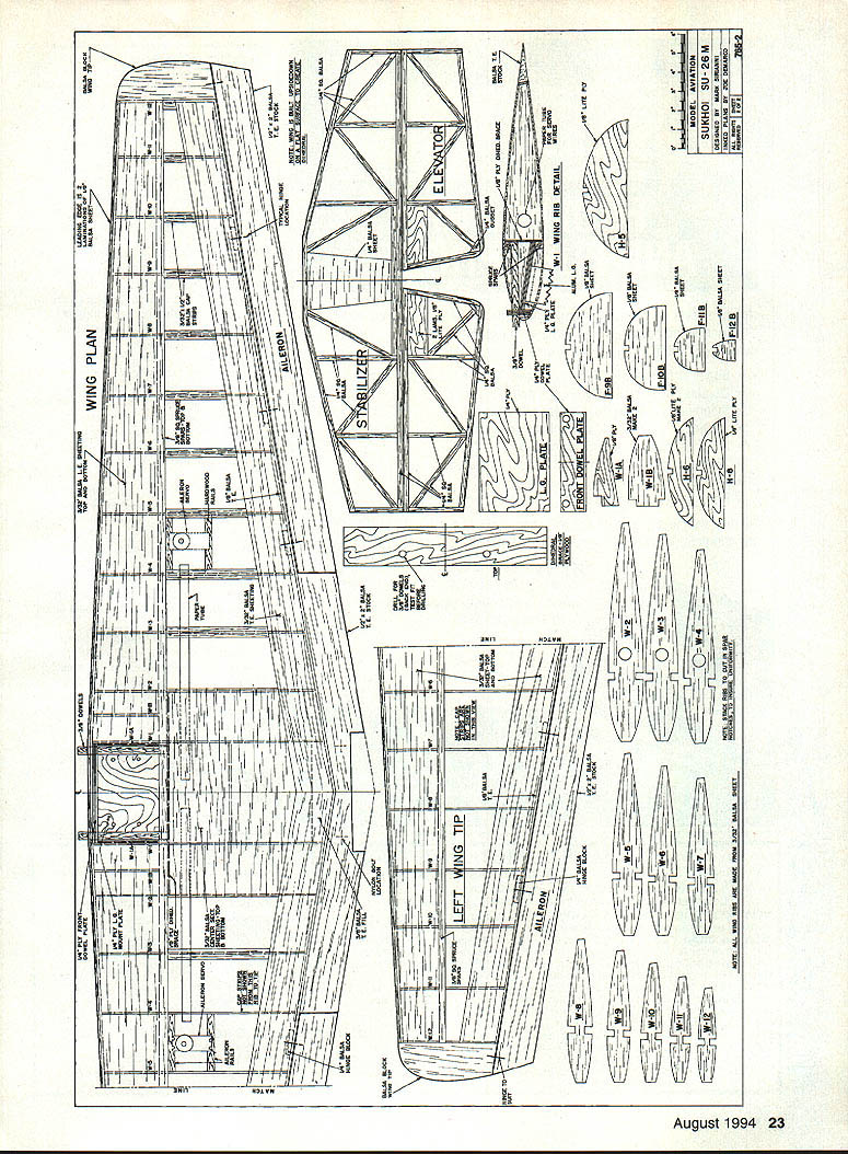
Wing
Pick a piece of hard 1/8" balsa and cut the jig. It's 36 inches long and tapers from 1/16" to 1/2".
- Pin the lower 3/8" square spruce spar to the plan. Pin the jig in place with the 1/4" end at rib 12. Pin the ribs in place and trim where necessary. Pin the ribs to the spar and jig and glue in place. Glue the top spar in place.
- Add the leading edge to the ribs. Glue the 1/8" x 3/8" strip to the trailing edge. Add 3/32" leading-edge sheeting from rib 1 outward. Do not sheet over the center area at this time. Add the 3/32" x 2" trailing-edge sheeting.
- Now build the other wing panel up to this point.
- Cut a 1/8" slot at the back edge of the spar on rib 1. This will allow the 1/8" plywood dihedral brace to slide through. Draw a 72-inch line on your workbench as a guide to align the wing panels when joining them.
- The wing halves are joined together upside down. Lay some waxed paper at the center and pin the panels with the main spars exactly on the line. Shim the center section 3/4" at the trailing edge and 1/4" at rib 12. Epoxy the dihedral brace securely in place on the back of the main spars. Glue the balsa filler at the trailing edge. Let the wing dry thoroughly.
- Epoxy the 1/8" plywood ribs 1A in place. These two ribs are flush with the top of wing rib 1. This rib sets the proper angle for the landing gear plate.
- Epoxy the landing gear plate in place. Take your time to get the plate securely into position—this is the most important part of the wing. All the stress of the landing gear is going to be on this plate, so do a good job.
- Drill two 3/8" holes in the front dowel plate. Epoxy in place, and add balsa ribs 1B and the 3/32" bottom leading-edge sheeting. When dry, cut the opening for the landing gear. Install the landing gear with four 6-32 screws and blind nuts.
- Add the bottom trailing-edge sheeting. Sheet the top center section only; the bottom will be finished after the wing is fitted to the fuselage.
- Attach the 1/2" x 2" trailing edge, the aileron servos, and paper tubes for servo wires. Add cap strips and wingtips.
- Sand the wing and set aside. You will need the completed wing to construct the fuselage.
Tail
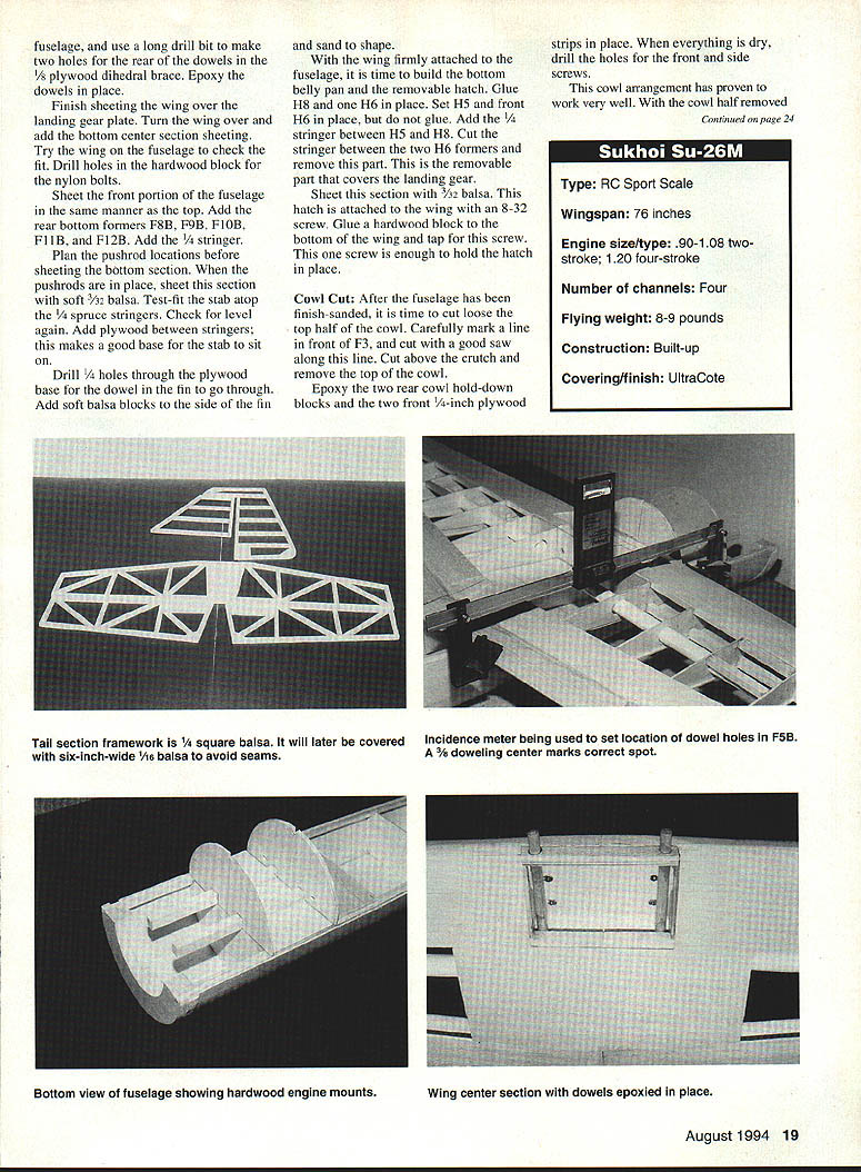
The tail pieces are constructed from 1/4" square balsa and then sheeted with 1/16" balsa. Build the stabilizer, elevators, fin and rudder over the plans. I used six-inch-wide 1/16" balsa for the sheeting (using wider stock eliminates seams). Sand the pieces and set aside until later.
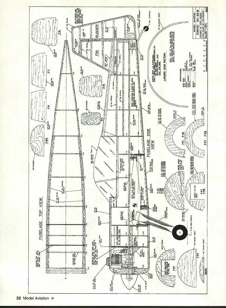
Fuselage
The fuselage is built in top and bottom halves on a 1/4" square crutch. The 1/4" square is pinned to your flat building board and the top-half fuselage formers are glued to it. Pin a spruce doubler over the top-view plans. Add two 1/2" balsa formers. Glue F2 to the back of F1. Use the engine to determine how far back you should position F3. The plans show the approximate position for a 1.20 four-stroke engine. Your engine must be mounted upright on the hardwood rails. Attach F4, F5 and F6, and build the tank compartment. Add a top stringer between F2 and F6. Drill holes for the throttle pushrod; remaining top formers and spruce stringers between F9 and F11 are now glued in place. Make sure the top stringer is parallel to your work surface, because the stabilizer sits on these stringers.
Add the balsa tail posts and the cockpit floor on top of F6, F7 and F8.
After this basic framework is dry, sheet the top half of the fuselage. Using soft 3/32" x 4" balsa, carefully sheet the fuselage. Make sure the framework remains securely pinned to your workbench. I use aliphatic resin glue here; it gives you plenty of time to pin the balsa sheeting to all the top formers.
Lightly sand the tops of F9, F10 and F11. Add the balsa top, cutting this piece a little oversize to allow for final sanding. After the top is dry, remove the assembly from the building board, turn the body over and prepare to build the bottom half.
Use the engine to carefully measure spacing needed for the hardwood mounts. Cut notches into bottom formers F3B and F5B. Take your time in the next few steps to get the mounts straight, with no side or down thrust. When you are sure everything is straight, epoxy the mounts in place. For the next steps you need the completed wing. Take your time to properly align the wing and drill the dowel holes in F5B.
With the fuselage upside down on your workbench, use a level to align the fuselage with the top of your workbench. If you have an incidence meter this step is easier. Put the wing in place on the fuselage. To mark the dowel locations on F5B, use a doweling center. The 3/8" doweling center is a metal plug with a sharp point on one end. The plug fits into the 3/8" hole in the 1/4" plywood front dowel plate. Simply set the wing in the saddle area and, at 0° incidence, press forward. The doweling center will put a small mark on F5B at the exact location for the holes. Drill the two holes in F5B. Remove the wing from the fuselage and use a long drill bit to make two holes for the rear of the dowels in the 1/8" plywood dihedral brace. Epoxy the dowels in place.
Finish sheeting the wing over the landing gear plate. Turn the wing over and add the bottom center-section sheeting. Try the wing on the fuselage to check fit. Drill holes in the hardwood block for the nylon bolts.
Sheet the front portion of the fuselage in the same manner as the top. Add the rear bottom formers F8B, F9B, F10B, F11B and F12B. Add 1/4" stringers.
Plan the pushrod locations before sheeting the bottom section. When the pushrods are in place, sheet this section with soft 3/32" balsa. Test-fit the stabilizer atop the 1/4" spruce stringers. Check for level again. Add plywood between stringers; this makes a good base for the stabilizer to sit on.
Drill 1/4" holes through the plywood base for the dowel in the fin to go through. Add soft balsa blocks to the sides of the fin and sand to shape.
With the wing firmly attached to the fuselage, build the bottom belly pan and the removable hatch. Glue H8 and one H6 in place. Set H5 and the front H6 in place but do not glue. Add the 1/4" stringer between H5 and H8. Cut the stringer between the two H6 formers and remove this part. This is the removable section that covers the landing gear.
Sheet this section with 3/32" balsa. This hatch is attached to the wing with an 8-32 screw. Glue a hardwood block to the bottom of the wing and tap for this screw. One screw is enough to hold the hatch in place.
Cowl cut: After the fuselage has been finish-sanded, it is time to cut loose the top half of the cowl. Carefully mark a line in front of F3, and cut with a good saw along this line. Cut above the crutch and remove the top of the cowl.
Epoxy the two rear cowl hold-down blocks and the two front 1/4" plywood strips in place. When everything is dry, drill the holes for the front and side screws. This cowl arrangement has proven to work very well.
Illustrations (captions)
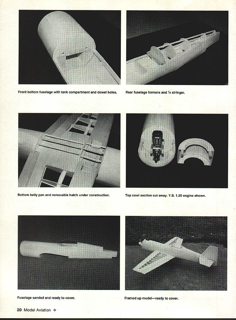
- Front bottom fuselage with tank compartment and dowel holes.
- Rear fuselage formers and 1/4" stringer.
- Bottom belly pan and removable hatch under construction.
- Top cowl section cut away. Y.S. 1.20 engine shown.
- Fuselage sanded and ready to cover.
- Framed-up model—ready to cover.
Transcribed from original scans by AI. Minor OCR errors may remain.

