

Sundancer
Joseph M. Nunes
This 1/2A control-line ship can be built quickly and inexpensively. And it pays big dividends in pleasurable flying.
While listening to the radio I heard the weatherman call for a nice, sunny weekend — perfect for model flying. The more I thought about going to the flying field, the more I remembered the great times spent while learning to fly various control-line stunts. "Why not," I said to myself, "this weekend the RC gear will have to stay home 'cause this boy's going round and round!" Whoops — there wasn't a control-line plane or kit to be found anywhere in my workshop. Actually, this small enigma turned out to be a blessing in disguise. I took the opportunity to design and assemble a 1/2A sport plane that just about "flew the socks off" me. Talk about fun!
The Sundancer is made to fly, and it does this very well. After the first flight, my helper and good friend Jim Jones of Horton, MI, and I just stood looking at each other. Was it really going that fast? After the second flight I calculated that this ship was flying about 59.97 mph in level flight. Brother, that's "smokin" on 35-ft lines. This plane is exhilarating. It has good pull on the lines, and it tracks real nice. Stunts are fast and fun! It was a great payoff in enjoyment for a few dollars' worth of balsa and ply and about eight hours total in design and construction time, start to finish.
Indeed, as you look over the plans and photos, you'll note that the aircraft is quite easy to build. Simplicity can be very effective when used properly. My design criterion: If it ain't needed, it ain't there. You will find that this boils down to fast, economical construction which results in more flying time. Construction is straightforward. With newcomers in mind, building instructions follow. There are a few other points worthy of mention, however, and these will be given first.
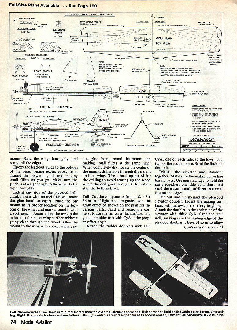
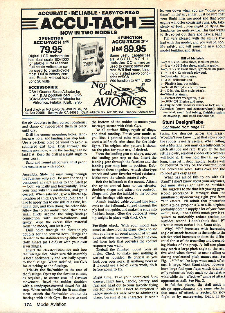
The Sundancer was designed for a Cox Tee Dee .051 which I had left over from my earlier free-flight days. The power from this little gem is quite impressive. I would highly recommend that you consider a Cox Tee Dee, as shown on the plans, as the engine for your model. Should you want to use a conventional .049 with attached fuel tank, you can easily modify the front end of the model to suit your particular engine. The overall speed will be down without the Tee Dee engine, but the model's maneuverability will still be great.
Small rubber bands are used to secure the fuel tank to the fuselage and for securing the landing gear to the landing-gear stop. This kind of mounting is quick and simple, and it provides a bit of shock resistance for those times when landings are a bit less than ideal.
Build lightly. Sand off all excessive weight from the model. Sand all edges, especially on the wing. Go easy on use of epoxy, and be sure to wipe all excess glue from the model.
Construction
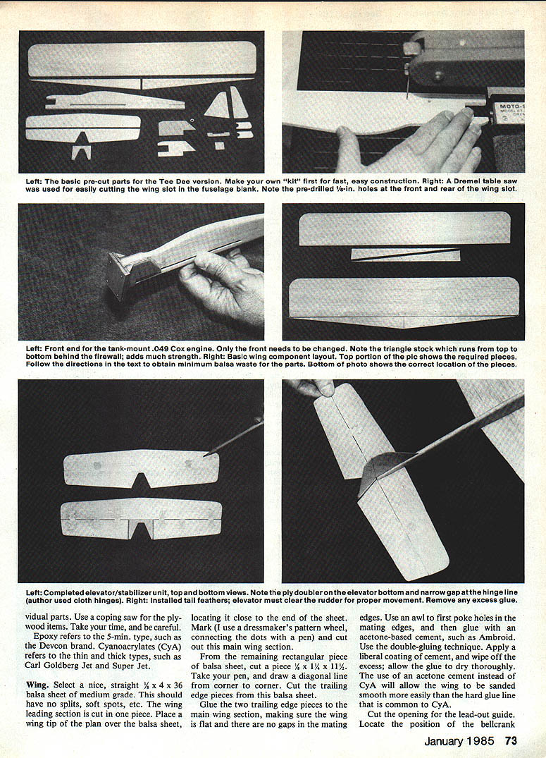
Build the model on a flat working surface. Cut out the parts with a small tabletop hobby saw, such as the one made by Dremel. This will really speed up the cutting chores, especially for the plywood parts. If you do not have such a saw, use a steel straightedge and a sharp hobby knife for the balsa parts. Try to make several light cuts instead of one heavy cut when you are cutting the individual parts. Use a coping saw for plywood items. Take time and be careful.
"Epoxy" refers to 5-minute type such as Devcon. Cyanoacrylates (CyA) refers to thin and thick types such as Carl Goldberg Jet Super Glue.
Wing
- Select a nice, straight 1/4 x 4 x 36 in. balsa sheet of medium grade. This should have no splits, soft spots, etc.
- The wing leading section is cut in one piece. Place a wing tip of the plan over the balsa sheet, locating it close to the end of the sheet. Mark (I use a dressmaker's pattern wheel, connecting the dots with a pen) and cut out this main wing section.
- From the remaining rectangular piece of balsa sheet, cut a piece 1/2 x 1 1/4 x 11 1/2 in. Take your pen and draw a diagonal line from corner to corner. Cut the trailing-edge pieces from this balsa sheet.
- Glue the two trailing-edge pieces to the main wing section, making sure the wing is flat and there are no gaps in the mating edges. Use an awl to first poke holes in the mating edges, and then glue with an acetone-based cement, such as Ambroid. Use the double-gluing technique: apply a liberal coating of cement and wipe off the excess; allow the glue to dry thoroughly. The use of an acetone cement instead of CyA will allow the wing to be sanded smooth more easily than the hard glue line common to CyA.
- Cut the opening for the lead-out guide. Locate the position of the bellcrank.
- Sand the wing thoroughly, and round all the edges.
- Epoxy the lead-out guide to the bottom of the wing, wiping excess epoxy from around the plywood guide and making small fillets as you go. Make sure the guide is at a right angle to the wing. Let it dry thoroughly.
- Indent one side of the plywood bellcrank mount with an awl (this will make the glue bond stronger). Place the ply mount at its proper location on the bottom of the wing, and mark around it with a soft pencil. Again using the awl, poke holes into the balsa wing surface without going clear through the wood. Glue the mount to the wing with epoxy, wiping excess glue from around the mount and making small fillets at the same time.
- When completely dry, locate the center of the mount; drill a hole through the mount and the wing. (Use a back-up board for the drilling to avoid tearing up the wood where the drill goes through.) Do not install the bellcrank yet.
Tail
- Cut the components from a 1/16 x 3 x 36 in. balsa sheet of light-medium grade. Note the grain direction shown on the plan for the various parts. Sand and round the corners.
- Place the fin on a flat surface, and glue the rudder to it with CyA at the proper offset angle.
- Attach the rudder doublers with thin CyA, one on each side, to the lower bottom of the rudder piece. Sand the fin/rudder unit.
- Trial-fit the elevator and stabilizer together. Make sure the mating hinge line has no gaps. Use masking tape to hold the parts together, one side at a time, and sand the elevator and stabilizer as a unit. Round the edges.
- Cut out and finish-sand the plywood elevator doubler. Indent the mating surface with an awl, preparatory to gluing. Attach the doubler to the underside of the elevator with thick CyA. Sand the unit well, making sure the leading edge of the plywood doubler is beveled so as to allow the elevator to function properly when attached to the fuselage.
Fuselage
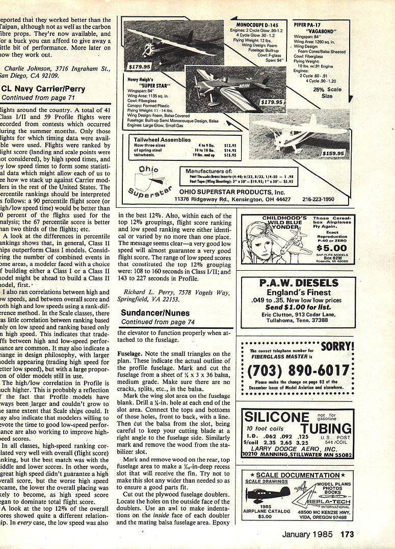
- Note the small triangles on the plan. These indicate the actual outline of the profile fuselage. Mark and cut the fuselage from a sheet of 1/4 x 3 x 36 in. balsa, medium grade. Make sure there are no cracks, splits, etc., in the balsa.
- Mark the wing-slot area on the fuselage blank. Drill a 1/8-in. hole at each end of the slot area. Connect the tops and bottoms of those holes, front to back, with a line. Then cut the balsa from the slot, being careful to keep your cutting blade at a right angle to the fuselage side. Similarly, mark and remove the wood from the stabilizer slot.
- Mark and remove wood on the rear, top fuselage area to make a 1/16-in.-deep recess that will receive the fin. Try not to make this slot any wider than needed so as to ensure a good parts fit.
- Cut out the plywood fuselage doublers. Locate the holes on the outside face of the doublers. Use an awl to make indentations on the inside face of each doubler and the mating balsa fuselage area. Epoxy the doublers to the fuselage, being sure to align them properly. Remove any excess glue and sand smooth.
- Cut the opening for the lead-out guide and locate the position of the bellcrank. Drill the holes required for any mounts or dowels and fit the bellcrank assembly into the fuselage, but do not install the control linkage at this time. Trial-fit the engine mount and make any necessary modifications for the engine you plan to use.
- Install the landing gear by locating and gluing the gear mounts into the fuselage. Use small hardwood dowels or triangle stock as shown on the plan to reinforce the firewall area. Make sure the gear is square with the fuselage and provides adequate shock resistance for landings.
- Fit the wing to the fuselage and check for proper incidence and dihedral. When satisfied with the fit, glue the wing in place and securely fillet the joints with epoxy or an appropriate cement. Install the tail feathers and check that the elevator clears the rudder through the full range of motion.
Final sanding and finishing
- Fill any low spots with lightweight filler, sand all surfaces smooth, and seal the model with a thin coat of dope or a light sanding sealer before covering.
- Balance the model at the location shown on the plan by adding weight to the nose or tail as required. Make sure the aircraft is properly balanced and that all control surfaces move freely and correctly before attempting the first flight.
Flight time
Take your completed Sundancer, flight lines, handle, battery, and fuel and head out to your favorite flying site for some fun. Don't be surprised if fellow modelers walk over to admire this plane, because it has character. It won't let you down when you are "doing your thing" in the air, either. Just be sure that your flight lines are good and that your engine will offer consistent runs. Oh — take plenty of fuel... you might be flying the Sundancer for quite a while. This bird wants to fly, so get out there and have a ball!
I'm very pleased with the results I've had with this model, and you will be, too. Fly safely, and tell someone new about model building and flying.
Bill of Materials
- 1 — 1/4 x 3 x 36 in. balsa sheet, medium grade (fuselage)
- 1 — 1/4 x 4 x 36 in. balsa sheet, medium grade (wing)
- 1 — 1/16 x 3 x 36 in. balsa sheet, light/medium grade (tail)
- 1 — 1/8 x 2 x 12 in. aircraft plywood
- 1 — 1/16-in. dia. music wire (for landing gear and fittings)
- 1 — 2-in. bellcrank unit
- 1 — Flexible lead-out cables
- 1 — Small nylon control horn
- 2 — 1/8-in. dia. slim-style wheels
- Wheel retainers
- 1 — Perfect #19 wigetank, 1/4 oz.
- 1 — .049/.051 engine and prop (Cox Tee Dee .051 recommended)
- 4 — Engine bolts with lockwashers or locking units
- Adhesives (epoxy and cyanoacrylates), hinge material, small fuel tubing, finishing paints or coverings, and small rubber bands
Transcribed from original scans by AI. Minor OCR errors may remain.

