
Super Akro-1 "Chips"
By Brad Shepherd
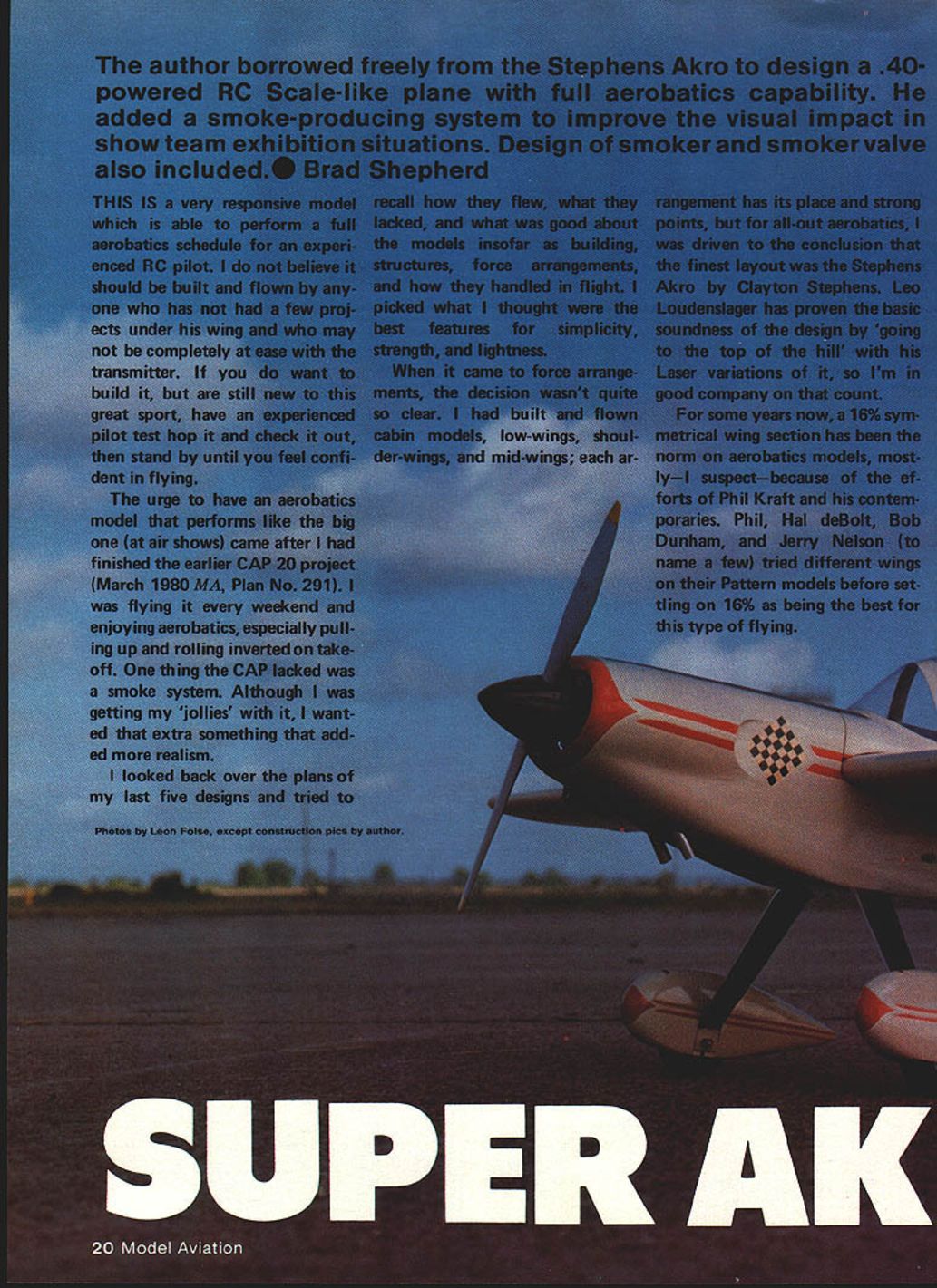
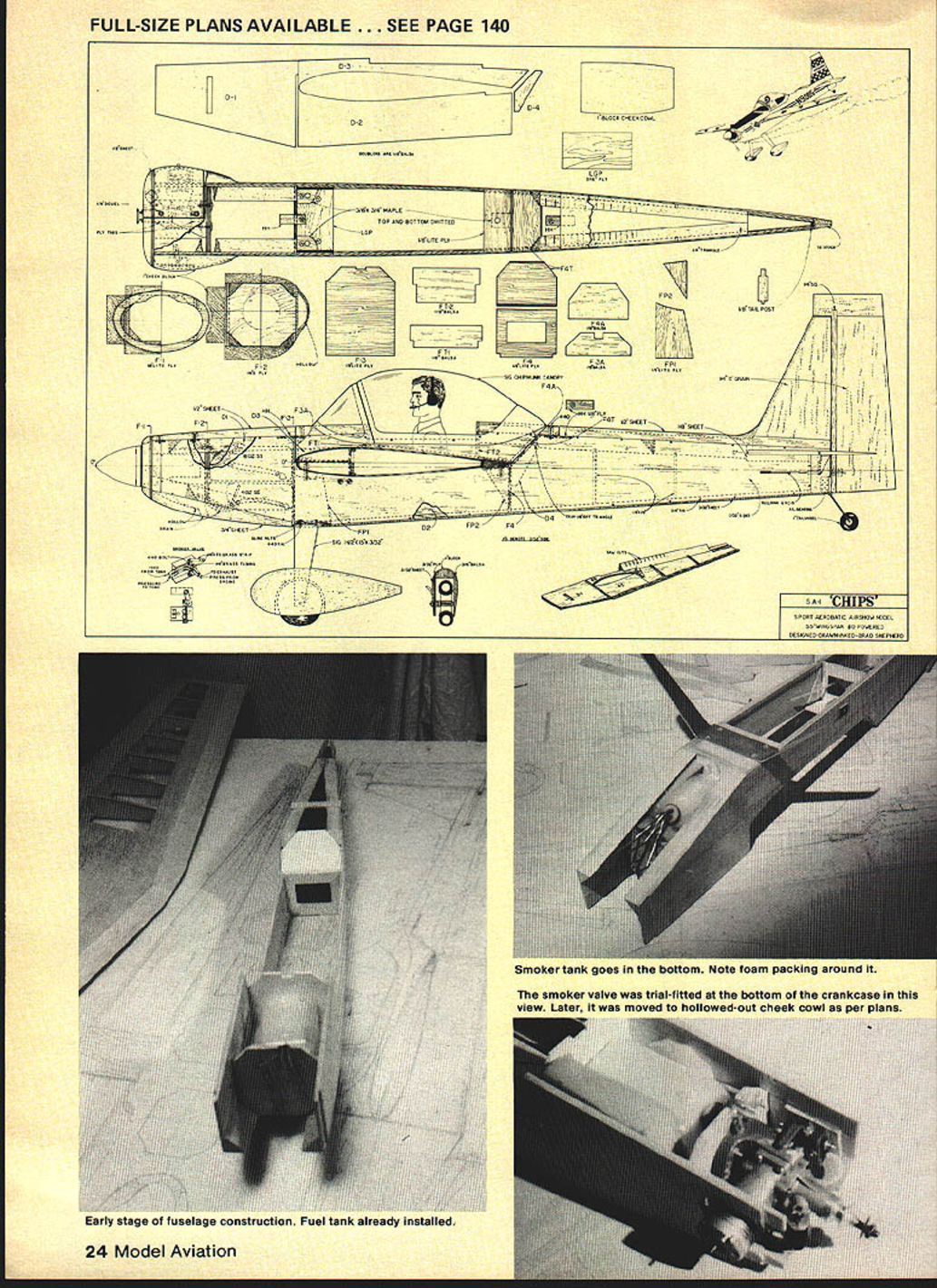
This .40-powered RC scale-like Akro is a compact, full-aerobatic model inspired by the Stephens Akro. I borrowed the best features from previous designs for simplicity, strength and lightness, and added a smoke system to give better visual impact in show-team exhibition work. The smoker and a simple, reliable smoker valve design are included in the plans.
Overview and pilot note
This is a very responsive model capable of a full aerobatics schedule for an experienced RC pilot. It is not recommended for a novice who is not comfortable on the transmitter. If you are new but want to build it, have an experienced pilot test-hop it and stand by until you are confident.
Design choices
- Airframe influenced by the Stephens Akro (Clayton Stephens); layout proven by full-scale and Laser variations.
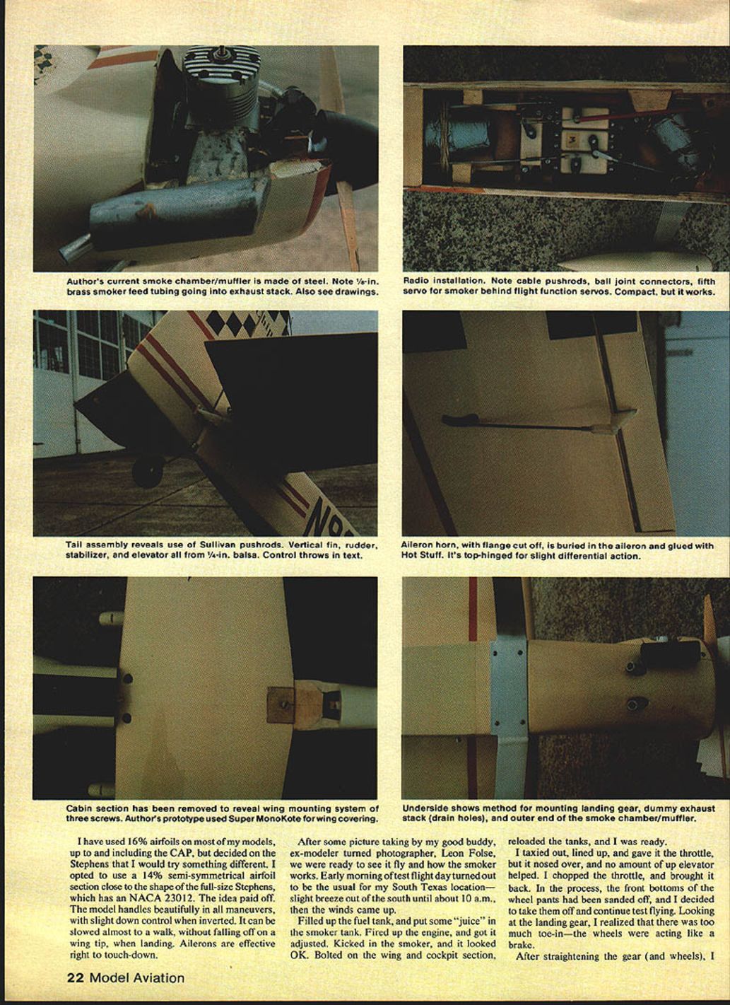
- Airfoil: 14% semi-symmetrical section, close to the full-size Stephens (NACA 23012). I chose 14% rather than the more common 16% used on many pattern ships; the result is excellent handling with slight down control when inverted and effective ailerons right to touchdown.
- Power: .40-class engine. Running a .40 with a smoker presents challenges because of lower exhaust heat compared with .60+ engines; the muffler/smoke chamber is designed to compensate.
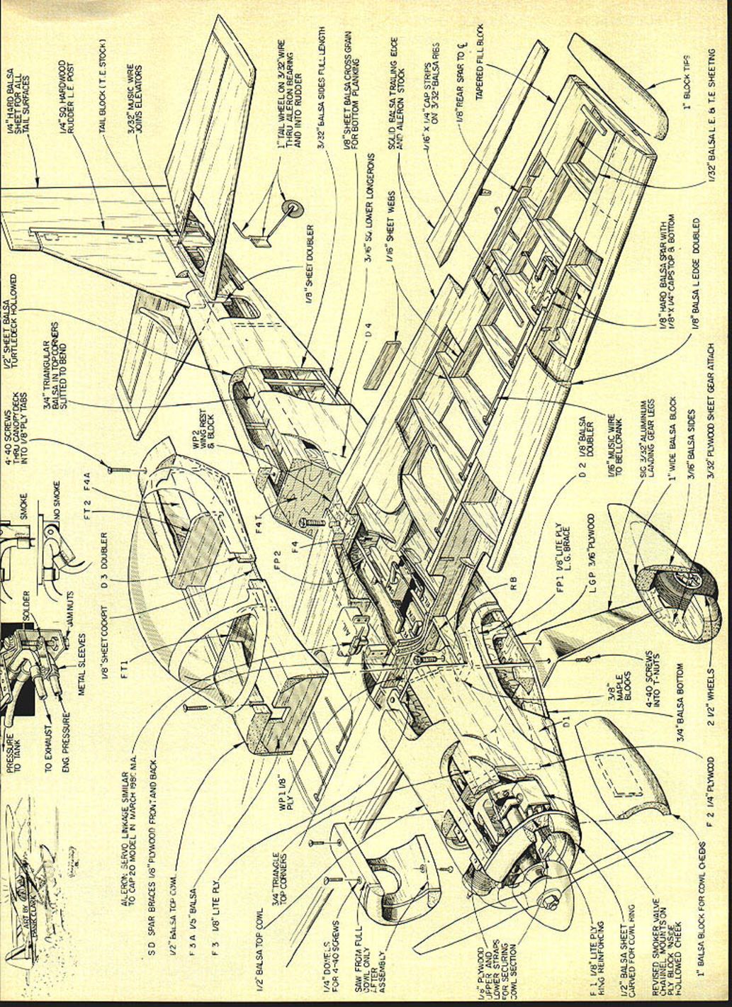
- Smoker system: steel smoke chamber/muffler with 1/16-in. brass feed tubing to the exhaust stack. A custom smoker valve pinches silicone tubing for positive shutoff with no servo load; valve can be located in hollowed cheek cowl as shown on the plans.
Flight testing and handling
- Ground testing: fill fuel and smoker tanks, set engine and smoker, bolt wing/cabin on and go.
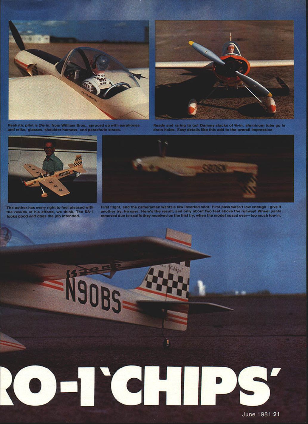
- Early test hop encountered excessive landing-gear toe-in (wheels acting as brakes); straighten gear before further flights.
- Handling: straight and steady. Requires some up trim initially until engine settings are adjusted.
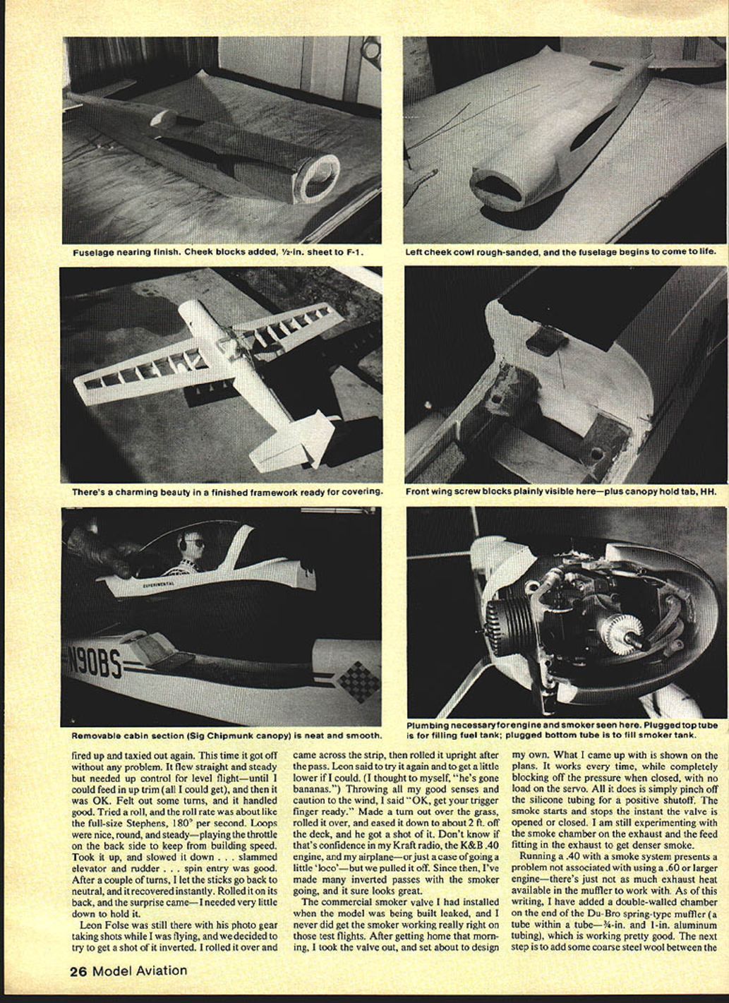
- Aerobatics: roll rate similar to full-size Stephens (about 180°/sec). Loops are round and steady; snap rolls good at half throttle; spins enter well and recover promptly when sticks are released. Inverted flight needs very little down elevator to hold.
- Landing: typical tail-dragger technique—keep a little power on final, chop power about 2 ft off the deck for a nice three-point "kiss the tarmac" landing.
- Visual shows: inverted passes with smoker on are highly effective; smoker starts/stops instantly with the pinch-type valve.
Smoker system and valve
- Problem with commercial valve leaking led to a home-designed valve: a simple pinch valve that compresses silicone tubing to fully block pressure when closed. It requires no continuous servo load and provides instant on/off smoke control.
- Smoker tank is installed low in the fuselage (bottom) with foam packing around it. Valve pushrod tubing is routed along the left side of the fuel tank.
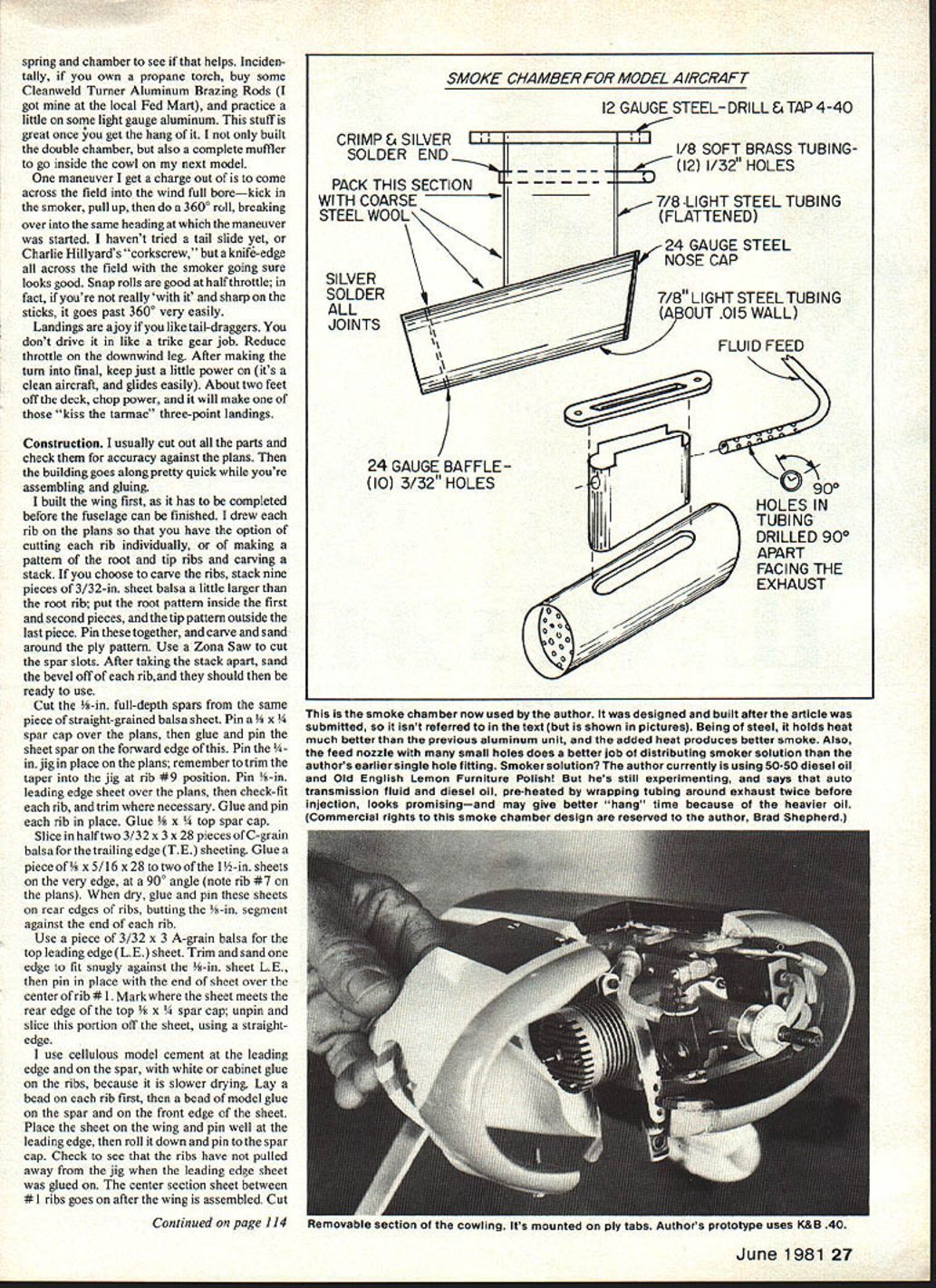
- Muffler/smoke chamber: steel construction. I added a Du-Bro spring-type muffler (tube-within-a-tube and 1-in. aluminum tubing) to work with the smaller .40 exhaust heat.
- Further experiments: adding coarse steel wool between spring and chamber to trap and heat oil more effectively.
- Fabrication tip: practice brazing light-gauge aluminum with Cleanweld Turner aluminum brazing rods and a propane torch.
Construction
General
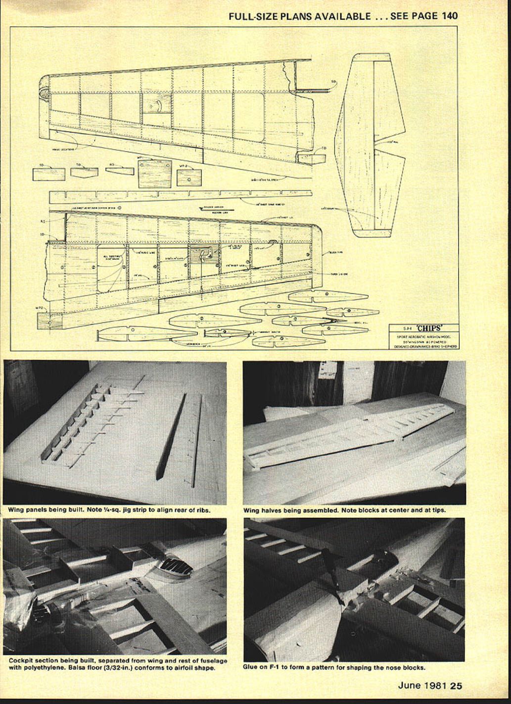
I usually cut all parts and check accuracy against the plans before gluing. Build the wing first; the fuselage is finished around the completed wing. The plans give full-size parts and detail; the following highlights construction steps and techniques used on my prototype.
Wing
- Ribs: Draw each rib on the plans so you can cut individually or make patterns. To carve a stack, stack nine pieces of 3/32-in. sheet balsa slightly larger than the root rib, pin with ply patterns and carve/sand around the pattern. Use a Zona Saw for spar slots.
- Spars: Cut 1/8-in. full-depth spars from straight-grained balsa. Pin a 1/4 x 1/4 spar cap over the plans, glue and pin the 1/8-in. sheet spar on the forward edge. Pin the 1/8-in. jig and remember to trim taper at rib #9 position.
- Leading edge and sheeting: Pin 1/8-in. leading-edge sheet over the plans, fit each rib, glue and pin ribs in place. Glue 1/8 x 1/4 top spar cap. Slice two 3/32 x 3 A-grain sheets for trailing-edge sheeting; glue and fit rear sheeting as shown.
- Sheeting technique: Use cellulose model cement at the leading edge and spar and white or cabinet glue on ribs (slower drying). Lay beads on ribs and spar caps, position sheet and pin. Add 1/16-in. sheet webs between ribs and trailing-edge sheeting for stiffness.
- Center section: Epoxy WP-1 to the ply RDs and SD ply doubler. Sheet the top center behind the spar; leave the leading-edge center section until later. After sheeting, sand with a long block (220 grit).
- Trailing-edge center: Pin panels upside down, trial-fit 3 x 1-1/4 trailing-edge piece and glue in place. Do not sand out the slight reflex toward the tips; smooth the joint transition only.
- Final shaping: Glue the 1/4-in. forward L.E. piece, glue and shape tip blocks around rib #9, round front and sand with 100-grit. Epoxy WP-2 after T.E. is straight. Final sand with 220-grit.
Fuselage
- Sides: Lay out fuselage sides on 3/32 x 6 x 36 balsa; draw thrust line and parallel wing center and stabilizer center lines. Cut side panels and use first side as pattern for the mate.
- Cuts and formers: Make top cuts behind F-3 and between F-4-A and F-4-T as shown on plans. Glue 3/16-in. bottom longerons and doublers D-2, D-3, etc.
- Stabilizer slot: Lay out and cut 1/4-in. stabilizer slot and glue 1/4-in. reinforcement and 1/8 x 1/4 stiffeners.
- Firewall and engine mount: Lay out engine bolt holes on F-2, drill and install bolts. Solder short pieces of music wire across bolt heads and epoxy behind the firewall. Paint or epoxy inside engine compartment for fuel-proofing later.
- Assembly: Pin sides over top view, slip in formers F-3 and F-4 for squareness. Glue tail post and top triangle with 5-minute epoxy; install F-4, F-3, F-2, and F-4-T in sequence.
- Landing gear: Install landing gear plate and blind nuts; smear a little epoxy to secure. Note landing-gear mounting method and 4-40 screws on plans.
- Tanks and smoker: Install fuel and smoker tanks (packed in foam). Suggest using a Sullivan RST tank for the smoker. Install smoker-valve pushrod tubing on the left side of the fuel tank and throttle pushrod tubing.
- Wing saddle and alignment: Fit wing in saddle using center lines, pin and measure wingtip-to-tailpost distances to square. Drill mounting holes for 1/4-20 nylon screws and tap holes. Trial-fit stabilizer and glue parallel and square.
- Cabin and removable cockpit: Pin and glue cabin sides, glue 3/32-in. sheet inside over wing area, install FT formers. Glue blocks front and back of cabin, F-1, and carve blocks to rough shape. Mount cabin with dowel pins and 4-40 flat-head bolts into blind nuts as shown.
- Cheek cowl and cowl hold tabs: Glue cheek blocks, carve to shape, hollow inside cheeks to about 3/16-in. thickness, and shape air outlets and drain holes. Trial-fit cowl and install cowl hold-tabs with dowels and blind nuts.
- Final shaping: Sand the fuselage to rough shape, hollow area behind cabin where noted, and glue permanently. Paint engine compartment inside with slow-drying epoxy after covering engine bolts with fuel tubing.
- Canopy and pilot: Fit canopy, paint cabin interior flat black (talcum added to black dope), make a pilot from a 2-5/8-in. William Bros. figure mounted on a 1-in. balsa block, paint and fit under canopy. Use masking tape and Hot Stuff glue to attach canopy—mask before finishing.
Radio and control installation
- Radio layout: Cable pushrods, ball-joint connectors and a fifth servo for smoker control behind flight-function servos. A compact installation works well.
- Ailerons: Lay out ailerons and cut with top-edge hinge slots for slight differential. Remove aileron horn flange, bury horn and glue to aileron with Hot Stuff. Install 1/16-in. music-wire pushrods, bend links and solder washer on dogleg as shown. Use Du-Bro dual connector to tie two pushrods together if needed.
- Tailwheel: Make tailwheel assembly with an aileron-horn bearing, insert 3/32-in. brass tubing in bearing, pass 1/16-in. music wire with a wheel collar, bend to shape. Mark and drill rudder for wire insertion, epoxy nylon tubing in hole.
- Control throws: Keep throws conservative for test flying. Elevator measured at the widest point: 1/2-in. up and 1/2-in. down (as a starting point).
Finishing and covering
- Wing covering: I used Super MonoKote on the wing. Set the iron temperature low—just enough heat to stick the MonoKote to MonoKote; practice on scraps.
- Fuselage finish: Sand smooth, apply light silkspan over balsa, dope coats (clear) and sand with 220-grit. Apply balsa filler-coat, sand and inspect by holding up to a light; repeat until smooth.
- Color match: I matched cream MonoKote by tinting white dope with small amounts of yellow, red and black to reach the proper shade.
- Masking: Mask canopy before finishing.
Flying tips and maneuvers
- Typical maneuvers: knife-edge across the field with smoker on, 360° roll starting up into the wind, snap rolls at half-throttle (needs precise stick timing), slow approaches and three-point landings for tail-dragger feel.
- Spins: Good spin entry; recovery is quick when sticks are returned to neutral.
- Be conservative on control throws during first flights and refine once trim is established.
Materials, hardware and notes
- Airfoil: 14% semi-symmetrical (close to NACA 23012)
- Spars, ribs and sheeting: 1/8-in. sheet spars, 3/32-in. rib stock, trailing-edge sheeting of 3/32-in. A-grain balsa
- Wing and fuselage blocks and doublers: assorted 1/4-in., 1/2-in., 3/32-in. and 1/8-in. balsa as noted on plans
- Ply: 1/8-in. plywood front and back and ply plates for radio and wing hold-downs
- Music wire: 1/16-in. and 3/32-in. for controls and tailwheel
- Landing gear: 4-40 screws and gear attach hardware; 3/32 plywood sheet gear attach
- Smoker: smoker tank, silicone feed tubing, 1/16-in. brass feed tubing, steel smoke chamber/muffler, Du-Bro spring-type muffler, 1-in. aluminum tubing, possible coarse steel wool filler
- Fasteners: 4-40 blind nuts and screws for cowl and cabin, 1/4-20 nylon wing hold-down screws
- Misc: epoxy (5-min and general), white or cabinet glue, cellulose cement, Hot Stuff CA, Super MonoKote, silkspan, dope and filler-coat
(See the full-size plans for exact stock sizes, exact plywood doublers and all part references.)
FULL-SIZE PLANS AVAILABLE. SEE PAGE 140.
Transcribed from original scans by AI. Minor OCR errors may remain.

