
Super Brigadier
Dee B. Mathews
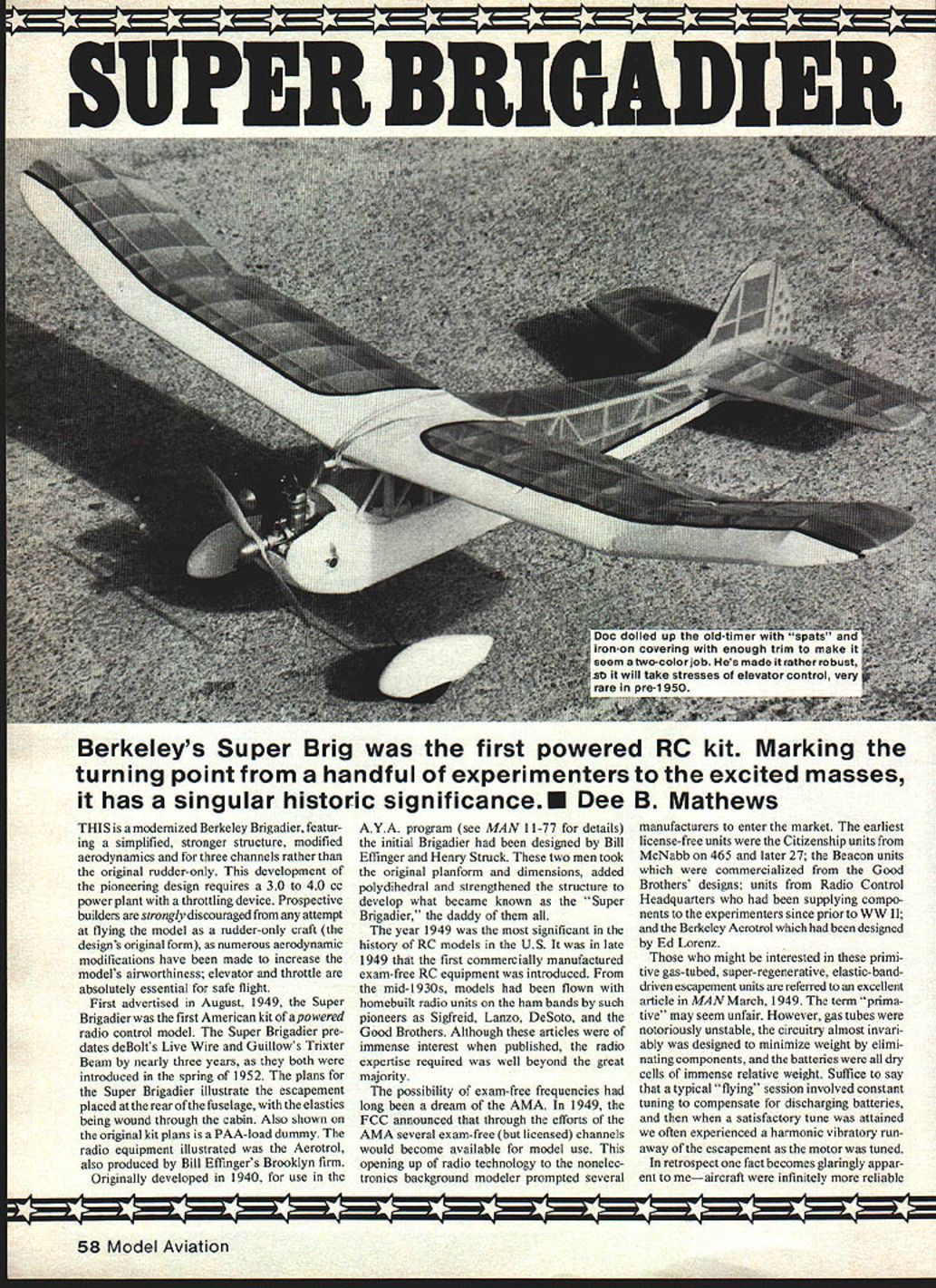
Berkeley's Super Brigadier was the first powered radio-control kit. Marking the turning point from a handful of experimenters to the excited masses, it has a singular historic significance.
This is a modernized Berkeley Brigadier, featuring a simplified, stronger structure, modified aerodynamics and provision for three channels rather than the original rudder-only. This development of the pioneering design requires a 3.0 to 4.0 cc power plant with a throttling device. Prospective builders are strongly discouraged from any attempt at flying the model as a rudder-only craft (the design's original form), as numerous aerodynamic modifications have been made to increase the model's airworthiness; elevator and throttle are absolutely essential for safe flight.
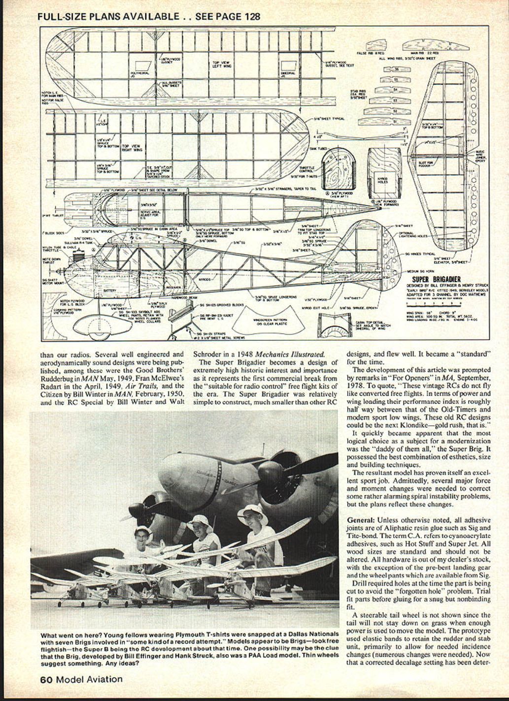
First advertised in August 1949, the Super Brigadier was the first American kit of a powered radio control model. The Super Brigadier predates deBolt's Live Wire and Guillows' Trixter Beam by nearly three years, as they both were introduced in the spring of 1952. The plans for the Super Brigadier illustrate the escapement placed at the rear of the fuselage, with the elastics being wound through the cabin. Also shown on the original kit plans is a PAA-load dummy. The radio equipment illustrated was the Aerotrol, also produced by Bill Effinger's Brooklyn firm.
Originally developed in 1940 for use in the A.Y.A. program (see MAN 11-77 for details), the initial Brigadier had been designed by Bill Effinger and Henry Struck. These two men took the original planform and dimensions, added polyhedral and strengthened the structure to develop what became known as the "Super Brigadier," the daddy of them all.
The year 1949 was the most significant in the history of RC models in the U.S. It was in late 1949 that the first commercially manufactured exam-free RC equipment was introduced. From the mid-1930s, models had been flown with homebuilt radio units on the ham bands by such pioneers as Siegfried Lanz, DeSoto, and the Good Brothers. Although these articles were of immense interest when published, the radio expertise required was well beyond the great majority.
The possibility of exam-free frequencies had long been a dream of the AMA. In 1949, the FCC announced that through the efforts of the AMA several exam-free (but licensed) channels would become available for model use. This opening up of radio technology to the non-electronics-background modeler prompted several manufacturers to enter the market. The earliest license-free units included:
- The Citizenship units from McNabb on 465 and later 27.
- The Beacon units, commercialized from the Good Brothers' designs.
- Units from Radio Control Headquarters, who had been supplying components to experimenters since prior to WWII.
- The Berkeley Aerotrol, which had been designed by Ed Lorenz.
Those who might be interested in these primitive gas-tubed, super-regenerative, elastic-band-driven escapement units are referred to an excellent article in MAN, March 1949. The term "primitive" may seem unfair. However, gas tubes were notoriously unstable, the circuitry almost invariably was designed to minimize weight by eliminating components, and the batteries were all dry cells of immense relative weight. Suffice to say that a typical "flying" session involved constant tuning to compensate for discharging batteries, and then when a satisfactory tune was attained one often experienced a harmonic vibratory run-away of the escapement as the motor was tuned.
In retrospect one fact becomes glaringly apparent to me—aircraft were infinitely more reliable than our radios.
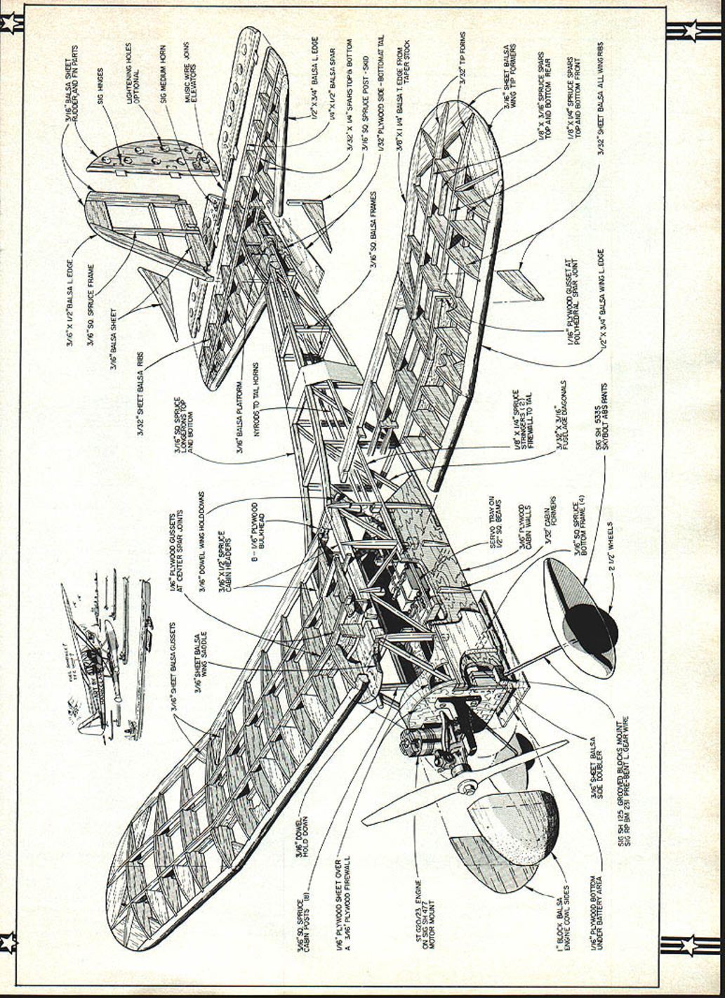
Note: No primary article text appears on one page of the original publication — it contains only the full-page exploded-view drawing of the Super Brigadier with parts labels and diagram callouts.
Several well-engineered and aerodynamically sound designs were being published. Among these were the Good Brothers' Rudderbug in MAN, May 1949; Fran McElwee's Radar in the April 1949 Air Trails; the Citizen by Bill Winter in M.A.N., February 1950; and the RC Special by Bill Winter and Walt Schroder in a 1948 Mechanics Illustrated.
The Super Brigadier becomes a design of extremely high historic interest and importance as it represents the first commercial break from the "suitable for radio control" free flight kits of the era. The Super Brigadier was relatively simple to construct, much smaller than other RC designs, and flew well. It became a "standard" for the time.
The development of this article was prompted by remarks in "For Openers" in M.A., September 1978. To quote, "These vintage R.C.s do not fly like converted free flights. In terms of power and wing loading their performance index is roughly halfway between that of the Old-Timers and modern sport low wings. These old R/C designs could be the next Klondike—gold rush, that is." It quickly became apparent that the most logical choice as a subject for a modernization was the "daddy of them all," the Super Brig. It possessed the best combination of esthetics, size and building techniques.
The resultant model has proven itself an excellent sport job. Admittedly, several major force and moment changes were needed to correct some rather alarming spiral instability problems, but the plans reflect these changes.
General
Unless otherwise noted, all adhesive joints are of aliphatic resin glue such as Sig and Tite-Bond. The term C.A. refers to cyanoacrylate adhesives, such as Hot Stuff and Super Jet. All wood sizes are standard and should not be altered. All hardware is out of my dealer's stock, with the exception of the pre-bent landing gear and the wheel pants which are available from Sig.
Drill required holes at the time the part is being cut to avoid the "forgotten hole" problem. Trial-fit parts before gluing for a snug but nonbinding fit.
A steerable tail wheel is not shown since the tail will not stay down on grass when enough power is used to move the model. The prototype used elastic bands to retain the rudder and stab unit, primarily to allow for needed incidence changes (numerous changes were needed). Now that a corrected decalage setting has been determined, I recommend epoxying the unit permanently onto the fuselage if so minded.
The servo tray is screwed onto wood strips and slid fore or aft to obtain an optimum CG, then epoxied onto the fuselage sides. I used Nyrods. Alternatively, 1/4" square balsa pushrods and clevis are satisfactory.
A superior method for pattern making is to copy the part from the plan with a Thermofax-type copier, cut the print to a rough outline, spray it with 3M Sprayment, stick it onto the appropriate sized wood and cut out on the jigsaw. Peel off the paper and an accurate, simple piece has been produced. If a copier is not available, tracing paper and a pencil may be substituted.
Wing
Make a master rib of 1/8" or 3/32" ply, using the above-mentioned technique. Cut a stack of 3/32" balsa rib blanks, pin together, and cut out the ribs on a jigsaw. The wing is built flat, requiring no shims. The tips are laid out flat, with the bottom spar ends notched into them. The steps:
- Notch preshaped T.E. stock and pin over plan.
- Cut tips to rough outline and pin onto plan.
- Locate position of lower spars using several ribs as guides.
- Glue ribs into T.E. notches and over spars.
- Notch L.E. stock and glue onto ribs.
- Slit ribs that will butt onto the center section using the angle jig.
- Add top spars and tip section fillers of scrap balsa.
- Allow at least 24 hours for glue to cure, then remove panel from drawing.
- Block up wing tip to correct outboard dihedral, using table supports and blocks to sand in the angle.
- Epoxy with tip blocked up. Use dashed outline for right panel construction.
- Repeat above steps to create a mirror-image wing panel—center section is built integrally with one of the two panels.
- Assemble panels to center section with epoxy while tip is blocked up at outboard joint.
- Use two hacksaw blades taped together to cut slots through ribs flush with the spars.
- Place ply sheet into slot, mark shape with a pencil run along the spars, remove and cut out pattern.
- Epoxy gussets liberally, holding them against the spar faces with clothespins as clamps.
This method produces plywood gussets custom-made for the wing, vastly superior to precut ones that seem to never fit well. Complete the wing by carving the L.E. to shape and sanding the tips into a blending taper.
Stabilizer and Rudder
Use the copier-Sprayment technique to produce the ribs, or merely cut blanks that can be fitted onto the spars, then block-sand to airfoil after assembly. Pin L.E., T.E. strips and tips flat over the plans, position bottom spar, then glue ribs into place. Add fillers, gussets and top spar. Carve and sand to shape, then add elevator. Hinge and epoxy the wire joiner before cutting slot into elevator. The lightening holes were fabricated by placing an X-Acto punch into a drill press and "drilling" while punching. Backing up the balsa with a piece of pine greatly reduces tearing of the wood when the "drill" penetrates.
The rudder is so simple that no explanation is needed. Just remember the filler runs to the bottom of the stab slot. Both members are covered prior to final assembly. I use toothpicks secured with C.A. to anchor the hinges. This is a simple but extremely strong technique with minimal opportunity to slop glue into the hinge.
Fuselage
Cover plan with Saran Wrap. Place previously cut 3/16" panel ply side over the plan, using pins through holes. Assemble one side and allow glue to set at least 4 to 6 hours. Remove pins that will obstruct second side, cover joints with masking tape to ease separation, then build second identical side over first. Allow overnight curing before removing sides from plan. Separate the halves using a table (casing) knife and gently pop the sides apart. Remove masking tape.
Trial-fit bulkheads A and B, then epoxy into appropriate slots in the sides. Insert assembly with wing rails over top view, pin and align for right angle relationship in both planes. Check alignment with triangles and carpenter's square. Keep the fuselage square in both dimensions by adjusting the clothespins and masking tape used to hold everything in place. Complete all cross braces and landing gear block-ply bottom.
Allow 24 hours for glue cure, then pull tailpost ends together to meet exactly over the center section of the top view. Note the tail skid member is epoxied to the outside of the tail post. Check squareness as the cross members are added. Add tailskid and subrudder, using epoxy.
Remove from board, add side stringers, tack glue and carve nose blocks. Glue ply tank floor and 3/16" tail fill-in, place window filler strips, etc. Drill gussets for dowel, but do not install until fuselage has been covered. Epoxy cabin roof in place then epoxy dowel to it (this is an excellent situation for thixotropic epoxy). Sand and shape fuselage to final form, add ply coaming and permanently epoxy nose blocks. See cross-section for clarification.
Trial-fit engine, tank, undercarriage and wheels, tail, etc., then locate position for servo tray and battery pack. Epoxy tray rail to ply side, then cut and adjust Nyrods or pushrods to fit. Try to balance. It should be slightly nose heavy at this time as the covering will move the CG rearward about 1/2" to 5/8".
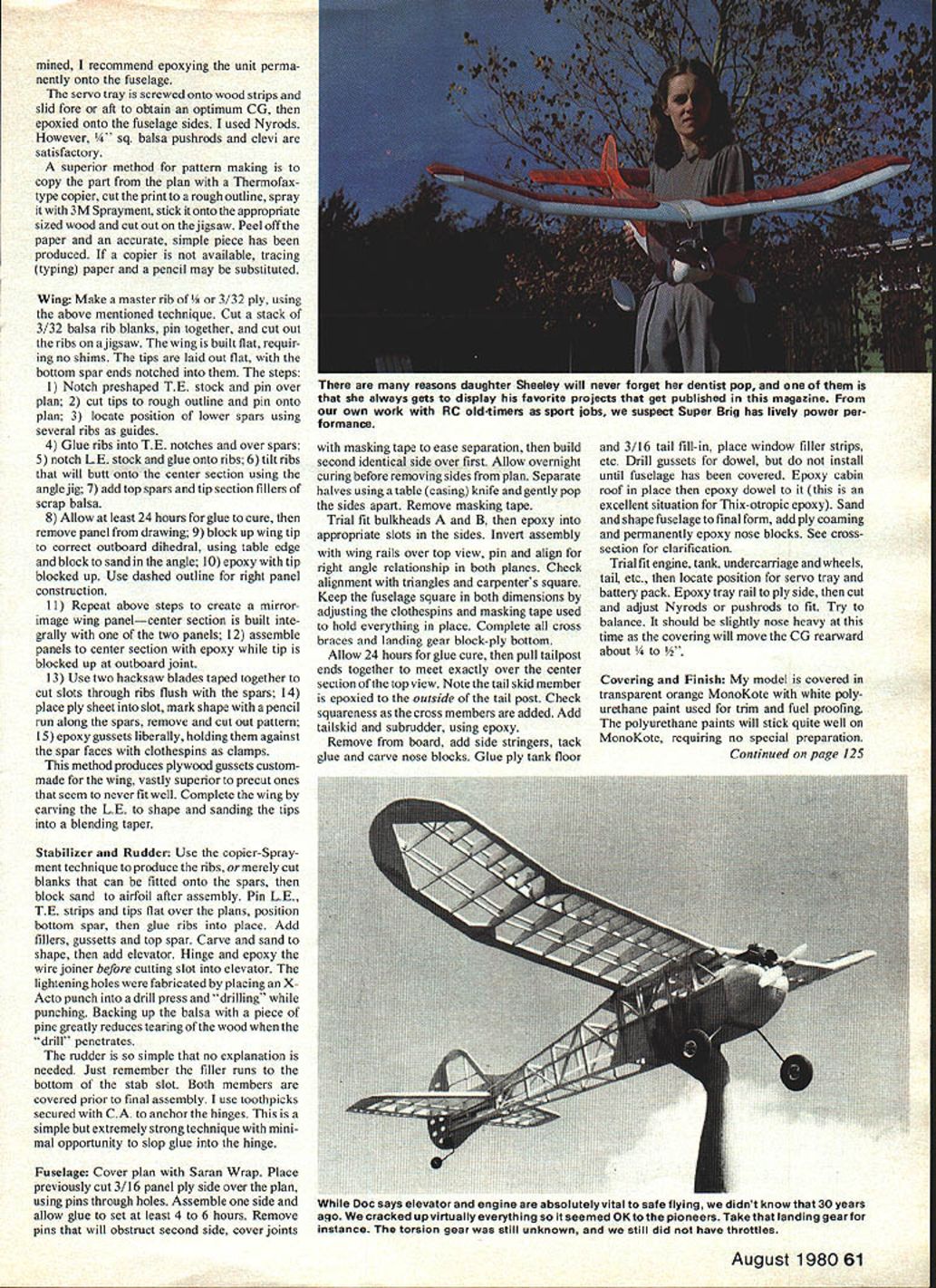
Covering and Finish
My model is covered in transparent orange MonoKote with white polyurethane paint used for trim and fuel proofing. The polyurethane paints will stick quite well on MonoKote, requiring no special preparation.
Masking is accomplished rather easily with vinyl electrician's tape which should be removed within minutes of the application of the paints.
Preflight
At this point all equipment, hardware, etc., is permanently installed and tested. Trial-run the motor and obtain a consistent carburetor setting; check operation of radio equipment with the engine running and perform a range check. All functions and operations should be checked and adjusted at home to avoid the mental errors that often result from the frustrations generated at the flying site by malfunctions. You will be tense enough without being forced to try to scrounge an Allen wrench to tighten a wheel collar, etc. Do it at home!
Check for and eliminate any warps, misalignments or deviations in CG position.
Flight
With the forces and moments set up as drawn, the Super Brigadier is a relatively docile sport-trainer. Takeoffs are essentially a throttle-rudder function requiring little application of elevator. As the throttle is advanced, feed in enough right rudder to steer the model straight ahead. Once rotation speed is reached the fin becomes effective requiring decreasing amounts of rudder. Turns are more typical of a trainer than an Old-Timer, as Bill Winter predicted. That is, little if any self correction is evident; the turn must be terminated with opposite rudder and slight up elevator. The model will groove well, but must be flown at all times, unlike an Old-Timer with its built-in stability.
Conversely, the Super Brigadier is remarkably forgiving of overcorrections and "ham-handedness," fitting into the flight performance spectrum between an A-Ray or Kadet and a true Old-Timer free-flight conversion. Stalls are "mushy" with little tendency to drop a wing or snap. With power, the Brigadier will spin after about 270 degrees of tight turn, coming off a power-on stall. These characteristics give excellent low-speed flight, producing a model that is an excellent translation between Old-Timer and basic trainer in flight.
The Super Brigadier also surprised me by teaching some lessons in aerodynamics long since forgotten. The resultant model certainly is not only possessed of a novel appearance, but fills a gaping performance range for the emerging radio flier. I would hope those who choose to construct a Super Brigadier will receive as much joy and fun as mine has given me.
Addendum
Once this article was completed and the "Brig" had filled her enjoyment quotient for me, she was sold to Bill Moore of Anthony, Kansas. His experiences so graphically illustrate the versatility of this design that Bill Winter has asked me to relate them to you.
With no instructor of any kind available to them in their small village, Bill and three friends used the Super Brig as a vehicle on which to learn to fly RC. Although none of them had ever flown an RC model, they bravely got together one Sunday afternoon and proceeded to "self-instruct" themselves. Unable to successfully take off from the dirt road they were flying from (at least initially), they opted to hand-launch the model after several ground loops. (Note: I recommend flying from short grass, not hand-launching.)
Incredible as it may seem, before sunset they all were successfully taking off, flying, and landing the Super Brig! To be sure the model exhibited some dinged wing tips, a scratched-up nose, several elastic bands were popped off, and the wheel pants were long gone, but the model was nonetheless still flyable. It had survived this extraordinary flying session by smoothing out the inevitable overcontrols of these beginners, correcting its attitude while they were getting reoriented, and forgiving them their errors. Had I not flown this model before them, I would find this story as unbelievable as you must. It is absolutely true!
In a single day this highly stable, extremely rugged, and relatively viceless model had introduced four total strangers to the joys of this hobby-sport we love so much. I know of no higher recommendation to the prospective builder.
Transcribed from original scans by AI. Minor OCR errors may remain.

