

Super Bug
D.B. Mathews
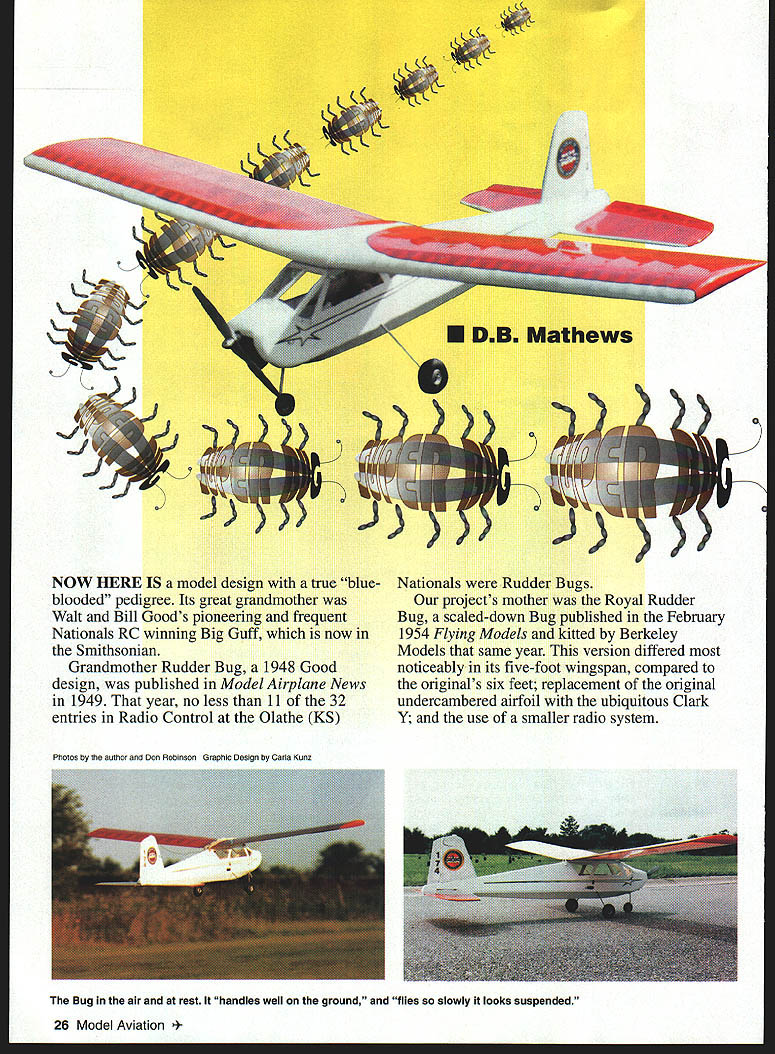
NOW HERE IS a model design with a true "blue-blooded" pedigree. Its great-grandmother was Walt and Bill Good's pioneering and frequent Nationals RC winner Big Guff, which is now in the Smithsonian.
Grandmother Rudder Bug, a 1948 Good design, was published in Model Airplane News in 1949. That year, no less than 11 of the 32 entries in Radio Control at the Olathe (KS) Nationals were Rudder Bugs.
Our project's mother was the Royal Rudder Bug, a scaled-down Bug published in the February 1954 Flying Models and kitted by Berkeley Models that same year. This version differed most noticeably in its five-foot wingspan (compared to the original's six feet), replacement of the original undercambered airfoil with the ubiquitous Clark Y, and the use of a smaller radio system.
In 1952, largely through the efforts of the AMA, the Citizen Band (27 MHz and 465 MHz) was made available exam-free (but not license-free) for modeling use. This relaxation of requirements opened the door for many for whom the Ham requirement had been an insurmountable obstacle. Several manufacturers began to market assembled and kit units and the RC segment of our hobby suddenly exited the experimenters' workshops and became a practical reality for modelers.
This new version was developed from the original Flying Models/Berkeley plans used to build a Royal Bug in 1954, powered with a greenhead K&B .19 and "controlled" with a CitizenShip radio. I carried those plans around for 42 years, thinking that some day I'd build another Royal Rudder Bug.
With the surging interest in models of those early years and the growth of the Vintage Radio Control Society (2 Hemlock Ct., Saugerties, NY 12477), I finally have been bitten by the Bug again. I dug out those old plans, enlarged the Royal to six feet, tried to eliminate some of the notorious structural weak spots, added elevator and throttle controls, a steerable nose wheel, changed the trademark side doors to top access, and reworked the aerodynamics.
For those who feel we've desecrated the spirit of the model and era, authentic drawings for the rudder-only Royal Rudder Bug are available from Bill Northrop's Plans Service (2019 Doral Court, Henderson, NV 89014). Bill also has construction drawings for several other Vintage RC designs.
With today's light, yet highly reliable proportional radio equipment, the addition of throttle and elevator, and the use of modern adhesives and covering materials, this Bug is totally different than the one I built 42 years ago. With three controls, rechargeable batteries, and vastly improved reliability, this new version actually weighs less than the original rudder-only version.
At the 1996 Celebration of Eagles in Muncie I was astonished to see Bob Noll fly an original Rudder Bug with original equipment — and fly it well. The man even did loops and rolls with rudder only!
My version handles well on the ground, flies so slowly it looks suspended, is remarkably stable and gentle, and can do the neatest touch-and-gos imaginable. All this without needing the advanced flying skills exhibited by Bob Noll or spending endless hours adjusting incredibly "fussy" radio equipment.
CONSTRUCTION
Several construction approaches are signature Walt Good techniques: building the fuselage on a crutch, the "tepee" top formers, and the method of introducing washout in the wing tips. These now-nearly-forgotten techniques add appeal to building a Bug. Its novel appearance and strong historical significance are also attractive.
Wood selection should be medium-range; sizes are standard hobby-shop stock. Hardware is off-the-shelf. Principal adhesives are cyanoacrylate (CyA) for most joints and epoxy for heavily loaded areas.
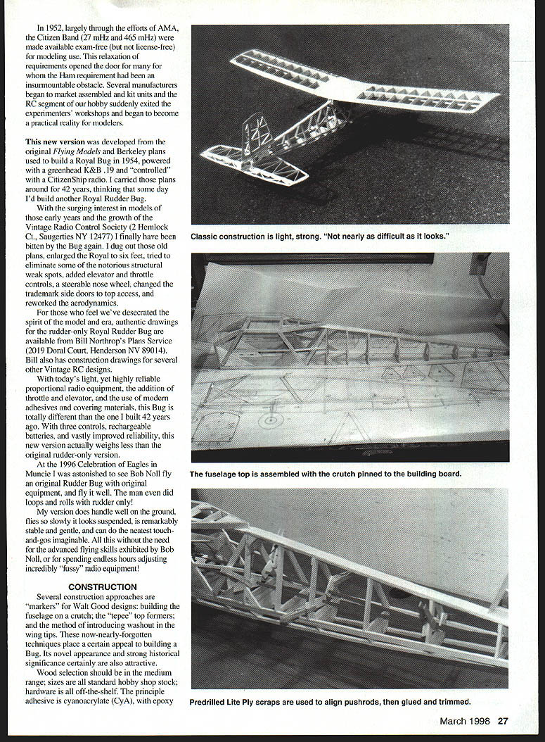
Classic construction is light, strong and nearly foolproof. A few good triangles (squareing blocks) are essential; otherwise special tools are not required. The structures are sufficiently stiff to allow use of any finishing method, from silk-and-dope to iron-on coverings. I would avoid some of the heavier prepainted heat-shrink fabric materials, however, because of weight.
Fuselage
The crutch construction is assembled directly over the top-view plan. Preassembled cabin sides and top formers are then added. Small sections of scrap 1/8" plywood adhered to the inside of the cabin sides make helpful locators when placing the sides onto the crutch. All assemblies must be at right angles to the crutch and to the building surface.
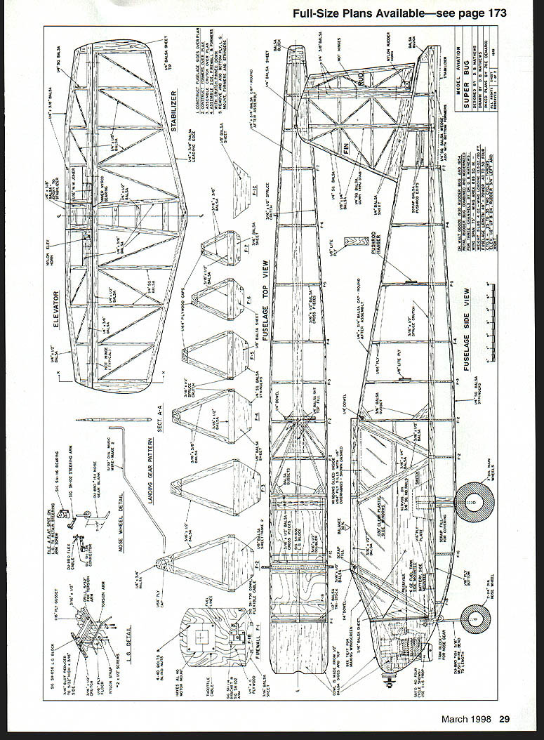
Don't forget the hole for the rudder-post in the capstrip — the post runs all the way down onto the top of the stabilizer. The firewall should be drilled for fuel lines, throttle pushrod, nose-gear rod, and engine mounts before assembly to the fuselage. The firewall is tilted forward to build in downthrust; a scrap jig is handy for checking its position.
Our photo prototype did not have the cabin sides constructed per the original drawings because I had toyed with the idea of using removable doors of the original. After thinking about it, the complexities of component access outweighed any desire for authenticity, so I subsequently sheeted in the bottom portion.
The "tepees" are assembled over the drawing and are simple to fabricate if a good razor saw is used. As with any scratch-built project, assemble the largest components first; that way, if a piece is cut short, it can still be used for the next former.
Once the sides and tepees are in place, add the forward wing-saddle framing and windshield braces; be sure they are square. The rear tapered portion of the cabin and its joint with the rear capstrip are tricky — sand slowly with a block and check fit frequently. It is essential that the wing saddle be flat and level with solid joints; if in doubt, cut a new piece rather than compromise.
With the upper fuselage still pinned to the building board, trial-fit the servos and pushrods. Scrap plywood supports, exit slots and front braces should be arranged to avoid any flexing of the rods. I use 30-inch 2-56 threaded pushrods running inside Nyrods with threaded clevises on the surface ends and solder links on the servo arms.
Remove the upper fuselage from the board and add the lower formers, plywood bottom, stabilizer-incidence strips, and landing-gear torque boxes. Note the forward block at the bottom of the firewall is actually in two pieces to create a box for the nose-gear collar. Since the main gear must be in place before covering the model, use scrap balsa filler around the wire to aid covering. Do the same around the pushrod exits at the rear.
Round the bottom stringers, the tepee cap, the rear block, and the nose blocks with 220-grit sandpaper on a block. Add gussets and reinforcing strips, and drill dowel holes, but do not adhere the dowels until final fitting.
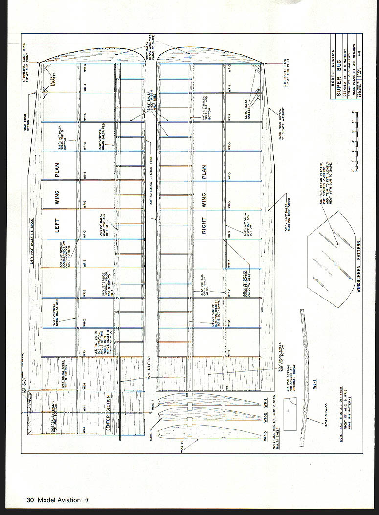
Wing
This is actually a simple wing to build. The original used interior spars in slotted ribs, which is fine for a kit but a bear to scratch-build without warps. The four-spar method I chose is not only much simpler, it is stronger. The half-ribs add mostly cosmetics and nostalgia and may be omitted if desired.
Build sequence:
- Place the bottom spars and sheeting over the plans.
- Add the ribs, leading edge, half-ribs (if used), then the top spars, shear webs, and center-section sheeting.
- Tilt the inboard ribs using the jig and trim spars flush with the ribs.
- Add tip blocks and contour them with an X-Acto and sanding blocks.
- Cut and adhere all gussets and round the leading-edge strip.
Center-section construction follows the same sequence, except the outboard ribs and spar ends are cut at right angles to the building board. Outboard wing panels are built to a full rectangle, cutting the trailing-edge slant after completing assembly. The bottoms of the ribs and the rear spars are sanded to flare into the trailing edge. This creates built-in washout, which adds tremendously to the Bug's inherent stability.
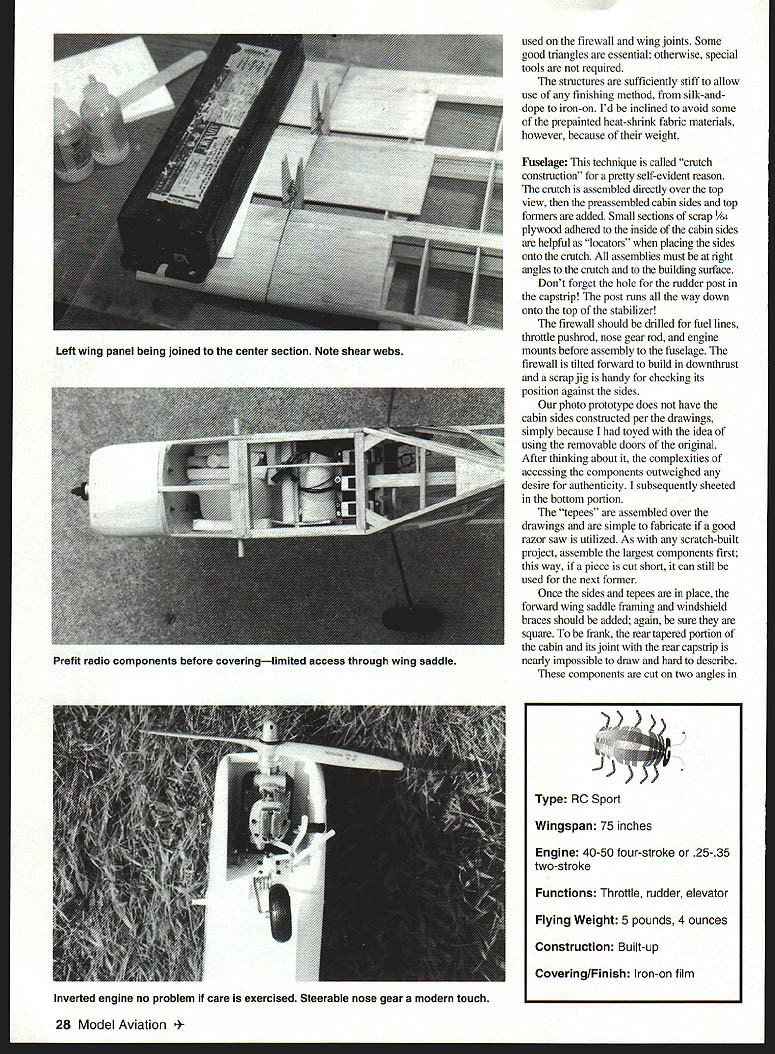
When both panels and the center section are completed, block up a tip to the dihedral measurement and block-sand the face rib parallel with a table edge. Repeat for the other panel. Join an outboard panel (blocked up) to the pinned and weighted-down center section using epoxy; when cured, repeat with the other panel.
Cut slots along the spar/rib face for the plywood dihedral braces and epoxy them in place. Complete the joint by sanding rough spots and wrapping thin glass tape with finishing epoxy resin. Install plywood rubber-band "bumpers" after glassing the center section.
The tail feathers are simple. Spars at the hinge lines should be relatively hard and absolutely unwarped. The wire elevator connector runs inside a section of inner Nyrod and is installed with the same technique used for strip aileron horns. Hinges on the 1954 version were small sections of music wire running inside brass grommets, with grommets thread-wrapped and cemented to the top and bottom of the fin. On this model I used "hot hinges" — one of the many newer products that are incomparably superior to those available 42 years ago.
Dr. Good's original Royal Rudder Bug (and earlier versions) used thin semisymmetrical airfoils for the stab and rudder. The stab was set at about 3° negative; no downthrust or wing incidence was used. These rudder-only models could sometimes be looped by climbing to considerable altitude, then using rudder to spiral down—creating sufficient speed to cause the negative stab setting to drive the model up and over into a loop when the rudder was pulled hard. Some were also flown as "rudder and elevator" with added elevator throw.
I chose to eliminate the semisymmetrical sections for construction simplicity and because engine downthrust will serve the same function. I originally set the stab at 0° incidence, but even with 7° of downthrust the Bug needed full down trim to control climb at any throttle setting above 30%. Changing the stab to 3° positive cured the unwanted climb problem.
I also increased the rudder area slightly to tighten the turn radius, particularly in super-slow flight. The dihedral angle is unchanged, which provides very positive leveling once the rudder is neutralized.
Covering and Finish
If the builder has the time, money, and skill, this project would be truly beautiful when covered in silk and clear dope. My wife is violently allergic to dope fumes, so the photo model is finished in transparent MonoKote trimmed with Rust-Oleum® paint, trim tape, and Sig Four-Star 40 wing and fuselage graphics.
I placed a 600 mAh battery pack, the receiver, and the tank on their sides with foam between them, forming a multilayered vertical sandwich just back of the firewall. Run a strip of balsa across the top to prevent vibration from lifting the parts.
Pushrod, servo, and horn installation is as the builder prefers. As suggested earlier, these components should be prefitted before covering — access through the wing saddle is limited.
Windows are installed as the last step. Use sections of clear plastic scored over the plans, popped apart, and trimmed to fit inside scrap 1/8" plywood frames. Adhere them to the inner edges with RC-56 adhesive. This technique looks neat, is utilitarian, and is simple to do.
Flying
What a joy it was to finally — after all these years — have a Bug take off gracefully, fly beautifully, and land at my feet, over and over again, with total predictability. That's what the whole project was about.
Virtues of the Bug in this new version can be summarized succinctly: this model flies like an in‑between‑size Sig Kadet Senior/Senorita — and that is a pretty good recommendation. A sound aerodynamic design is a sound design, regardless of its age.
A brief observation on inverted four‑stroke engines: many of us run strokers inverted with no particular problem. If there is a secret to successfully operating them it is:
- Never choke them.
- Be certain the fuel-tank location will not allow siphoning of fuel into the carburetor.
- Set the low-end and idle a bit lean — never rich. Almost all potential problems are associated with swamping the glow plug with fuel.
An onboard glow driver is helpful, but not essential. Don’t shy away from a project with an inverted four‑stroke engine — it’s a manageable installation.
This Bug is so simple to fly that it ranks with the best modern sport/trainers. The design would be a worthwhile building project without all the nostalgic baggage, but with that baggage it has been super‑delightful.
I suppose a purist would construct a Royal Rudder Bug exactly as originally designed, use original radio equipment of the period, Ambroid cement, silkspar, clear nitrate dope, vintage wheels, over‑and‑under fabric hinges, etc., then haul the model to the flying site in a 1952 Ford Victoria while dressed in period clothing. To each his own — whatever brings them fun.
If you have wondered how well one of these old RC designs would fly with modern radio equipment, here is a wonderful chance to find out. One warning, however: you will have a difficult time figuring out how to wind the rubber strip for the escapement.
— D.B. Mathews 909 North Maize Rd. Townhouse 734 Wichita, KS 67212
Transcribed from original scans by AI. Minor OCR errors may remain.

