
Super Burp
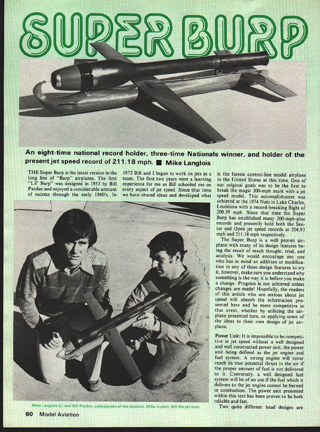
The Super Burp is the latest version in the long line of "Burp" airplanes. The first 'Lil Burp' was designed in 1953 by Bill Pardue and enjoyed considerable success through the early 1960s. In 1972 Bill and I began to work on jets as a team. The first two years were a learning experience for me as Bill schooled me on every aspect of jet speed. Since that time we have shared ideas and developed what is the fastest control-line model airplane in the United States at this time.
One of our original goals was to be the first to break the magic 200-mph mark with a jet speed model. This was achieved at the 1974 Nats in Lake Charles, Louisiana with a record-breaking flight of 200.59 mph. Since then the Super Burp has established many 200-mph-plus records and presently holds both the Senior and Open jet speed records at 204.93 mph and 211.18 mph respectively.
The Super Burp is a well-proven airplane with many design features resulting from much thought, trial, and analysis. We encourage anyone thinking of additions or modifications to try them, but make sure you understand why something is the way it is before you change it. Progress is not achieved unless changes are made. Hopefully, serious jet-speed readers will absorb the information presented here and be more competitive in that event, whether by utilizing the airplane presented here or applying some ideas to their own jet design.
Power Unit
It is impossible to be competitive in jet speed without a well-designed and well-constructed power unit — defined here as the jet engine and fuel system. A strong engine will never reach its true thrust potential in the air if the proper amount of fuel is not delivered. Conversely, a well-designed fuel system is useless if the fuel it delivers cannot be burned in combustion. The power unit presented here has proven to be both reliable and fast.
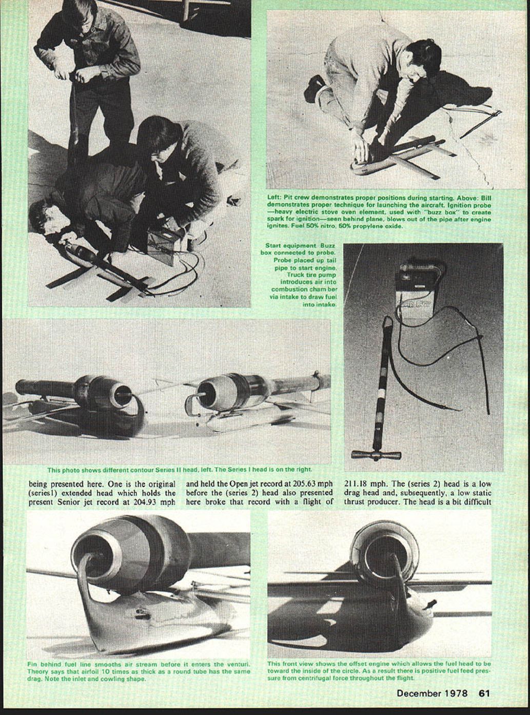
Two quite different head designs are presented. One is the original (Series 1) extended head which holds the present Senior jet record at 204.93 mph and held the Open record at 205.63 mph before the Series 2 head broke that record with a flight of 211.18 mph. The Series 2 head is a low-drag head and, subsequently, a low-static-thrust producer. The head is a bit difficult to build and to operate because of the low static thrust and low static fuel-drawing capabilities; that is, the head is difficult to keep running on the ground. Therefore, it is advisable to build a Series 1 head first (especially if you have very little jet experience) and get all you can out of it before going to a Series 2 head. The Series 2 head is about 6 mph faster than a Series 1 head with nearly all variables equal. Both heads were flown on the same airplane, using the same fuel and the same tail pipe.
I believe the Series 2 head has more potential speed because of two factors. One, both the record flight and backup flights were made with a 1/4 lap of glide at the end of the flight; therefore, if the fuel tank were larger, more speed could have been registered. Two, because of limited fuel capacity we were limited on metering jet size — we could not run a richer metering jet because we would have run out of fuel even earlier into the clocking.
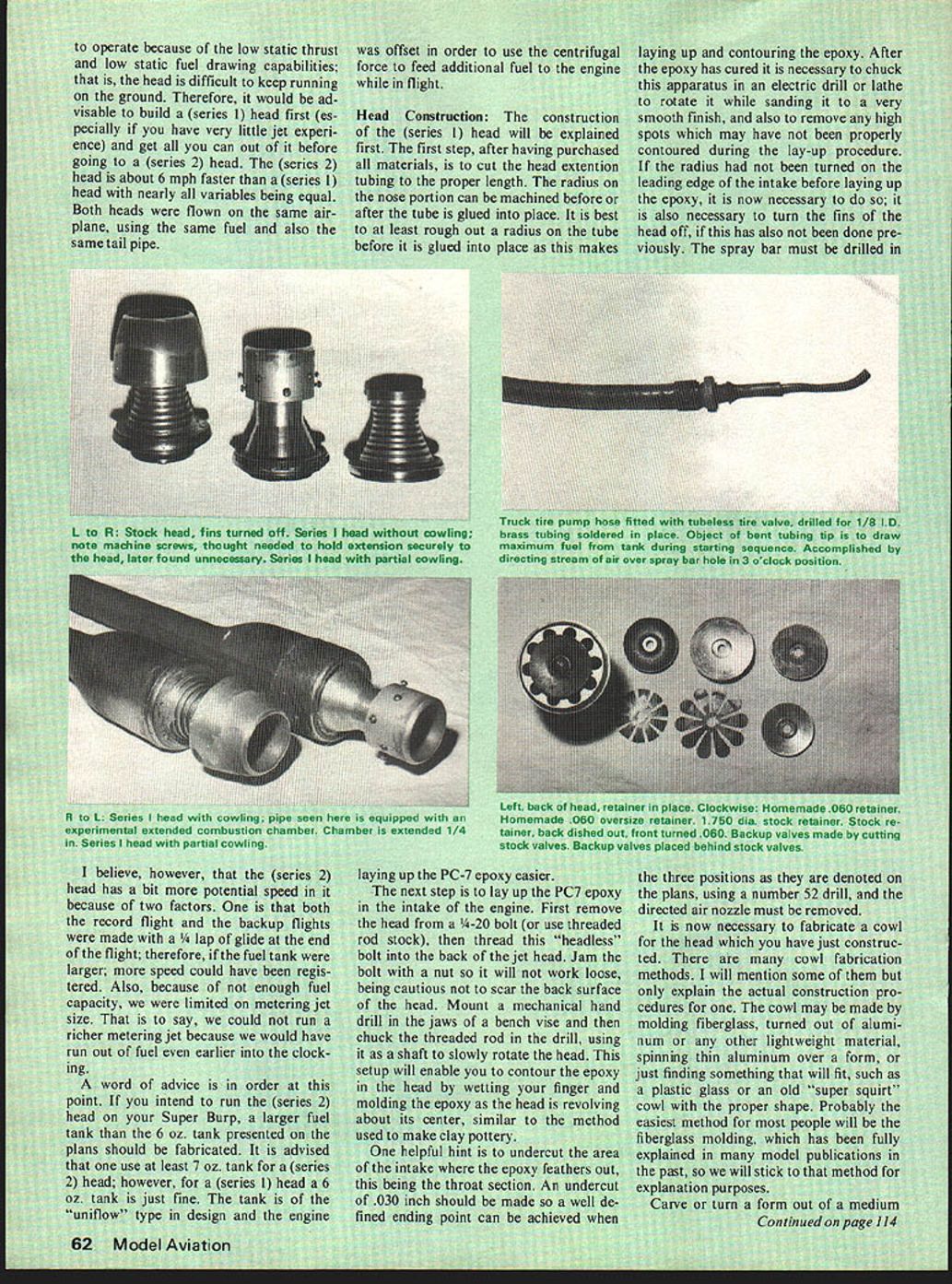
A word of advice: if you intend to run the Series 2 head on your Super Burp, fabricate a larger fuel tank than the 6 oz. tank shown on the plans. Use at least a 7 oz. tank for a Series 2 head; for a Series 1 head, a 6 oz. tank is fine. The tank is of the "uniflow" design and the engine was offset to use centrifugal force to feed additional fuel to the engine while in flight.
Head Construction
The Series 1 head construction is explained first.
- Cut the head extension tubing to the proper length.
- Rough out the radius on the nose portion before gluing the tube in place; this makes laying up and contouring the epoxy easier.
- After the epoxy cures, chuck the assembly in an electric drill or lathe and sand to a very smooth finish, removing any high spots.
- If the radius on the leading edge of the intake was not turned before lay-up, turn it now; also turn off the fins if not previously done.
- Drill the spray bar in the three positions denoted on the plans using a No. 52 drill, and remove the directed-air nozzle.
Cowl fabrication: There are many methods — molding fiberglass, turning out of aluminum, spinning thin aluminum over a form, or finding a ready-made shape such as a plastic jar or an old cowl. Fiberglass molding is likely the easiest for most people.
- Carve or turn a form from a hard piece of wood and make a copy of the cowl's shape.
- Split the form in half and cement each half to a base board about 1/2" larger overall than the cowl section.
- Finish the form and base with fiberglass resin and polish to a high luster.
- Lay up three layers of 3/8 oz. fiberglass cloth on the mold, using a good release agent.
- When the resin dries, pull each half from the mold. Join the halves using small strips of fiberglass cloth on the inside and some resin to make a good union.
- Remove rough edges and sand smooth.
Remaining operations: turn back the stock valve retainer to match the plans and fabricate backup valves. The retainer may be turned on a lathe or electric drill; make contours smooth and even. Backup valves are simply valves cut to 75% of their original radius — scribe the correct diameter around a spare valve retainer, cut with scissors, and true the diameter with a sanding belt or grinding wheel. Remove all burrs by lapping the valves with oil and 400-grit sandpaper on a smooth plate surface. Valves may last from 10 to 20 flights depending on how rich or lean the engine runs. This maintenance beats changing a prop and plug each flight and shows that jet is one of the most economical control-line speed events to maintain and fly.
The fabrication techniques for the Series 2 head are exactly the same as for the Series 1 head. The only material difference is the addition of the reducing sleeve in the nose of the Series 2 head. There is no separate construction discussion here because of the similarities; study the plans and take the time necessary to do a good job.
Tail Pipe Selection
When choosing a tail pipe, you cannot be certain it will run fast until it is flown on the airplane, but these tips may help:
- The record pipe measures approximately 19-7/32 inches in length, though longer pipes have run fast.
- The combustion chamber on the record pipe is smaller than others I’ve measured, but larger chambers have worked on other combinations.
- I look for a "fat" combustion chamber with a small radius of curvature in the chamber.
- Many fliers prefer to run a new pipe every contest, but the pipe used for my records is about 20 years old.
- Keep trying different pipes until you find the best one for your combination.
It is interesting to note the record-setting Super Burp (205.63 mph) airplane and engine, including the valve retainer, were constructed without a lathe — only an electric drill. The theme of the Super Burp project has been to go fast and keep it simple. Anyone with an average workshop can build a Super Burp.
Airframe Construction
Begin with the fuel tank. If the materials needed to construct the tank cannot be purchased locally, consult the materials index appearing at the end of the article.
Fuel tank fabrication (example method using a flashlight body):
- Dismantle the flashlight and sand the open end and the switch area so solder will flow properly.
- Locate a form to shape the rear section of the tank (a pool stick works well). If unavailable, fabricate or find an alternative form.
- Form the tank and solder the vent and pickup lines into the flashlight part.
- Join the front and rear parts of the tank and solder. Do not seal the rear portion yet; boil the tank in water to remove remaining flux from the interior.
- After boiling and checking line placement, form and solder the rear cap in place.
Assuming the head and cowling are fabricated, begin the engine mounting system. The installation described corresponds to the engine setup presented here; alternative mounting systems should be strong enough to pass a 40-lb AMA pull-test.
- Select a rigid material for the engine head mounting bracket (e.g., .060" stainless steel or material of equivalent strength).
- Make a pattern from the plans and transfer it to the chosen material.
- Saw the general shape, finish with a file, and drill mounting holes to correspond to the engine head and the fuselage.
- Bend the mount so the engine sits at the proper height above the fuselage.
Fuselage construction:
- Select a good hard piece of pine or basswood and transfer the fuselage pattern.
- Saw out the shape and hollow so the tank fits snugly; hollow the rear section for control movement.
- Fasten the forward engine mounting bracket in place: drill fuselage holes corresponding to the mount, groove the body for blind nut placement, pull blind nuts into position, and cement them in place.
- Cement the tank into place using a good-quality epoxy and fair the tank to the fuselage with fillets.
Fillets and covering:
- Balsa fillets are best; an epoxy filler may suffice in the interest of time.
- Contouring and filleting add strength, durability, and streamlining.
- Cover the entire fuselage — except where the wing, fuselage cap strip, and stabilizer mount — with 3/4 oz. fiberglass cloth and resin.
Skids and mounting:
- Install nose and tail skids. Bend skids to the contour of the lower fuselage and make 90° bends on each end so the ends protrude about 1/8" into the fuselage. Avoid puncturing the fuel tank. Fasten skids with good epoxy.
Wing construction:
- Select very rigid basswood, pine, or poplar. The wing should be as rigid and thin as possible without sacrificing stiffness. Wing flutter or flex can cost considerable speed.
- On the record airplane, wings were later covered with three layers of fiberglass cloth to improve strength and rigidity.
- Transfer the wing outline, saw to shape, and block-sand edges.
- Transfer the centerline and split the wing along it; use the smallest blade available for a neat rejoin.
- Groove the wing to accept the monoline unit and the control-line attachment.
- Install tip weight and bearing. Without tip weight, takeoffs are almost impossible; the model tends to spin in on launch. (If you use a takeoff dolly, the tip weight may be omitted.)
- Make a neat torque-unit installation and ensure the line groove is the proper size; stiff control is difficult to fly.
- Shape the airfoil carefully: no positive or negative incidence, no wash-in or wash-out. Set the wing zero-zero. Leave the center section unairfoiled for easier alignment and mounting.
- Finish sanding with medium-grit sandpaper.
Stabilizer construction:
- Construct similar to the wing: prioritize rigidity, thinness, alignment, and free-moving controls.
- Plastic hinges are not sacred; use any hinging method of equal strength. Jet hinges usually take extra abuse from ground contacts and harder landings.
Assembly:
- Fabricate a pushrod from 3/32" music wire fitted with a Kwik Klip to link the torque unit to the elevator control. This allows control adjustment.
- Mount the engine on the fuselage and rubber-band the stabilizer and wing in approximate position.
- Adjust wing and stabilizer location so balance is 1/8" ahead of the C.G. location denoted on the plans. Note: all C.G. references are relative to the wing, not the fuselage.
- When proper balance is achieved, glue flying surfaces in place using a slow, hardening epoxy. Dowel-pin the wing to the fuselage by drilling three 3/16" holes through the center section about 1/4" into the fuselage and fit hardwood dowels glued in place.
- Fillet the wing and stabilizer to the fuselage (fiberglass recommended).
- Add the rear cap strip to the top rear of the fuselage and contour it to the fuselage shape.
Rear engine mounting bracket and pipe clip:
- Fabricate the rear engine mounting bracket from 1/4" or 3/16" aluminum stock and airfoil it to shape.
- Suggested mounting methods:
- Drill bracket as denoted on the plans with a 6-32 clearance drill; drill into the fuselage at least to the center position. Pull blind mounting nuts into place and secure.
- Drill and tap the bracket for two 6-32 machine screws; drill the fuselage all the way through with a clearance drill so the screws run up through the fuselage and thread into the bracket. This second method was used on the record airplane and is of equivalent strength and easier to install.
- Form the pipe-retaining clip from .020" steel or stainless-steel stock (stainless preferred). Fasten the clip to the bracket with one 4-40 machine screw.
Finishing:
- Sand the entire airplane smooth. Fill nicks, cracks, or holes with filler and sand.
- Use any fuel-proof finishing technique you prefer. The record airplane finish is two coats of Hobbypoxy clear (sanded between coats) and two coats of Super Poxy color (first brushed and sanded, last coat sprayed).
Flying
Fuel and metering:
- The fuel used for all records was 50% nitromethane and 50% propylene oxide. Some success has been had by varying the nitro-propyl ratio slightly to suit weather conditions.
- Metering-jet recommendations:
- Series 1 head: No. 46 (.081" dia.) drill works best.
- Series 2 head: No. 42 (.0935" dia.) drill recommended.
- Drill metering jets Nos. 42 through 53. Larger metering jets can be made from Dooling needle-valve fittings or similar brass fittings, provided they seat properly in the spray bar or an O-ring is used to seal them.
Trial and tuning:
- Only trial and error will determine the best metering jet for your engine/airplane combination.
- Make first-flight attempts with the richest metering jet that will run while the ship is hand-held on the ground.
- If the engine cuts off after release, try the next smaller metering jet until it keeps running.
- The usual rule with an "upright" engine design is: the richer you run, the faster you go. Uprights usually lean out from start to finish, although the Super Burp’s uniflow tank tends to minimize this change. This is not universal; try leaning down one metering jet after running as rich as possible.
Starting and flying technique:
- Use a truck tire pump or any source of compressed air to start the engine.
- Use a "buzz box" with a "probe" to supply the spark for ignition. The probe we use is an electric stove oven element; cut the end off and protrude it to the approximate spark-plug location in the tail pipe. Used elements can be obtained from local appliance stores.
- On takeoff, make sure the line is taut and be ready to pull the airplane from the pitman's hand as he releases it. The airplane can be skidded off without a dolly, though a properly designed dolly should work well.
- After takeoff, get into the pylon as soon as possible and fly in as near a perfect groove as possible. Jets are more susceptible to extreme speed loss from deviating from a perfect groove than propeller aircraft.
Good luck with your Super Burp. If you have questions, feel free to contact:
Mike Langlois 2408 W. Cornwallis Dr. Greensboro, NC 27408
Transcribed from original scans by AI. Minor OCR errors may remain.

