
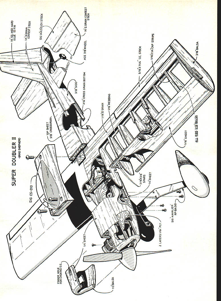
Super Doubler II
Brad Shepherd
Some say it is a revolution, and I suppose that is quite true considering the long years we have used only the high-rpm, over-square, piped two-cycle engines. Revolution may be too strong a word, but for sure the four-cycles are here to stay.
One can get a little carried away with all the raves in the modeling publications. For me the challenge of getting a smoker system to work with a four-cycle was enough for me to jump in head first. Checking my financial status and credit rating at the bank, I found I could purchase an O.S. .40 four-stroker to get things started.
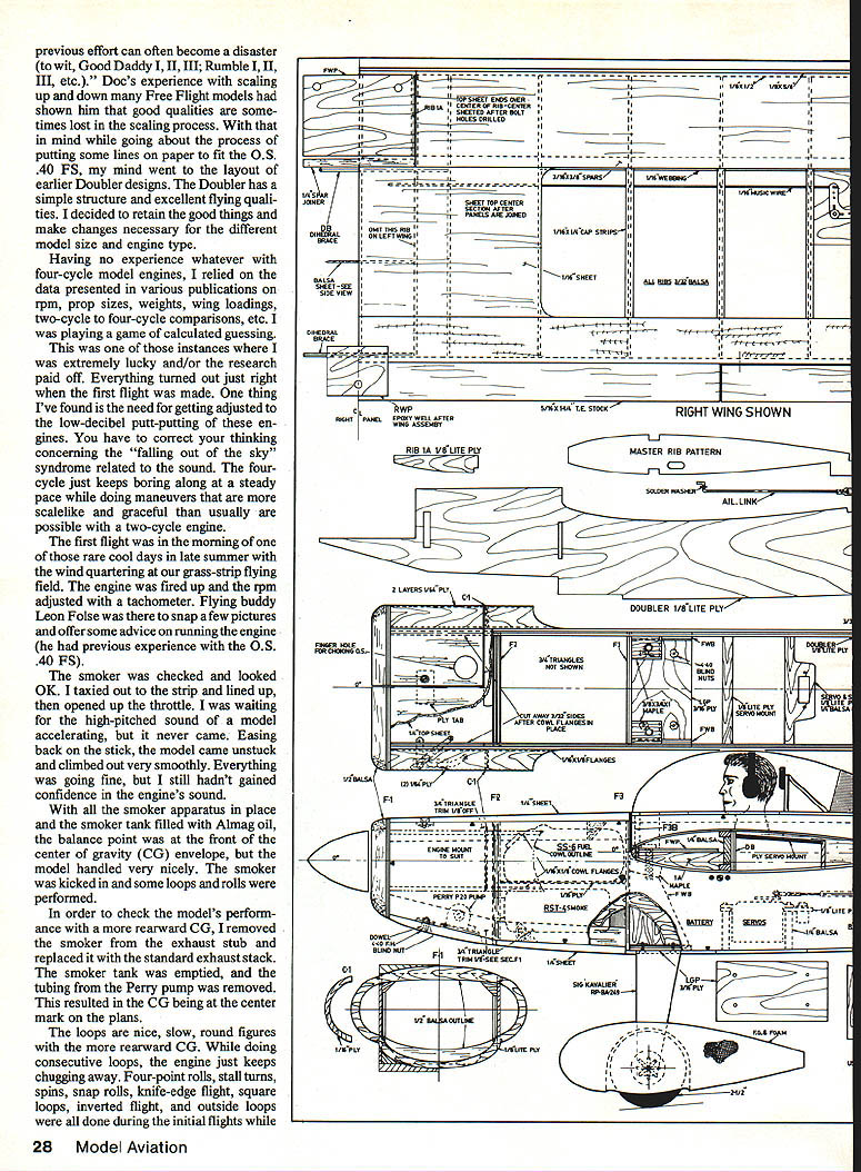
Doc Mathews, one of today's more prolific model designers, made an interesting statement: "A sequel to a highly-successful previous effort can often become a disaster with Good Daddy III, Rumble III, etc." Doc's experience scaling up and down Free Flight models showed him good qualities sometimes lost in the scaling process. With this in mind I went about the process of putting some lines on paper to fit an O.S. .40 FS. My mind went to layouts of earlier Doubler designs. The Doubler has a simple structure and excellent flying qualities. I decided to retain the good things and make changes necessary for the different model size and engine type.
Having no experience whatever with four-cycle model engines, I relied on data presented in various publications — rpm, prop sizes, weights, wing loadings, two-cycle/four-cycle comparisons, etc. Playing the game of calculated guessing in instances, I was extremely lucky and/or my research paid off. Everything turned out just right on the first flight.
One thing I've found in getting adjusted to the low-decibel putt-putting engines is to have the correct thinking concerning the "falling out of the sky" syndrome related to sound. The four-cycle just keeps boring along at a steady pace, and while doing maneuvers scale-like graceful flight is usually possible where a two-cycle might not be.
The first flight was on a cool morning late in the summer with a quartering wind at the grass-strip flying field. The engine fired up and rpm was adjusted on the tachometer. My flying buddy Leon Folse snapped a few pictures and offered some advice on running the engine from his previous experience with an O.S. .40 FS. The smoker was checked and looked OK. I taxied out to the strip, lined up and opened up the throttle. The high-pitched sound of the model accelerating never came. Easing back on the stick the model came unstuck and climbed out very smoothly.
Everything was going fine, but I still hadn't gained confidence in the engine's sound. With the smoker apparatus in place and the smoker tank filled with Ahnag oil, the balance point was at the front of the CG envelope and the model handled very nicely. The smoker kicked out some smoke and rolls performed in order. To check the model's performance I moved the CG rearward, removed the smoker exhaust stub and replaced it with the standard exhaust stack. With the smoker tank emptied and the tubing and Perry pump removed, the CG was at the center mark on the plans. The plane did nice slow, round loops; with the rearward CG it did consecutive loops — the engine just kept chugging away.
Four-point rolls, stall turns, spins, snap rolls, knife-edge flight, square loops, inverted flight, and outside loops were all done during the initial flights.
Running a Zinger 11-6 prop, the slower, steady flight is a real pleasure.
The Super Doubler II closely resembles earlier Doublers with the exception of the front end. I also used a technique to make the fuselage more shapely as I did on my Stephens Akro, Laser, and Sorta Pitts designs. It provides a pleasing form with very little more effort than it takes to produce a Stik (Ugly, etc.) fuselage.
The wing is MonoKoted while the fuselage and tail section get a dope-finish covering. Lightweight silkspan was used on my previous models to cover the grain and toughen the wood. On the Super Doubler II I used Sig's Plyspan with the shiny side out. It now looks like Plyspan will be my covering material of choice. Compared to silkspan, it is lighter, easier to apply after one coat of uncut dope, and comes up to a nice finish sooner.
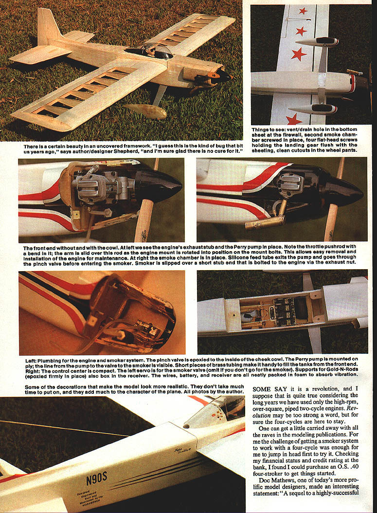
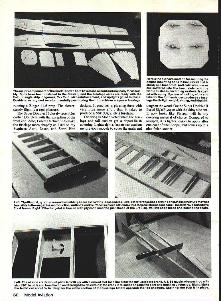
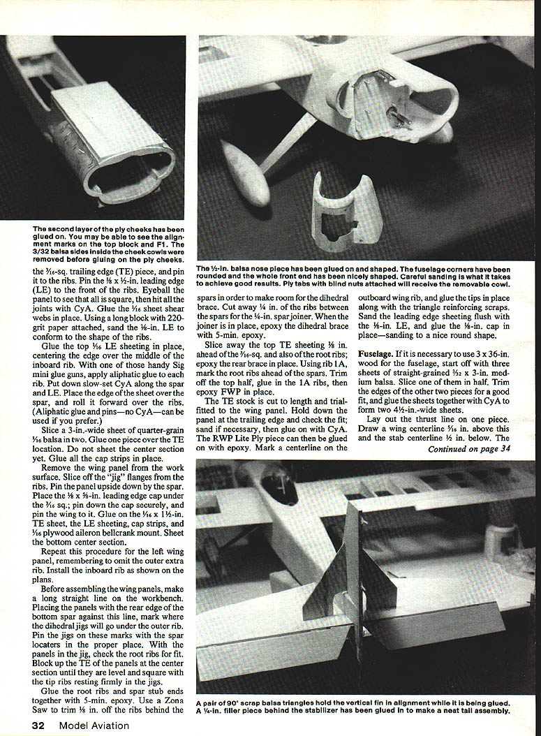
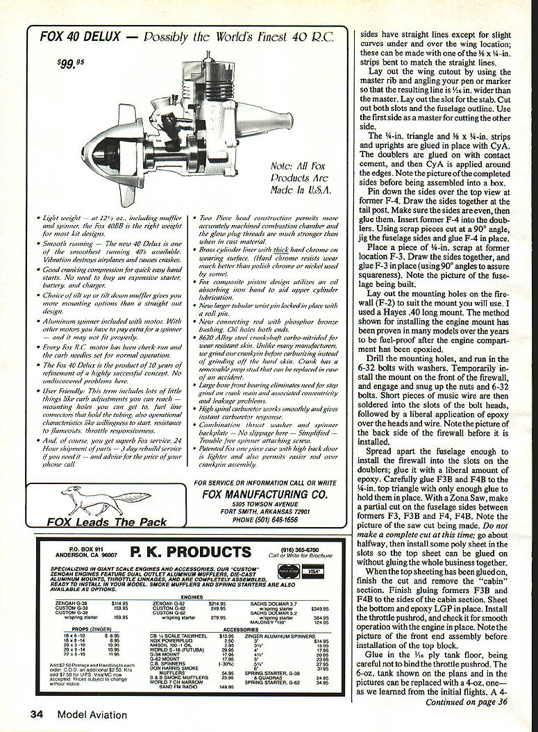
Here's my method for securing the engine mounting bolts to the firewall that is sturdy and fuel-proof. Anti-twist wire pieces are soldered into the head slots, and the whole business, including washers, is located with epoxy. A system of locking slots and tabs for the formers/sides produces a fuselage that is lightweight, strong, and straight.
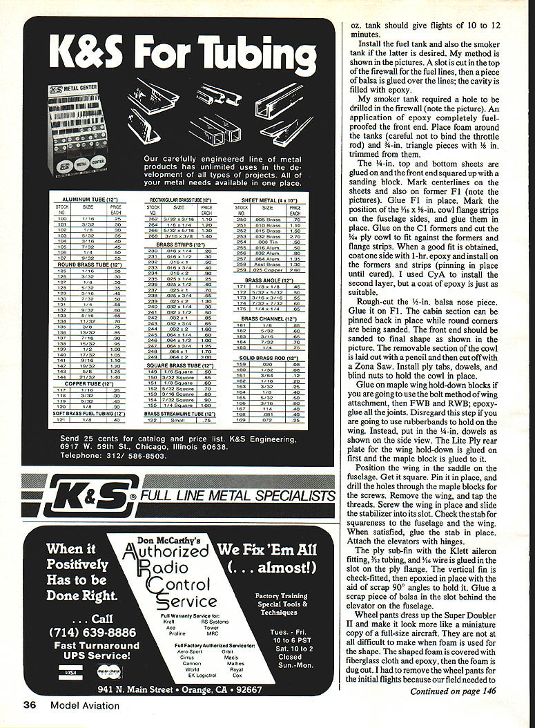
Left: Tip dihedral jig is in place on the building board as the wing is assembled. Straight reference lines drawn beneath the structure may not be visible in magazine reproduction. My work surface is a piece of Celotex laid atop an interior door panel, the latter supported by a 2 x 4 frame. Right: Dihedral joint is braced with plywood inserted just ahead of the 3/16-sq. trailing edge piece and behind the spars.
Left: The aileron crank mount plate is 1/16 ply with a curved slot for a link from the 90° Goldberg crank. A 1/16 music wire pushrod with short 90° bend is slid from the tip end through the rib cutouts; the crank is raised to engage the bent end from the underside. Right: Make the initial cut about 1/2 in. deep for the cabin section of the fuselage before applying the top sheeting. Cabin former F3B in place.
With the smoke system and its fifth servo included, my model weighs a little over 5 lb. If the smoke system were omitted and a 4-oz. fuel tank used, the model should weigh about 4 lb., 10 oz.
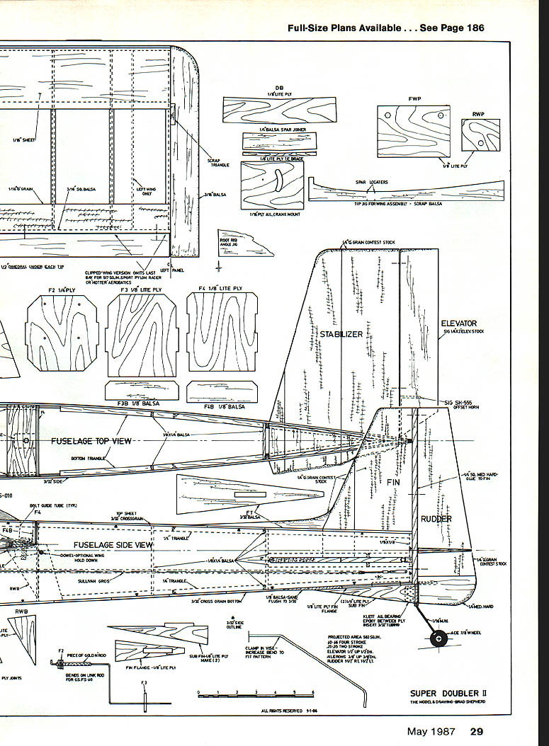
Recommended control throws are shown on the plans. The model flies well with this setup, but you should really consider the recommendations to be only a starting point from which to adjust the throws to satisfy your flying style. If you decide on a clipped-wing version, leave the ailerons 15 in. long and move them in one bay.
Smoker System
The smoker unit for the exhaust stack is quite simple to make with standard K&S tubing.
- A piece of 5/32 tubing is flared on one end and cut off 3/4 in. long to receive the O.S. exhaust pipe nut and seat it on the copper gasket.
- The smoke chamber is made from 5/8-in. tubing with a piece of 5/16 tubing silver-soldered to it so the unit can be slipped over the 3/8 tubing.
- The 1/8-in. oil feed tubing is silver-soldered to the 5/16-in. tubing just aft of the 5/16 tubing. The unit is packed with fine steel wool to flash off the oil as it passes over the wool.
- The Perry P-20 pump works great for this installation. The exit line from the pump passes through a simple open/shut pinch valve that crimps the silicone tubing.
- The Perry pump is mounted on 1/8-in. Lite Ply, and the Lite Ply is epoxied to the bottom 1/4-in. sheet. The fifth servo is operated from the landing gear switch on the transmitter to actuate the pinch valve.
This smoker arrangement, of course, is just a starting point. It works reliably now, but when new ideas come forth from others, we might see some improvements.
Construction
Start by making a kit of parts and checking that they fit. You may be surprised at how fast the model goes together. Select your balsa carefully, staying away from hard, heavy stock. You could substitute straight-grained 1/8-in. sheet balsa of medium weight for the tail surfaces (instead of 1/4-in. contest balsa) to save a bit of money.
I used cyanoacrylate glues (CyA) for most of the building. Epoxy was used on plywood parts, and aliphatic resin was used on the wing sheeting.
The fuselage is over 36 in. long. If you do not have matched sides from a balsa supplier, the front can be the "short" end, with a small piece glued to the bottom of the doubler. A long flat workbench or other working space is a must to achieve a straight wing. An interior door from a lumberyard is an excellent surface for model building.
Wing
- Cut out 22 ribs from medium-weight, quarter-grain balsa. Pin the bottom spar in place over the plans, then place the ribs in the proper location. On the right wing panel, omit the rib in between the last bay.
- Pin down each rib at the temporary flange on the trailing edge of each. Place the top spar and check that the ribs are standing vertically except for the root rib. Position the 5/16-sq. trailing edge (TE) piece, and pin it to the ribs. Pin the 1/4-in. leading edge (LE) to the front of the ribs. Eyeball the panel to see that all is square, then let all the joints cure with CyA.
- Glue the 1/16-in. sheet shear webs in place. Using a long block with 220-grit paper attached, sand the 1/16-in. LE to conform to the shape of the ribs.
- Glue the top 1/16-in. LE sheeting in place, centering the edge over the middle of the inboard rib. With a Sig mini glue gun, apply aliphatic glue to each rib. Put down slow-set CyA along the spar and LE. Place the edge of the sheet over the spar, and roll it forward over the ribs. (Aliphatic glue and pins—no CyA—can be used if you prefer.)
- Slice a 3-in.-wide sheet of quarter-grain 1/16-in. balsa in two. Glue one piece over the TE location. Do not sheet the center section yet. Glue all the cap strips in place.
- Remove the wing panel from the work surface. Slice off the "jig" flanges from the ribs. Pin the panel upside down by the spar. Place the 1/8 x 3/8-in. leading edge cap under the 1/16-in. sq.; pin down the cap securely, and pin the wing to it. Glue on the 1/16 x 1/2-in. TE sheet, the LE sheeting, cap strips, and 1/16 plywood aileron bellcrank mount. Sheet the bottom center section.
- Repeat this procedure for the left wing panel, remembering to omit the outer extra rib. Install the inboard rib as shown on the plans.
Before assembling the wing panels, make a long straight line on the workbench. Placing the panels with the rear edge of the bottom spar against this line, mark where the dihedral jigs will go under the outer rib. Pin the jigs on these marks with the spar locators in the proper place. With the panels in the jig, check the root ribs for fit. Block up the TE of the panels at the center section until they are level and square with the tip ribs resting firmly on the jigs.
Glue the root ribs and spar stub ends together with 5-min. epoxy. Use a Zona Saw to trim 1/8 in. off the ribs behind the spars in order to make room for the dihedral brace. Cut away 1/4 in. of the ribs between the spars for the 1/4-in. spar joiner. When the joiner is in place, epoxy the dihedral brace with 5-min. epoxy.
Slice away the top TE sheeting 1/8 in. ahead of the 1/16-in. sq. and also of the root ribs; epoxy the rear brace in place. Using rib 1A, mark the root ribs ahead of the spars. Trim off the top half, and use the 1A ribs, then epoxy FWP in place.
The TE stock is cut to length and trial-fitted to the wing panel. Hold down the panel at the trailing edge and check the fit; if necessary, glue on with CyA. The RWP Lite Ply piece can then be glued on with epoxy. Mark a centerline on the outboard wing rib, and glue the tips in place along with the triangle reinforcing scraps. Sand the leading edge sheeting flush with the 1/8-in. LE, and glue the 1/4-in. cap in place—sanding to a nice round shape.
Fuselage
If it is necessary to use 3 x 36-in. wood for the fuselage, start off with three sheets of straight-grained 3/32 x 3-in. medium balsa. Slice one of them in half. Trim the edges of the other two pieces for a good fit, and glue the sheets together with CyA to form two 4-1/2-in.-wide sheets.
Lay out the thrust line on one piece. Draw a wing centerline 5/8 in. above this and the stab centerline 1/2 in. below. The sides have straight lines except for slight curves under and over the wing location; these can be made with one of the 1/4 x 1/4-in. strips bent to match the straight lines.
Lay out the wing cutout by using the master rib and angling your pen or marker so that the resulting line is 1/16 in. wider than the master. Lay out the slot for the stab. Cut out both slots and the fuselage outline. Use the first side as a master for cutting the other side.
The 3/16-in. triangle and 1/8 x 1/4-in. strips and uprights are glued in place with CyA. The doublers are glued on with contact cement, and then CyA is applied around the edges. Note the picture of the completed sides before assembly into a box.
Pin down the sides over the top view at former F-4. Draw the sides together at the tail post. Make sure the sides are even, then glue them. Insert former F-4 into the doublers. Using scrap pieces cut at a 90° angle, jig the fuselage sides and glue F-4 in place.
Glue F-3 in place (using 90° angles to assure squareness). Lay out the mounting holes on the firewall (F-2) to suit the mount you will use. I used a Hayes .40 long mount. The method shown for installing the engine mount has been proven in many models over the years to be fuel-proof after the engine compartment has been epoxied. Drill the mounting holes, and run in the 6-32 bolts with washers. Temporarily install the mount on the front of the firewall, and engage and snug up the nuts and 6-32 bolts. Short pieces of music wire are then soldered into the slots of the bolt heads, followed by a liberal application of epoxy over the heads and wire.
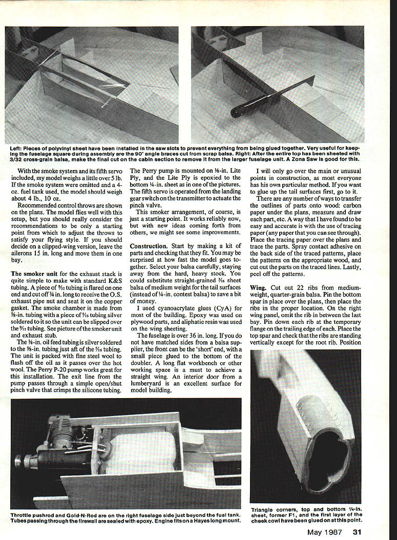
Spread apart the fuselage enough to install the firewall into the slots on the doublers; glue it with a liberal amount of epoxy. Carefully glue F3B and F4B to the in-top triangle with only enough glue to hold them in place. With a Zona Saw, make a partial cut on the fuselage sides between F3, F3B and F4, F4B. Do not make a complete cut at this time; go about halfway, then install some poly sheet in the slots so the top sheet can be glued on without gluing the whole business together.
When the top sheeting has been glued on, finish the cut and remove the "cabin" section. Finish gluing formers F3B and F4B to the sides of the cabin section. Sheet the bottom and epoxy LGP in place. Install the throttle pushrod and check it for smooth operation with the engine in place.
Glue in the ply tank floor, being careful not to bind the throttle pushrod. The 6-oz. tank shown on the plans and in the pictures can be replaced with a 4-oz. one — as we learned from the initial flights. The 4-oz. tank should give flights of 10 to 12 minutes.
Install the fuel tank and also the smoker tank if the latter is desired. My method is shown in the pictures. A slot is cut in the top of the firewall for the fuel lines, then a piece of balsa is glued over the lines; the cavity is filled with epoxy.
My smoker tank required a hole to be drilled in the firewall. An application of epoxy completely fuel-proofed the front end. Place foam around the tanks (careful not to bind the throttle rod) and 3/4-in. triangle pieces with 1/8 in. trimmed from them.
The 1/4-in. top and bottom sheets are glued on and the front end squared up with a sanding block. Mark centerlines on the sheets and also on former F1. Glue F1 in place. Mark the position of the 1/16 x 3/8-in. cowl flange strips on the fuselage sides, and glue them in place. Glue C1 formers and cut the 3/4 ply cowl to fit against the formers and flange strips. When a good fit is obtained, CA one side with 1-hr. epoxy and install on the formers and strips (pinning in place until cured). I used CyA to install the second layer, but a coat of epoxy is just as suitable.
Rough-cut the 1/2-in. balsa nose piece. Glue it on F1. The cabin section can be pinned back in place while round corners are being sanded. The front end should be sanded to final shape. The removable section of the cowl is laid out with a pencil and then cut off with a Zona Saw. Install ply tabs, dowels, and blind nuts to hold the cowl in place.
Glue on maple wing hold-down blocks if you are going to use the bolt method of wing attachment, then FWB and RWB; epoxy-glue all the joints. Disregard this step if you are going to use rubber bands to hold on the wing. Instead, put in the 1/4-in. dowels as shown on the side view. The Lite Ply rear plate for the wing hold-down is glued on first and the maple block is glued to it.
Position the wing in the saddle on the fuselage. Get it square. Pin it in place, and drill the holes through the maple blocks for the screws. Remove the wing, and tap the threads. Screw the wing in place and slide the stabilizer into its slot. Check the stab for squareness to the fuselage and the wing. When satisfied, glue the stab in place. Attach the elevators with hinges.
The ply sub-fin with the Klett aileron fitting, 3/32 tubing, and 1/16 wire is glued in the slot on the ply flange. The vertical fin is check-fitted, then epoxied in place with the aid of scrap 90° angles to hold it. Glue a scrap piece of balsa in the slot behind the elevator on the fuselage.
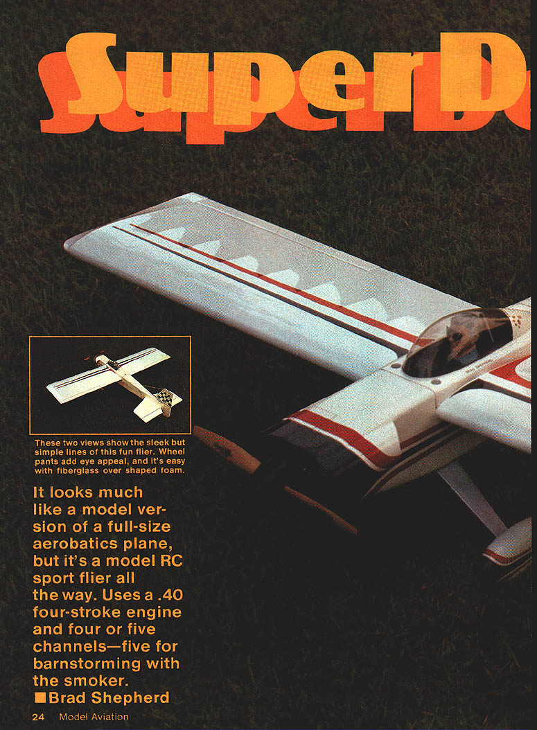
Wheel pants dress up the Super Doubler II and make it look more like a miniature copy of a full-size aircraft. They are not all difficult to make when foam is used for the shape. The shaped foam is covered with fiberglass cloth and epoxy, then the foam dug out. I had to remove the wheel pants for the initial flights because our field needed to be mowed; the grass was a little too tall.
The lettering on my model was done with dry transfers from an art supply store. A coat of clear Sig Skybrite was applied over them for protection. The sponsor decals on the canopy are from model auto decal sheets, and the pilot head started out as a Williams Bros. figure. The back side of the goggles was painted with black enamel to give the appearance of sunglasses.
I'm pleased with the way this project has turned out. It is easy to build, and it flies very nicely. I will either clip the current wing or build another with reduced span. I will also be trying other engines. A model class that is becoming quite popular with local clubs is a "500" sport racer with stock Royal .25s or H.P. .25s. A clipped-wing version should fit right in with this expanding pylon racing event.
For the most part the model is quite a change of pace. If you decide to build it, I hope you will have fun and enjoy it. Remember, four-cycles don't scream; they just putt-putt!
Transcribed from original scans by AI. Minor OCR errors may remain.

