
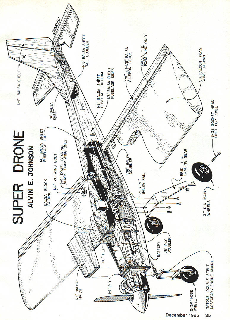
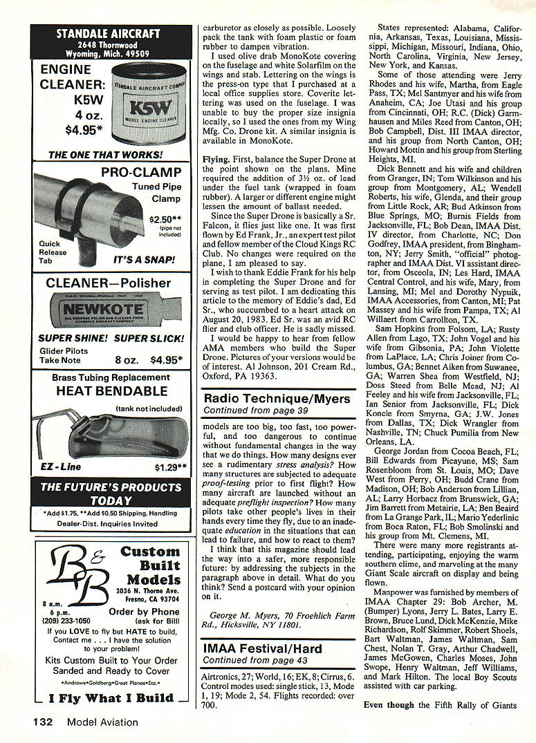
SUPER DRONE
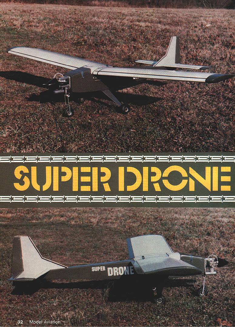
Opposite page: Antenna wire and charger plug exit neatly out the left side of the fuselage (not visible in the upper picture). Ground handling is very stable with the high and wide landing-gear arrangement, and it saves a lot of propellers at the same time.
THE INSPIRATION
The inspiration for this airplane came several years ago when Wing Mfg. Co. marketed its Drone kit. I wanted something larger and more powerful while still retaining the military appearance; this model is the result.
Rather than designing an entire airplane from scratch, I modified an existing kit model: the Goldberg Sr. Falcon. The airplane presented here was scratch-built using Sr. Falcon kit parts for patterns. If you wish to build it, there are several choices to make construction easier:
- Use the Sr. Falcon kit and make the necessary changes.
- Build the fuselage from the accompanying plans and use a kit wing/stab.
- Obtain a Wing Mfg. Co. foam wing and stabilizer kit (Wing Mfg., P.O. Box 33, Crystal Lake, IL 60014).
- Purchase a Sr. Falcon wing and stabilizer kit in wood from Carl Goldberg Models (4735 West Chicago Ave., Chicago, IL 60051).
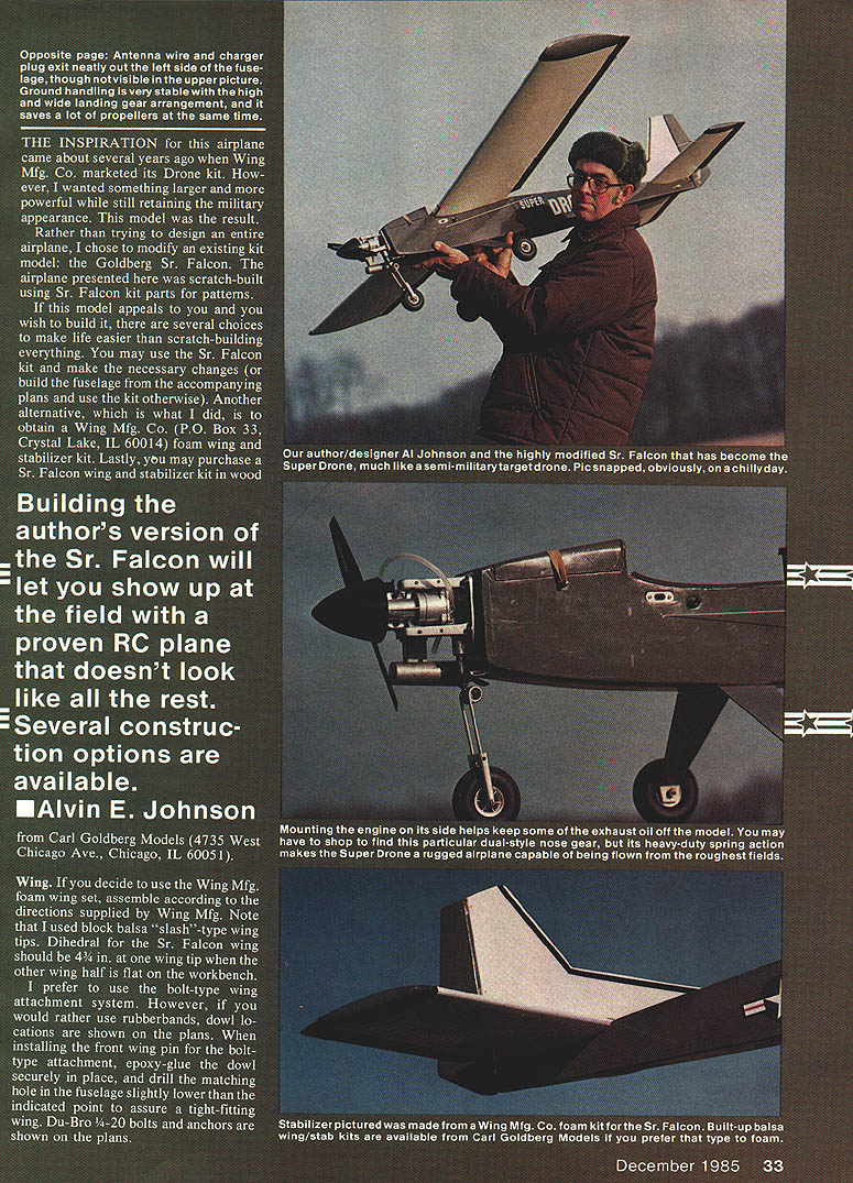
Building this version of the Sr. Falcon lets you show up at the field with a proven RC plane that doesn't look like all the rest. Several construction options are available.
- Alvin E. Johnson
WING
- If you use the Wing Mfg. foam wing set, assemble according to the directions supplied by Wing Mfg.
- I used balsa "slash"-type wingtips.
- Dihedral for the Sr. Falcon wing should be as shown on the plans (set one wing half flat on the bench and measure the dihedral at the opposite tip).
- I prefer a bolt-type wing attachment system. If you prefer rubber bands, dowel locations are shown on the plans.
- For the bolt-type attachment, epoxy the front dowel securely in place and drill the matching hole in the fuselage slightly lower than the indicated point to assure a tight-fitting wing.
- Du-Bro 4-20 bolts and anchors are shown on the plans.
- Make the wing center fairing from balsa plate with a 1/8-ply plate glued where it mates with the fuselage and nose hatch. Carve and sand the fairing to blend with the nose-hatch contour.
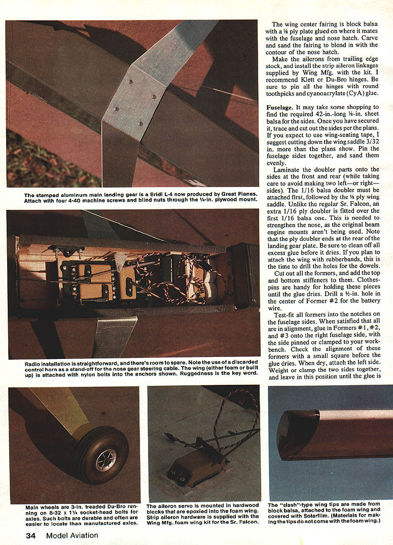
- Make ailerons from trailing-edge stock and install the strip-type aileron linkages supplied in the Wing Mfg. kit. I recommend Klett or Du-Bro hinges; secure pin hinges with round toothpicks and cyanoacrylate (CyA) glue.
- For foam wings, use narrow wood blocks epoxied into the foam for aileron-servo mounts; make balsa root blocks and attach them to the foam wing. Cover with Solarfilm or your choice of covering material. Tips are not included with the foam wing kit.
FUSELAGE
- Obtain the required 42-in.-long sheet balsa for the sides (thickness as indicated on the plans). Trace and cut out the sides per the plans.
- If using wing-seating tape, consider cutting down the wing saddle slightly (about 3/32 in.) more than the plans show.
- Pin the fuselage sides together and sand evenly.
- Laminate doubler parts onto the sides (front and rear). Attach the 1/16-in. balsa doubler first, followed by the wing-saddle doubler (plywood) as shown on the plans. An extra ply doubler over the balsa doubler is used to strengthen the nose because the original beam engine mounts are not being used. Note where the ply doubler ends at the rear landing-gear plate. Clean off excess glue before it dries.
- Cut out all formers and add top and bottom stiffeners. Clothespins are handy for holding pieces until the glue dries.
- Drill a hole in the center of Former #2 for the battery wire (size per the plans).
- Test-fit all formers into the notches on the fuselage sides. When satisfied with alignment, glue Formers #1, #2 and #3 onto the right fuselage side (side pinned or clamped to the workbench). Check alignment with a small square before the glue dries.
- Dry-attach the left side, then weight or clamp the two sides together and leave until the glue is completely dry. When dry, remove the fuselage from the bench, pull the tail-post ends together and glue using clothespins or clamps.
- Install Formers #5, #6 and #7, and glue the tail-post ends together.
- Before adding bottom sheeting, mark the centers of Formers #4, #5, #6 and #7 on the bottom sheet and draw the centerline. Match up the lines when attaching bottom sheeting to help keep the fuselage straight.
- Before gluing the top sheeting, install pushrod guide tubing for the rudder and elevator (use Du-Bro No. 102 control-rod tubing). Glue the top sheeting and be sure to glue the stabilizer in place.
- Install 1/2-in. balsa triangle-stock pieces behind the firewall and above the 1/4-ply landing-gear plate. Glue a small piece of 1/4-ply behind the top of the firewall for extra holding power.
- Cut and carve the nose fairing block and hatch from balsa; blend its contour into the nose hatch. Build the tank hatch from 1/4-in. balsa and consider bolting the top of Former #2 in place for the hatch. The hatch can be held with a rubber band over 4-40 machine screws or with an internal hold-down if preferred.
- Round off all corners on the fuselage by sanding, especially at the front of the firewall. Install servo rails.
FIREWALL AND ENGINE MOUNT
- Gut out the firewall from 1/8-in. aircraft plywood. Laminate the ply doubler onto the back with epoxy; the doubler is full width of the firewall. Scrape epoxy out of the edge groove so the fuselage sides will fit tightly when attached.
- Fit the engine mount to the firewall and drill proper holes. Epoxy the firewall in place and hold with clamps and several No. 64 rubber bands. Good clamps can be made from two 2-in. square maple engine-mount sticks with 6-32 threaded rods and wing nuts placed against the front ends of the fuselage sides; tighten securely with the firewall aligned.
- Allow epoxy to harden overnight before removing clamps. Scrape excess epoxy out of inside corners of the firewall to allow installation of 1/8-in. balsa corner braces later.
- Epoxy-glue in the cross-grained balsa tank-compartment floor and the aircraft-ply landing-gear mount.
- Epoxy the fuselage bottom to the firewall/landing-gear mount.
Engine mounting notes:
- Mounting the engine on its side helps keep some exhaust oil off the model.
- Use socket-head bolts for engine mounting; blind nuts or elastic-stop nuts and washers may be used inside the firewall.
- Muffler fit can be tight; you may need spacers or an exhaust deflector depending on your muffler. A different brand of engine mount may allow easier muffler clearance.
LANDING GEAR
- Main gear: Model Aviation–stamped aluminum main landing gear (Bridi L-4), currently produced by Great Planes, is recommended. Attach with four 4-40 machine screws and blind nuts through the 1/4-in. plywood mount.
- Use 1/4-in. socket-head bolts for wheel axles (steel bolts are durable). Use a plain nut at the wheel and an elastic-stop nut inside the gear. This works well with 3-in. Du-Bro treaded wheels.
- Nose gear: Tatone No. 206S two-leg unit was used on the author's model; alternatives include Fults Tooling Co. gear or a Royal heavy unit. The nose wheel used is a 2-3/4-in. Du-Bro treaded wheel, with steering via a Du-Bro cable.
- The dual-style nose gear with heavy-duty spring action makes the Super Drone rugged and capable of operating from rough fields.
TAIL SURFACES
- The pictured model used a Sr. Falcon foam stabilizer from Wing Mfg. Co., assembled per kit instructions. You may prefer the Goldberg balsa stab or build one from scratch.
- With a foam stab, cut out the required notch for the fin and epoxy the stab to the fuselage, taking care to align it properly. When cured, epoxy a 1/4-in. balsa fin into the notch and add the rudder.
- Make sheet-balsa elevators and rudder, and hinge them to the stab and fin using recommended hinges.
RADIO, TANK AND MISCELLANEOUS
- Radio installation is straightforward — there is room for a spare battery. Use discarded control-horn stand-offs if needed.
- Install pushrod guide tubing before top sheeting (Du-Bro No. 102 tubing for rudder and elevator).
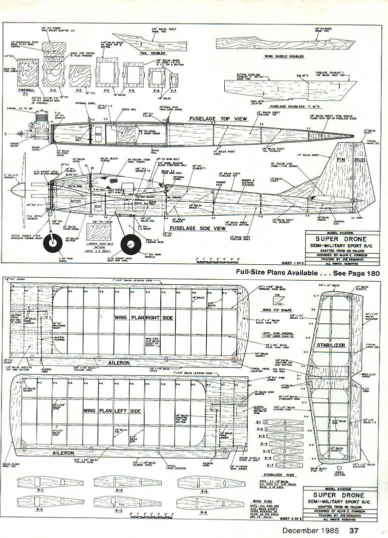
- Fuel tank: I used a Sullivan RST-8 tank. Try to keep the tank level with the engine carburetor. Loosely pack the tank with foam plastic or foam rubber to damp vibration.
- Use 1/4-in. socket-head bolts for landing-gear axles and robust hardware for durability. Use narrow wood blocks epoxied to the foam wing as servo mounts for ailerons.
- Radio nose-gear steering cable can be run to the wing; either foam-built-up wings or nylon-bolt anchors shown on the plans will work.
COVERING AND FINISH
- The author's model used olive-drab MonoKote on the fuselage and white Solarfilm on the wing and stabilizer.
- Lettering on the wings was press-on type purchased locally; Coverite lettering was used on the fuselage.
- Insignia used were from the Wing Mfg. Drone kit; similar insignia are available in MonoKote.
FLYING
- First, balance the Super Drone at the point shown on the plans. The author's model required 3½ oz. of lead under the fuel tank (wrapped in foam rubber); a different engine may alter ballast needs.
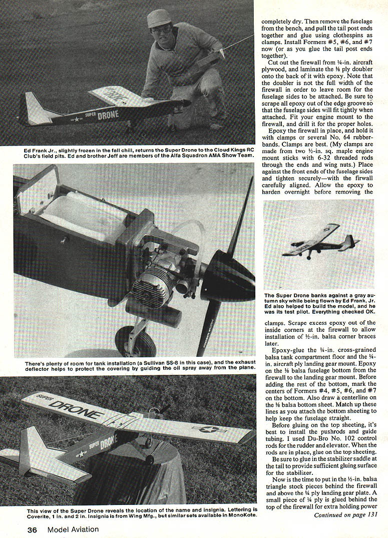
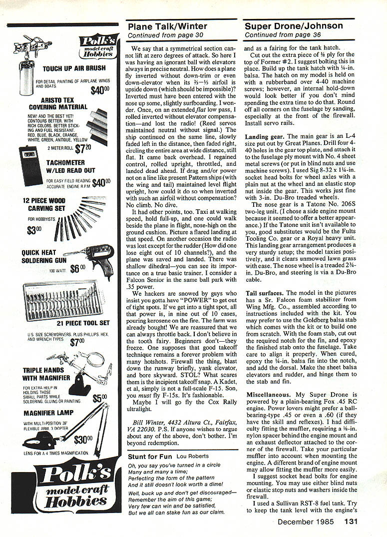
- Since the Super Drone is basically a Sr. Falcon, it flies similarly. The first flights were performed by Ed Frank, Jr., an expert test pilot from the Cloud Kings RC Club. No changes were required to the plane.
Acknowledgments and dedication: I wish to thank Eddie Frank for his help in completing the Super Drone and for serving as test pilot. I dedicate this article to the memory of Eddie's dad, C.S., who succumbed to a heart attack on August 20, 1983. Ed Sr. was an avid RC flier and club officer and is sadly missed.
I would be happy to hear from fellow AMA members who build the Super Drone. Pictures of your versions would be of interest.
Al Johnson 201 Cream Rd., Oxford, PA 19363
Transcribed from original scans by AI. Minor OCR errors may remain.

