
The Super Duper Zilch
ZILCH! What an odd name for a famous model for a series of highly successful kits. Not really, when we recall that a company named S.N.A.F.U. and another, P.D.Q., were contemporaries of the Berkeley Zilch series in the immediate post–WWII era.
Other names were becoming famous in control-line stunt in that era: J.C. "Madman" Yates, Bob Tucker, Davey Slagle, Lou Andrews—and Jim Saftig. These men, and others, were adding dimensions to stunt with their designs and flying skills that seemed incredible. U-Control (a name and mechanism patented and licensed by Jim Walker) stunt had advanced from Ralph Roof's 1946 Nats-winning T-Craft to nearly all the maneuvers flown in the event nearly 30 years later.
I had watched Ralph Roof fly his winning T-Craft in the Wichita Nats, 1946, and was impressed. Having missed the '47 Nats, I was amazed by the quantum jump in flying at the '48 Olathe Nats. In a 24-month period, stunt fliers had made more progress than has occurred in the ensuing 30 years. Although lacking the smooth, highly polished patterns of today, the event had progressed from "doing weird stunts—such as banner pick-ups and wheel rolls" to the beginning of "precision flying."
Vividly etched in my mind is control-line scale at that 1948 Olathe Nats. The models were flown late in the afternoon before a crowd of several thousand spectators. As was so often the case back then, many of the elaborate scale models were too heavy for their spark-ignition engines, barely staggered around the circle, or were unable to clear the ground. Each successful flight of the required ten laps was greeted with enthusiastic applause.
And then it was J.C. "Madman" Yates' turn to fly his lovely Stearman biplane powered with an Orwick 64, finished in white and orange with "Sammy Mason" (on whose full-sized Stearman the model was based) lettered upside down on one side of the fuselage. Yates fired up the Orwick, tuned it to a roar, took off easily and proceeded to do three inside loops, three outside loops, and suddenly was inverted so that Sammy Mason's name was now right side up. The murmur became a roar; we all nearly fell to the concrete in amazement. Truly an astonishing event at the time.
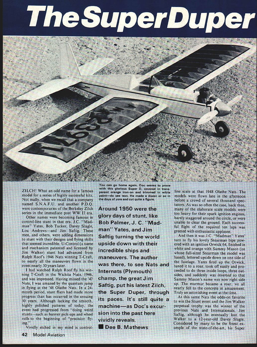
Around 1950 were the glory days of stunt—Bob Palmer, J.C. "Madman" Yates, and Jim Saftig turning the world upside down with their incredible ships and maneuvers. I was there to see Nats and Internats (Plymouth) champ, the great Jim Saftig, put his latest Zilch, the Super Duper, through its paces. It's still quite a machine—as Doc's excursion into the past here vividly reveals.
—Dee B. Mathews
At that same Nats the odds-on favorite to win the stunt event and the Jim Walker perpetual trophy was the winner of the previous Nats and Internationals, Jim Saftig, although he eventually lost the Walker to a 12-year-old Davey Slagle. Considered by many to be the finest example of the state-of-the-art, his Super Duper Zilch was the talk of the contest. His original Super Zilch was being kitted by Berkeley. Saftig's Super Duper was introduced as a kit by Berkeley in the early spring of 1949. The Zilch series was eventually to include seven distinct sizes and degrees of innovation, ranging from a Pee Wee Zilch for .02 power to the Zilch 40 with flaps.
I flew more than a dozen Super Duper Zilchs as a young man, with O&R 60s, Atwood JHs, and with my all-time favorite, the Atwood Triumph 49. Invariably finished in chartreuse and red dope over Silkspan, my Zilchs always flew better than I. They were relatively simple to construct and, in those days of paper routes, clunker cars, and girls, could be scratch-built from a few dollars in materials.
As I dragged out the ancient plans "one more time," several negative memories challenged me to re-engineer Jim Saftig's classic design. Perhaps I tried to gild the lily. The most annoying problem was warped wings. The use of full-length large wood sizes with their built-in stress relief problems had made building an unwarped wing virtually impossible. Such sizes as 3/8" x 2" preformed trailing edges just cannot be purchased in an unwarped state. Equally perplexing was the fuselage construction. A pre-cut bottom sheet was pressed into the assembled sides, while the top was supposedly aligned with a triangular turtle deck. The resultant structure invariably resembled a distressed pretzel and was woefully weak.
The stabilizer was prone to breaking in half occasionally when flying in windy weather. I felt that these problem areas could be alleviated while still retaining the appearance of the original design and improving durability. One visible change is the asymmetrical wing concept introduced on the Veco Warrior in 1950. I had used this modification on several of my later Zilchs so it looks perfectly normal to me. For the purist, the drawings show an alternative equal-span center section.
For authenticity the model should be set up to fly clockwise, as this was the direction of rotation at that time. The advantage of clockwise rotation was the line-tensioning effect of the motor torque. Needless to say I have found considerable amusement, of late, with the introduction of special crankshafts for reverse rotation of the prop to generate what can be had much more simply by flying clockwise. The equal-span wing, when flown counterclockwise, will require at least 3 ounces of lead in the outboard tip.
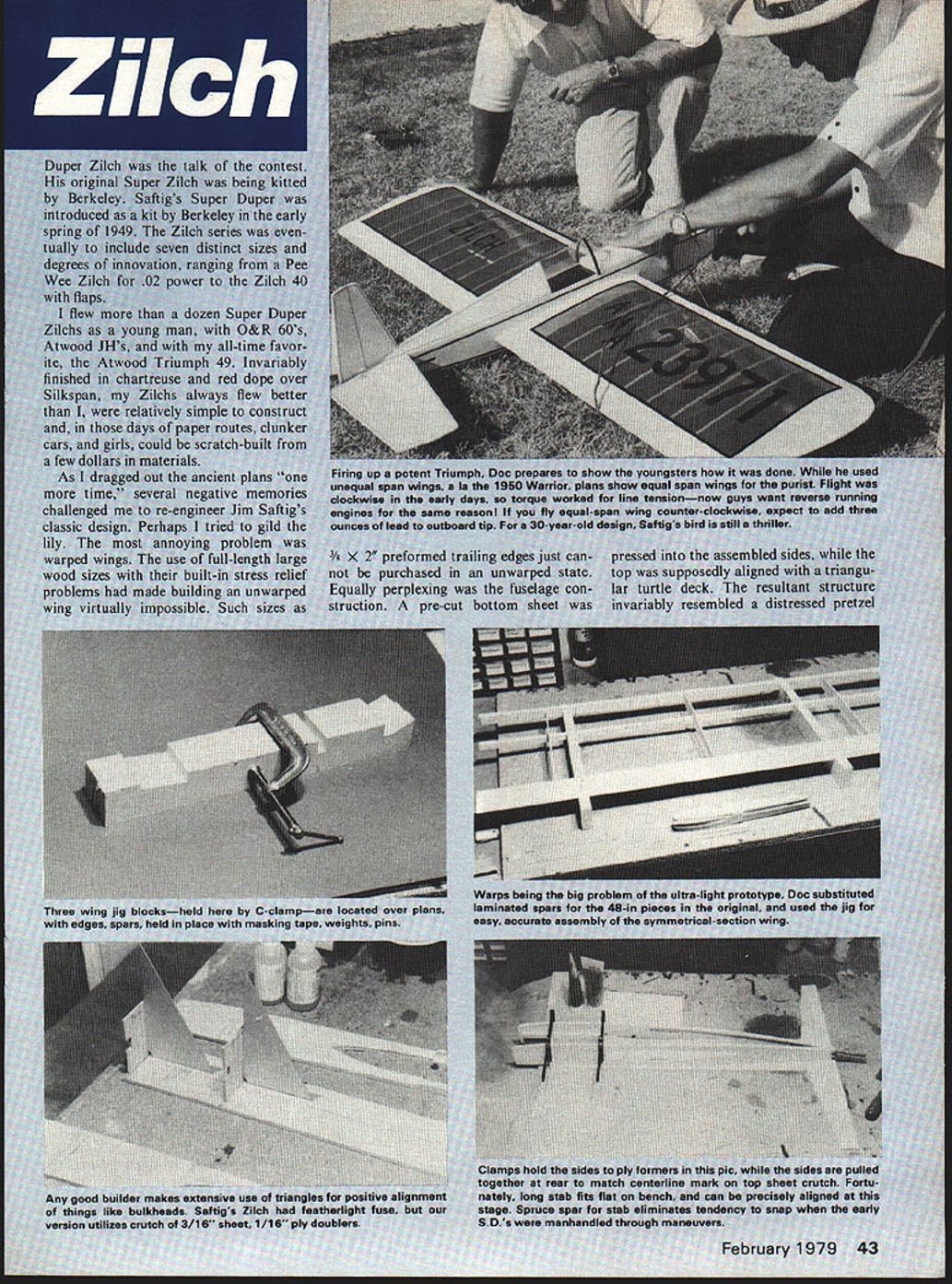
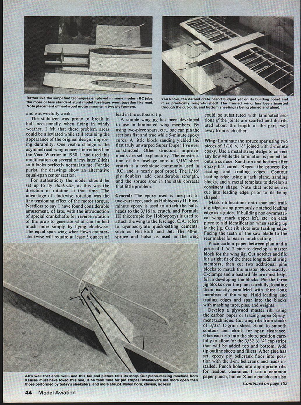
A simple wing jig has been developed to use in laminated wing members. By using two-piece spars, one can pin the sections flat and true while 5-minute epoxy cures. A little block sanding yielded the first truly unwarped Super Duper I've ever constructed. Other structural improvements are self-explanatory. The construction of the fuselage onto a 3/16" sheet crutch is a technique commonly used in R/C and is nearly goof-proof. The 1/16" ply doublers add considerable strength, and the spruce spar in the stabilizer corrects that little problem.
General
The epoxy used is one-part-to-two-part type, such as Hobbypoxy II. Five-minute epoxy is used to attach the bulkheads to the 3/16" crutch, and Formula III thixotropic (by Hobbypoxy) is used to attach the wing to the fuselage. C.A. refers to cyanoacrylate quick-setting cements, such as Hot-Stuff and Jet. The 48-in. spruce and balsa as used in the wing could be substituted with laminated sections if the joints are scarfed and distributed about the length of the part, well away from each other.
Wing
Laminate the spruce spar using two pieces of 3/16" x 1/4", joined with 5-minute epoxy. Use a metal straightedge to correct any bow while the lamination is pinned flat onto a surface. Sand top and bottom after epoxy has cured. Repeat the process for the leading and trailing edges. Contour the leading edge using a jack plane, sanding blocks, and a metal template to develop a consistent shape. Note that notches are cut into the leading edge prior to its being shaped.
Mark rib locations onto spar and trailing edge, using the previously notched leading edge as a guide. If building a non-symmetrical wing, mark "upper," "left," etc., on each piece to aid identification when setting up in the jig. Cut rib slots into the trailing edge. Facing the teeth of the saw blade to the rear makes for easier notch cutting.
Place carbon paper between the plan and a piece of 1 x 2 pine to develop a master block for the wing jig. Cut notches and file for a tight fit of the three longitudinal wing members, then cut two additional pine blocks to match the master block exactly. C-clamps and a bastard file are most helpful in developing the blocks. Pin the three jig blocks over the plans carefully, locating them exactly parallel with the three long members of the wing. Hold leading and trailing edges and spar into the blocks with masking tape, pins, and weights.
Develop a plywood master rib using the carbon-paper or tracing-paper spray-cement technique. Cut wing ribs from stacks of 3/32" C-grain sheet. Sand to smooth contour and check for spar clearance. Glue each rib into the slots, positioning carefully to allow for the 3/32" x 1/4" cap strips that will be added top and bottom. Add tip outline sheets and fillers. After the glue has set, epoxy the plywood bellcrank floor into position with the 3-in. bellcrank and leads installed. Punch holes into appropriate ribs for leadout clearance. I use a common paper punch, but an X-Acto punch can also be used. A punch works most effectively if the rib is backed up with a scrap of 1 x 2 pine to prevent breaking the rib.
Check for absolute free movement of the leadouts and the pushrod; cut and trim until satisfied. Epoxy 1/8" brass tubes to the inside tip, and lead weights to the outside tip. After epoxy cures, remove the wing from the jig. Plank the center section and install cap strips, using C.A. wherever possible. Complete the wing by adding any needed wing-tip contour fillers, and sand to the point of ready-for-covering, but do not cover until the wing is installed into the fuselage.
Tail Feathers
Cut 3/16" balsa to correct length and epoxy the spruce spars to the stabilizer and elevator. Trace outlines onto blanks using carbon paper under the plans, and cut. Sand to airfoil section and add offset to the rudder. Leave the center leading edge of the stabilizer flat for the joint with the fuselage keel.
Fuselage
Trace bulkhead patterns onto plywood using carbon paper under the plans. Note difference in motor-bearer notches for varying powerplants. Use the carbon-paper technique to develop two identical fuselage sides of 1/8" sheet; choose closely matched pieces of wood. Develop the 1/16" ply doublers, using the balsa sides as a pattern. Join to balsa sides with contact cement or 3-minute epoxy.
Mark a midline and the position of the bulkheads onto a straight-grained, flat piece of 3/16" balsa. Attach bulkheads 2 and 3 to the top using 5-minute epoxy. Check for fairness with a 90-degree triangle. Epoxy the stabilizer to the rear of the top, checking that the midlines are parallel.
Epoxy maple motor bearers and fuselage to the bulkheads. Hold in alignment with C-clamps, masking tape, and pins. Allow epoxy to cure, then pull the tailpost together directly over the midline mark and C.A. the fuselage sides to the top crutch.
Slide the wing into the cutout without removing the fuselage from the work surface. Sand and trim sides for clearance as needed. The pushrod stub will slide through with some bending of the 1/8" sides. Measure for equal height of the wing above the work surface and equal distance from the leading edge of the stabilizer. Use Hobbypoxy Thixotropic epoxy to attach the wing in the accessible areas and to bulkhead 3.
Temporarily tape the elevator to the stabilizer with the control horn and C.A. in place. Cut a slot in the fuselage side to clear the heavy-duty pushrod, bending as necessary for clearance. Project the wing pushrod stub in full-up position and join to the rear pushrod with 3/32" I.D. brass tube soldered at the joint.
Mount the previously bent landing-gear wire to bulkhead 1 with nylon landing-gear brackets. Epoxy this assembly onto bulkhead 2 and to the maple bearers. Plank the bottom up to bulkhead 1 using C.A. Sheeting is cross-grained.
Remove the assembly from the work surface. Cut and sand top and bottom to contour. Position the engine on the bearers, mark and drill 9/64" holes for 4-40 T-nuts. Cut and trim nose blocks to clear the engine and attach with 5-minute epoxy.
Cut the hatch inside the bulkheads and sides. Pencil-mark the rear limit of the hatch onto the sides for reference, then glue a 1/2" balsa block in position with the hatch in place. Do not glue the sides or front of the perimeter around the 3/16" hatch—just the removable portion. When glue is dry, cut through the 1/2" sheet using the marks as a guide and remove with a razor saw. Remove the hatch and install hold-down hardware.
Cut bulkhead 4 and turtle-deck sides from firm 1/8" sheet. C.A. bulkhead 4 to the crutch, bevel the joint of the sides for a neat fit to the crutch and C.A. in place. Cut the turtle deck to clear the fin.
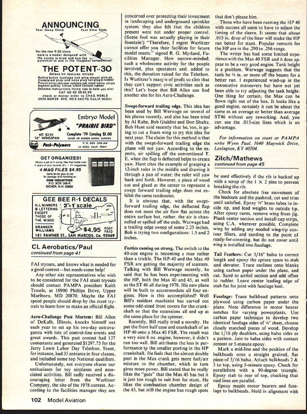
Hinge the elevator to the stabilizer using your preferred method. I used the classic cloth hinges (Sig 1/2" tape) and glue. Permanently attach the horn and clevis, adjusting for neutral and trimming the cutout in the side for free movement.
Trim the turtle deck for a neat fit of the fin; epoxy the fin to the stab and the slot. Check for a right angle with a 90° triangle. Fill any voids in the wing-fuselage joint with Thixotropic epoxy, forming a fillet with a moistened finger. Sand wing and fuselage members.
Finishing
Those wishing authenticity should cover in Silkspan and Testors HEP. If durability and beauty are more important, contemporary finishes are recommended. I covered the wings with transparent MonoKote, masking off the outlines with electrician's tape and newspaper, applying two coats of K&B filler with sanding between coats. The filler was fine-sanded with #380 paper and the whole assembly sprayed with two coats of Perfect White polyurethane paint. Coat tank and engine areas with resin or epoxy for fuel-proofing.
The pinstripes on the prototype are D & J Multi-stripe; the numbers and letters are vinyl stick-on items from an office supply. For those who were not building model airplanes 30 years ago, the spinner is a genuine Fromm (the definitive name in spinners and tanks back then, but long since out of business). The powerplant on the prototype is an Atwood Triumph 49, the last "large-bore" engine to bear the design genius of Bill Atwood.
I have flown the Super Duper Zilch with a Fox 35. Although lacking the brute strength of the Triumph, the Fox is more than adequate to pull the aircraft through the stunt pattern. Maneuvers with models of this era are somewhat different, being more open and abrupt in execution. Inverted flight requires definite up (down, really) elevator, and the horizontal 8s use up a lot of air space. Flight characteristics are delightful with no vicious habits. Grooving is excellent. I did wheel-rolls for my elder son while he was taking photos; he had never seen such a thing. Wheel-rolls were part of the event in the early days.
I hope those of you who choose to construct a new and improved Super Duper receive as much genuine pleasure from yours as I have from mine.
Transcribed from original scans by AI. Minor OCR errors may remain.

