
Super Squire
Larry Windlingland and Cliff Daley
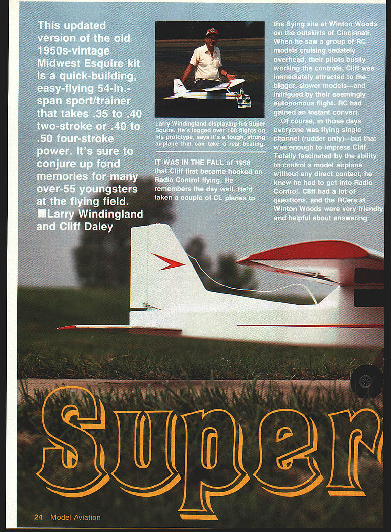
This updated version of the old 1950s-vintage Midwest Esquire kit is a quick-building, easy-flying 54-in. span sport/trainer that takes .35–.40 two-stroke or .40–.53 four-stroke power. It's sure to conjure up fond memories for many over-55 youngsters at the flying field.
In the fall of 1958 Cliff first became hooked on radio-control flying. He remembers the day well: he’d taken a couple of CL planes to the flying site at Winton Woods on the outskirts of Cincinnati. When he saw a group of RC models cruising sedately overhead, their pilots busily working the controls, Cliff was immediately attracted to the bigger, slower models—and intrigued by their seemingly autonomous flight. RC had gained an instant convert.
In those days everyone was flying single-channel (rudder only)—but that was enough to impress Cliff. Totally fascinated by the ability to control a model airplane without any direct contact, he knew he had to get into radio control. The R/Cers at Winton Woods were very friendly and helpful, even to a Control Line flier. The Queen City Radio Control Club recommended the Champ, Trixter Beam, and Midwest Esquire kits.
After looking these suggestions over, Cliff selected the Esquire. Perhaps the model's appearance had something to do with it, or possibly the guys with the Esquires just seemed the most helpful. At any rate, it was with the Esquire kit, a Gyro 22X receiver, the big, hairy Gyro transmitter, and an O.S. .15 engine that Cliff got started in RC.
The Esquire flew well. Over time it took its licks, and somewhere along the way it changed from red-and-white to red-and-yellow. Cliff also built a Li'l Esquire powered by an O.S. .10, and that too was an excellent single-channel performer.
Cliff abandoned radio control flying in the mid-Sixties to try full-scale boating on the Ohio River. By the time he resumed RC activity in 1987 it was digital proportional, multichannel, full-house—everything—a far cry from the Controlaire reed outfits he had used earlier. The Esquire that had survived Cliff's early years lingered in his memory; he had left it with a friend, Jim McConville, in Cincinnati about 25 years earlier.
A call to Jim revealed he was still involved in RC, had a son named Mike who was a "pretty fair" RC pilot—and still had the Esquire. Jim agreed to dig out the old model, put it in flying shape, and have it ready for a big four-stroke fun fly planned for 1988 in Hamilton, Ohio. When Jim inspected the Esquire, though, he realized the ravages of time had left tears in the dope, rib damage, and other issues.
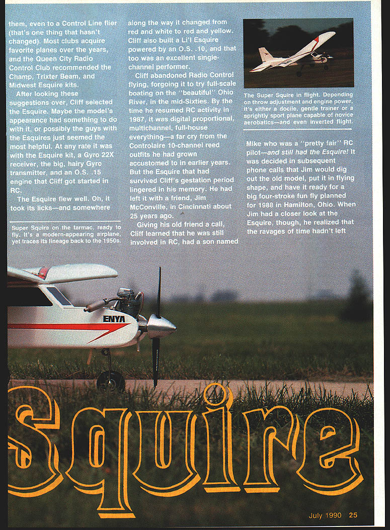
Rather than restore an old, fragile model, Cliff drafted the Super Squire. He decided to have it revamped and built as a flying four-stroke rally/fun-fly model. The first drawings were completed in June 1988, and Cliff test-flew his first prototype in late July. The model is very easy to build and great fun to fly. It performs basic aerobatic maneuvers, takes off smoothly, lands gently, and has outstanding stall characteristics.
The modern-looking Super Squire is adequately powered by a .35–.40 two-cycle engine; a .40–.53 four-cycle is ideal. The hobbyist looking for a simple plane to build from scratch will find it appealing. It’s a good-flying .40 sport/trainer and a great way to update memories of the original Midwest Esquire.
Wing
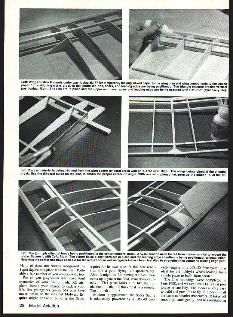
The wing has a flat-bottomed airfoil and uses eighteen identical ribs. Using the rib section shown on the plans as a template, cut ribs out of 3/32-in. balsa. A large opening in the two center ribs for the servo will be cut later. Stack the ribs and final-sand them to a uniform shape. Cut notches for the spars and leading edge with a fine-toothed razor saw.
Following the procedure below, you can make the wing panels without a jig or pins. Remember to make both a right and a left panel.
- Secure the plan to a flat surface with a light coat of 3M 77. Lightly spray the top of the plan and cover it with waxed paper. Give the waxed paper a light coating of 3M 77.
- Place the 1/4 x 1/2-in. balsa bottom spar on the plan, then the 1/4-in.-sq. bottom spar. Position the ribs on the spars, aligning each so that it's perpendicular to the plan. Use the dihedral gauge for the center rib to ensure the correct dihedral angle when the panels are joined.
- Place the 1/4-in.-sq. top spar in the rib slots, then glue the spars to the ribs on both the top and bottom of the wing using Hot Stuff. Hold the 3/8-in.-sq. leading edge in place and glue it to each rib individually. Ensure ribs remain aligned and the leading edge is straight. Glue on the 1/4-in.-sq. trailing edge the same way.
- Carefully remove the panel from the waxed paper and set it aside. Build the other panel using the same method. Don’t forget the small triangular corner braces—they help keep the structures rigid during later steps.
- Align the right and left panels over the plan. Cut a slot in the center ribs at the front edge of the spars for the center dihedral brace, then trial-fit the brace. To set the dihedral, position one panel flat on the building board and elevate the bottom of the outboard rib on the other panel four inches above the board. When properly aligned, glue in the dihedral brace and glue the two center ribs together. Hot Stuff's Special T is suggested for this step to allow some positioning time.
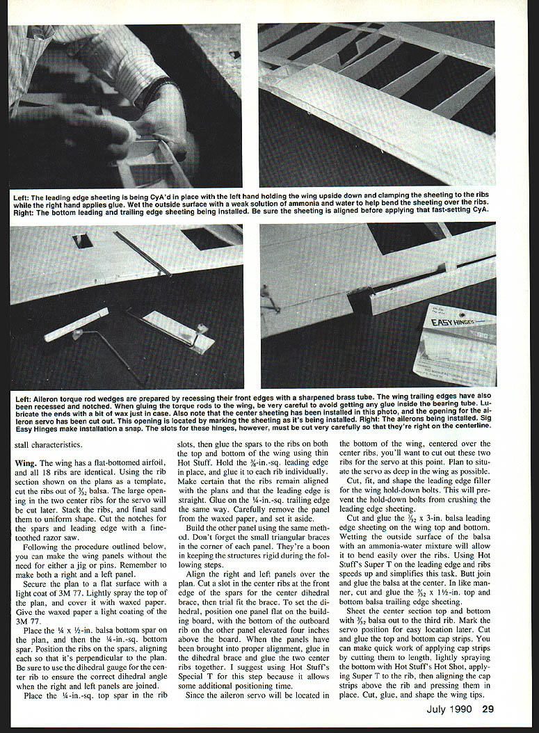
- Since the aileron servo will be located in the bottom of the wing, centered over the center ribs, cut out the two center ribs for the servo now. Plan to situate the servo as deep in the wing as possible. Cut, fit, and shape the leading-edge filler for the wing hold-down bolts to prevent crushing the leading edge sheeting.
- Cut and glue 1/32 x 3-in. balsa leading-edge sheeting on the wing top and bottom. Wetting the outside surface of the balsa with an ammonia-and-water mixture will allow it to bend easily over the ribs. Use Hot Stuff or Super T on the leading edge and ribs to speed this task. Butt-join and glue the balsa at the center.
- Cut and glue 1/32 x 1/2-in. top and bottom balsa trailing-edge sheeting.
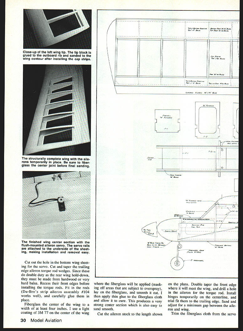
- Sheet the center section top and bottom with 3/32-in. balsa out to the third rib. Mark the servo position for easy location later. Cut and glue the top and bottom cap strips. You can apply cap strips quickly by cutting them to length, lightly spraying the bottom with Hot Shot, applying Super T to the rib, aligning the cap strips, and pressing them in place. Cut, glue, and shape the wing tips.
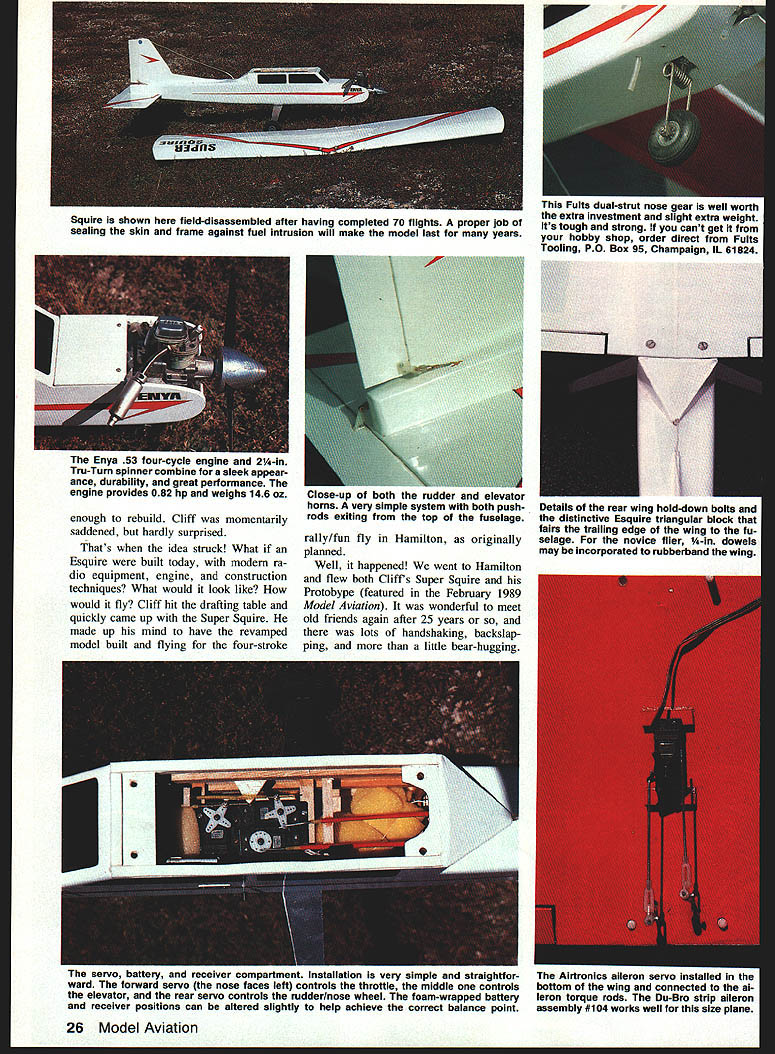
- Cut out the hole in the bottom wing sheeting for the servo. Cut and taper the trailing-edge aileron torque-rod wedges. These wedges double as the rear wing hold-down and must be made from hardwood or very hard balsa. Recess their front edges before installing the torque rods. Fit in the rods (Du-Bro's strip aileron assembly #104 works well), and carefully glue them in place.
- Fiberglass the center of the wing to a width of at least four inches. Apply a light coating of 3M 77 on the center of the wing where the fiberglass will be applied (masking off areas subject to overspray), lay on the fiberglass, smooth it out, and then apply thin glue to the fiberglass cloth and allow it to cure. This produces a very strong center section that is easy to sand smooth.
- Cut the aileron stock to the length shown on the plans. Double-taper the front edge where it will meet the wing, and drill a hole in the aileron for the torque rod. Install hinges temporarily on the centerline and trial-fit to the trailing edge. Sand and adjust for a minimum gap between aileron and wing.
- Trim the fiberglass cloth from the servo area. Cut a hole, then trial-fit the servo and aileron pushrod hardware. Glue small 1/4-in. plywood rails to the underside of the bottom sheeting to accept the servo mounting screws; this helps recess the servo as deeply as possible. Sand the wing leading edges and wing tips to their final shape.
Stall characteristics
The Super Squire stalls benignly and recovers predictably, making it suitable as a trainer. It will perform basic aerobatics, fly inverted reasonably well, and will turn with either aileron or rudder only.
Fuselage
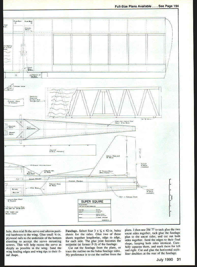
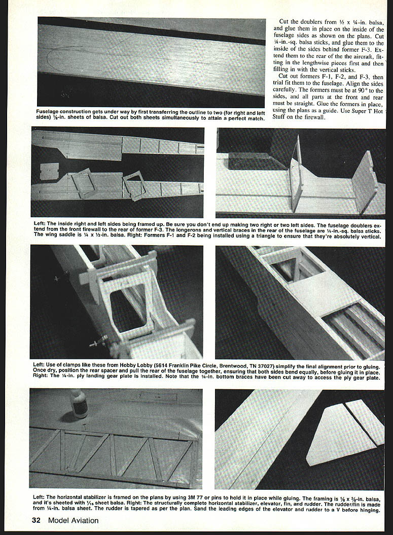
- Select four 3 x 1/8 x 42-in. balsa sheets for the sides. Glue two sheets together lengthwise, edge-to-edge, for each side. The glue joint becomes the midpoint (at former F-3) of the fuselage.
- Cut out the fuselage sides from the plans, or trace the outline onto the glued balsa sides. The recommended method is to tack-glue the uncut sides together with 3M 77, tack-glue the fuselage plan to the uncut sides, and cut out both sides together. Sand the edges to their final shape, keeping both sides identical. Carefully separate them, and mark them left and right.
- Cut the horizontal stabilizer doublers from 1/2 x 1/4-in. balsa and glue them in place on the inside of the fuselage sides as shown on the plans. Cut 1/4-in.-sq. balsa sticks and glue them to the inside of the sides behind former F-3. Extend them to the rear of the aircraft, fitting lengthwise pieces first then filling in with vertical sticks.
- Cut out formers F-1, F-2, and F-3 and trial-fit them to the fuselage. Align the sides carefully; the formers must be at 90° to the sides, and the front and rear parts must be straight. Glue the formers in place using Super T or Hot Stuff on the firewall.
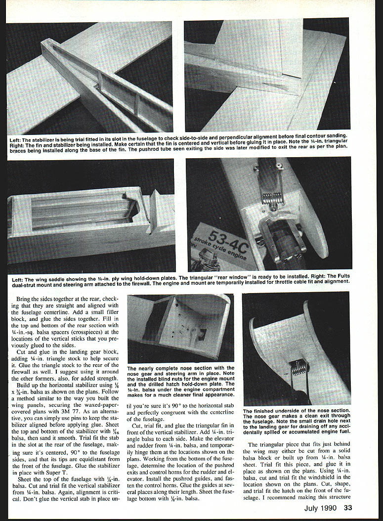
- Bring the sides together at the rear, checking they are straight and aligned with the fuselage centerline. Add a small filler block and glue the sides together. Fill in the top and bottom of the rear section with 1/4-in.-sq. balsa spacers (crosspieces) at the locations of the vertical sticks previously glued to the sides.
- Cut and glue in the landing gear block, adding 1/4-in. triangle stock to help secure it. Glue triangle stock to the rear of the firewall as well and around other formers for added strength.
- Build up the horizontal stabilizer using 1/8 x 3/8-in. balsa as shown on the plans. Use the same waxed-paper method or pins to hold alignment before gluing. Sheet the top and bottom of the stabilizer with 1/16-in. balsa, then sand smooth. Trial-fit the stab in the slot at the rear of the fuselage, making sure it's centered, 90° to the fuselage sides, and that its tips are equidistant from the front of the fuselage. Glue the stabilizer in place with Super T.
- Sheet the top of the fuselage with 1/16-in. balsa. Cut and trial-fit the vertical stabilizer from 1/4-in. balsa. Alignment is critical—do not glue the vertical stab in place until it's 90° to the horizontal stab and perfectly on the fuselage centerline.
- Cut, trial-fit, and glue the triangular fin in front of the vertical stabilizer. Add 1/4-in. triangle balsa to each side. Make the elevator and rudder from 1/4-in. balsa and temporarily hinge them at the locations shown on the plans.
- From the bottom of the fuselage, determine the locations of the pushrod exits and control horns for rudder and elevator. Install pushrod guides and fasten control horns; glue the guides at several places along their length. Sheet the fuselage bottom with 1/16-in. balsa.
- The triangular piece that fits just behind the wing may be cut from a solid balsa block or built up from 1/4-in. balsa sheet. Trial-fit and glue it in place as shown on the plans. Cut and trial-fit the windshield from 1/16-in. balsa. Cut, shape, and trial-fit the removable hatch on the front of the fuselage; one method is shown on the plans. This allows easy access to the fuel tank, batteries, and receiver. The hatch extends from F-1 to the front of the windshield.
Final assembly
- Trial-fit the engine to the engine mount, hold the assembly up to the firewall, and determine engine position and muffler clearance. The Enya .53 four-cycle fits in an upright mounting position. The model requires about 2° each of right thrust and downthrust.
- Mark and drill holes in the firewall for the blind nuts and install them. Temporarily attach the engine mount and engine to the firewall and plan routing for the throttle and nose-wheel steering pushrods.
- Trial-fit an 8-oz. fuel tank and decide fuel-tubing routing. Drill holes for pushrods and fuel tubing. If a remote glow plug device is to be used (highly recommended for the four-cycle Enya due to its glow-plug location), plan its placement now. The authors installed a remote push-button switch and an AA Ni-Cd battery in a single-cell holder wired to the glow plug to eliminate the need for a glow starter at the field.
- Install the 1/4-in. plywood wing hold-down blocks as shown on the plans. (The plans show an option for installing dowels through the fuselage for rubber-band wing hold-down.)
- Trial-fit the wing to the fuselage and check the incidence. The wing should sit at 0° incidence using the horizontal stabilizer as a reference. If you don’t have an incidence meter, measure and set the leading and trailing edges an equal distance from the fuselage centerline. If you cut the fuselage according to the plans, the wing should sit on the cradle at 0° incidence—sand the cradle only if necessary.
- Check that the wing and fuselage are correctly aligned: the wing centered right-to-left and wing tips equidistant from the horizontal stabilizer tips. Pin the wing in place, and drill 3/16-in. pilot holes through the wing and its hold-down blocks where marked on the plans. Remove the wing and redrill the holes for 4-40 nylon bolts. Drill the hold-down block to accept 4-40 blind nuts or tap directly for 4-40 threads.
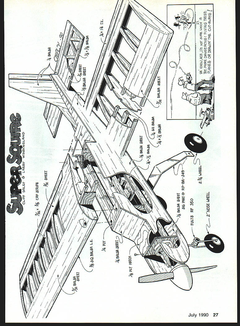
- Attach the main landing gear (aluminum). The authors used Sig part RP-8A-249. It should be 3/4 to 1 in. wide at the fuselage and about 3/8 in. wide at the wheels. They used 2-3/4-in. Dubro wheel hubs, a 2-in. main wheel, and a 2-in. nose wheel. Attach the aluminum landing gear to the fuselage bottom, centered on the 1/4-in. plywood as shown on the plan.
- For steering the authors chose a Fults nose gear (part number RF350). Trial-fit the nose-gear block under the engine, drill holes, and install the gear (you may need to trim the upper portion of the nose-wheel strut for proper fit). If desired, the nose gear can be mounted behind the firewall, though installation and adjustment will be more difficult.
- Cut and fit a piece of 1/4-in. balsa just under the engine at the bottom of the cowl cheeks, extending it forward until flush with the front. Sand to the shape of the cowl cheeks. If you mounted the nose gear inside the firewall, leave a space at the bottom or drill a small hole in the sheeting to serve as a vent for fuel and oil spills. Add a 2-1/4-in. Tru-Turn spinner for looks and durability.
- Check the balance point and determine locations for servos, receiver, battery, switch, and charging jack. Adjust component locations to ensure balance at the indicated point. Install servo rails, tray, and servos, ensuring they will not interfere with wing servos.
- Remove hardware and engine. Brush epoxy or fuelproof dope on the inside of the tank compartment and on the firewall. Sand wing and fuselage to final shape, then recheck balance.
Covering, radio, and engine
Covering
- The prototype was covered with MonoKote, which worked well. Any commercial heat-shrink covering may be used. Choose any trim scheme, though duplicating the original Esquire fuselage trim is suggested to remind over-fifty flyers of the earlier model.
- When covering is complete, reinstall hardware, radio gear, and the engine. Wrap the battery and receiver in generous layers of foam and cradle the fuel tank on foam. Route the antenna through a hole in the triangular block behind the wing and secure the end to the vertical stabilizer. Glue in all hinges, install wing seating tape, and set control throws.
Recommended control throws
- Aileron total throw: 3/4 in.
- Rudder throw: 1-1/2 in.
- Elevator throw: 3/4 in.
Radio
- The Super Squire uses the Airtronics Sport AV6GDR FM radio. Features include servo reversing on all channels and dual rates on elevator and ailerons—useful for first-time fliers. Both transmitter and receiver are rugged and have performed well.
Engine
- The Enya .53 four-cycle was used in the prototype Super Squire. With 0.82 hp and weighing 14.6 oz., the Enya is well suited for this model, providing adequate power for fast takeoffs while idling smoothly for docile landings. Obtain one from your local hobby shop.
Flight performance
This sport/trainer is versatile and tough. Set control surface throws for handling as gentle as desired or coax the model through novice aerobatics. The Super Squire takes well to inverted flight, will turn with aileron or rudder only, and is very rugged. The authors each have over 100 flights on their Super Squires and expect many more. It’s a great “throw it in the car and head for the field” RC airplane.
Super Squire Specifications
- Type of aircraft: Tricycle-gear sport/trainer
- Wingspan: 54 in.
- Wing chord: 11.25 in.
- Total wing area: 607 sq. in.
- Location of wing: Top of fuselage
- Airfoil: Flat-bottomed
- Wing planform: Constant chord
- Fuselage length: 42 in.
- Stabilizer area: 170 sq. in.
- Vertical fin height: 10 in. above fuselage centerline
- Vertical fin width: 9 in. (includes rudder)
- Engine size: .35–.40 two-cycle or .40–.53 four-cycle
- Basic material: Balsa and plywood
- Ready-to-fly weight: 5 to 5-1/2 lb.
- Wing loading: 20.9 oz. per sq. ft.
Bill of Materials
- Two 1/4 x 4 x 36-in. balsa — rudder/stabilizer/elevator
- Four 1/8 x 3 x 36-in. balsa — horizontal stabilizer frame
- Two 1/8 x 3 x 36-in. balsa — horizontal stabilizer sheeting
- Six 1/8 x 3 x 42-in. balsa — fuselage top/bottom
- Ten 1/4 x 1 x 36-in. balsa — spars and fuselage
- Four 1/4 x 1 x 36-in. balsa — spars and fuselage doublers
- Six 1/8 x 3 x 30-in. balsa — ribs, wing sheeting
- One 1/8 x 3/8 x 30-in. balsa — leading edge
- Two 1/4 x 1/4 x 30-in. balsa — aileron (tapered)
- Six 1/16 x 3/8 x 36-in. balsa — cap strips
- Two 1/8 x 1-1/2 x 12-in. balsa — wing tips
- Two 1/4 x 3/8 x 36-in. triangle balsa — bracing
- One 1/8 x 3/8 x 12-in. plywood — F-1, landing-gear brace, wing hold-down
- One 1/8 x 6 x 12-in. plywood — F-2, F-3, hatch, and dihedral brace
Super Squire — Windlingland & Daley
Super Squire kits and distribution: Super Squire is distributed in the United States by Altech Marketing, P.O. Box 286, Fords, NJ 08863 (telephone 1-201/572-5792).
Transcribed from original scans by AI. Minor OCR errors may remain.

