
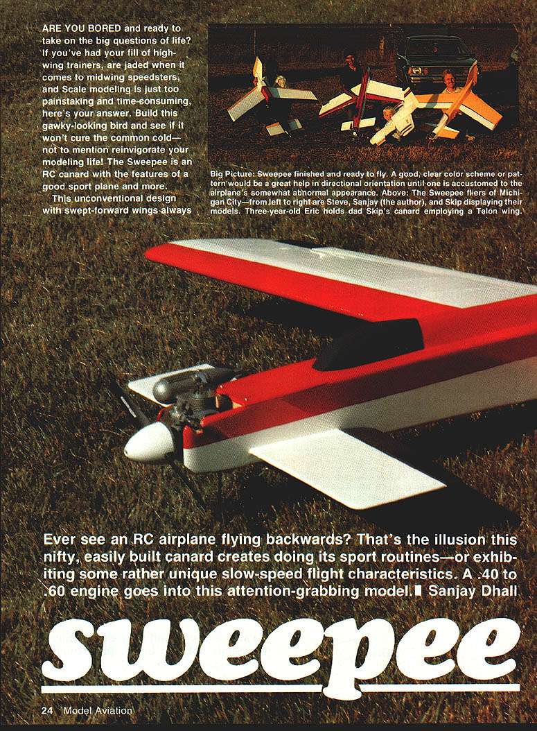
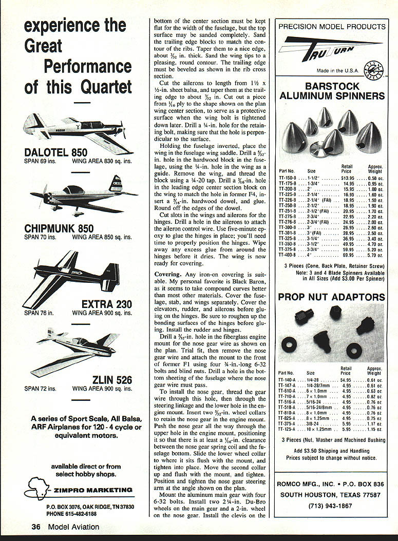

Sweepee
ARE YOU BORED and ready to take on the big questions of life? If you've had your fill of high-wing trainers, are jaded when it comes to midwing speedsters, and scale modeling is just too painstaking and time-consuming, here's your answer. Build this gawky-looking bird and see if it won't cure the common cold—not to mention reinvigorate your modeling life! The Sweepee is an RC canard with the features of a good sport plane and more.
This unconventional design with swept-forward wings—always attention-grabbing—creates an odd illusion in flight. Ever see an RC airplane flying backwards? That's the illusion this nifty, easily built canard creates while doing sport routines or exhibiting some rather unique slow-speed flight characteristics. A .40 to .60 engine goes into this attention-getting model. — Sanjay Dhall
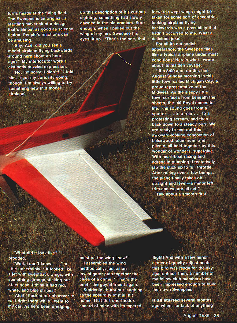
Sweepee turns heads at the flying field.
The Sweepee is an original, a startling maverick of a design that's almost as good as science fiction. People's reactions can be amusing.
"Say, Ace, did you see a model airplane flying backwards around here about an hour ago?" My interlocutor wore a distinctly puzzled expression.
"No, I'm sorry, I didn't!" I told him. It got my curiosity going, though. I'm always willing to try something new in a model airplane.
"What did it look like?" I prodded.
"Well, I don't know . . ." a little uncertainly. "It looked like a jet with sweptback wings, with something strange sticking out of its nose. I think it had red, white, and blue stripes!"
"Aha!" I asked our observer to wait right there while I went to my car. As he'd been dredging up this description of his curious sighting, something had slowly dawned in the old cranium. Sure enough, when I pulled out the wing of my new Sweepee his eyes lit up. "That's the one, that must be the wing I saw!"
I assembled the wing methodically, just as an investigator puts together the clues of a crime. "That's the one!" the guy affirmed again.
Suddenly I burst out laughing as the absurdity of it all hit home. That this unorthodox canard of mine with its tapered, forward-swept wings might be taken for some sort of eccentric-looking airplane flying backwards was a possibility that hadn't occurred to me. What a delicious joke!
For all its outlandish appearance, the Sweepee flies like a typical airplane under most conditions. Here's what I wrote about its maiden voyage:
"It's 8:00 a.m. on this fine August Sunday morning in this little town called Michigan City, a proud representative of the Midwest. As the sleepy little town surfaces from beneath the sheets, the .40 Royal comes to life. The sound goes from a sputter . . . to a roar . . . to a protesting scream, and then back down to a steady purr. We are ready to test out this awkward-looking concoction of balsa wood, aluminum, and plastic, all held together by this wonder of wonders, superglue. With heart-beat racing and adrenalin pumping, I tentatively jab the stick up to full throttle. After rolling over a few bumps, the plane finally takes off straight and level—a minor left trim and we are all set."
Talk about a smooth first flight! And with a few minor center-of-gravity adjustments this bird was ready for the sky again. Since then, a number of my fellow club members have been impressed enough to build their own Sweepees.
It all started several months ago when, for lack of anything better to do, I was reviewing old model airplane magazines. An article by Don Sobbe describing the behavior of forward-swept-wing model airplanes immediately piqued my interest. The concept sounded so new and original that I wanted to see for myself.
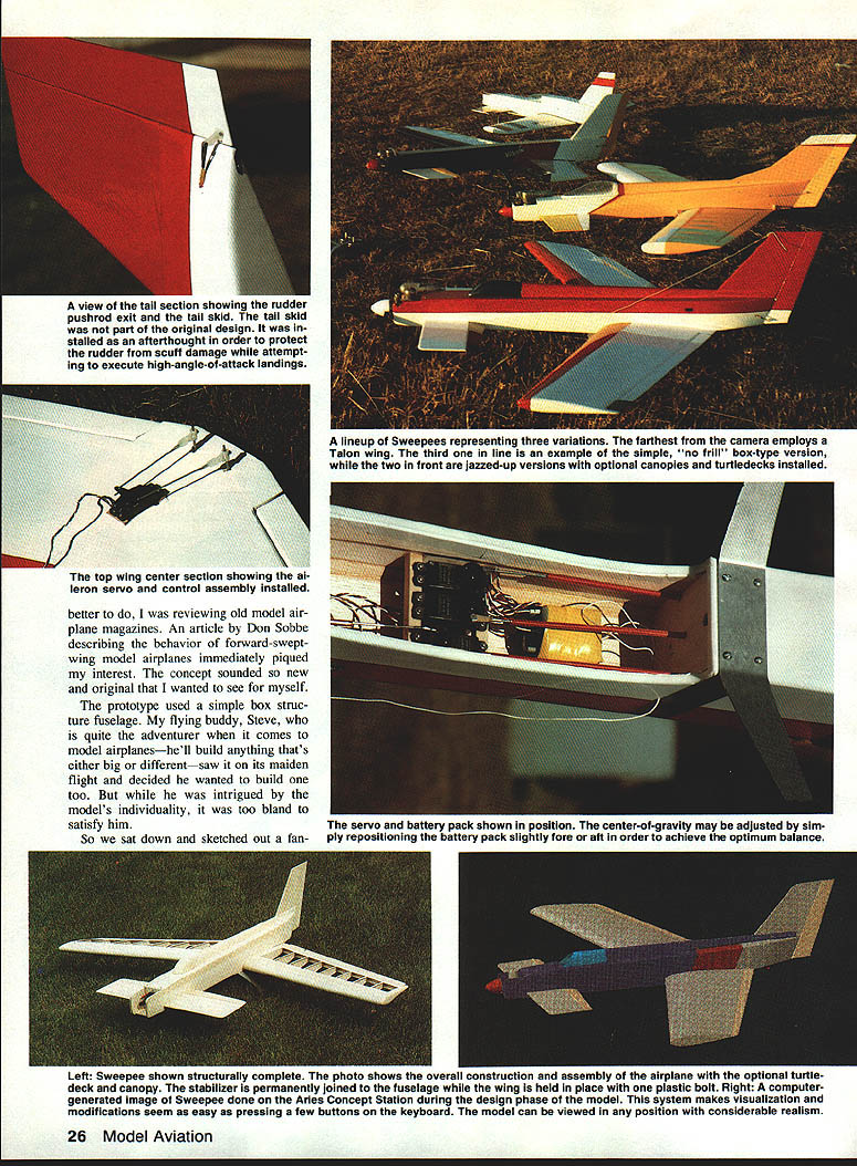
The prototype used a simple box-structure fuselage. My flying buddy, Steve, who is quite the adventurer when it comes to model airplanes—he'll build anything that's either big or different—saw it on its maiden flight and decided he wanted to build one too. But while he was intrigued by the model's individuality, it was too bland to satisfy him.
So we sat down and sketched out a fancier version of the Sweepee. Steve always wants plans to present both options. The major difference is that the turtledeck adorns the deluxe edition; less fastidious Steve just wants to have fun flying. If you want forward-swept wings, you can build the basic box-type fuselage without the turtledeck. There's no noticeable difference in performance between the two versions.
The turtledeck seems to fly just a bit more gracefully; I suspect that's an effect of its added lateral area. Take your pick—the plane flies just like other sport models in normal flying attitudes. It has good high-level control, good roll and pitch (up–down) control, and is a little less sensitive than the usual conventional model. It will perform sport maneuvers—loops, rolls, and combinations.
The real differences between the Sweepee and conventional models don't show up until you slow the airplane down and increase the angle of attack. At that point the model can easily stall with almost zero forward speed. I often experiment by cutting the throttle down a little above idle to observe the effects of the forward sweep. Sometimes the model will just hang, zombie-like.
My favorite maneuver, which I call the instant turnaround, is a zero-radius turn: bring the plane screaming in, cut the throttle, bleed off speed using a gradually increasing amount of up control. Applying the slightest amount of left rudder causes the plane to yaw about itself on a vertical axis. Gradually correcting the turn and applying increased throttle and a little down elevator, I complete the turn and head away again.
Landings can be a lot of fun, too, and you can vary them a little each time. I personally prefer what Steve calls "the hover landings." I bring the plane down to about 100 ft. altitude, cut the throttle, and apply an ever-increasing amount of up control to maintain about a 15° nose-up attitude as the speed drops off. The plane then begins to sink quite rapidly, at about the same speed as its forward velocity. Just before contacting the ground, I apply a little throttle to slow the descent and gain a little forward speed for a light touchdown.
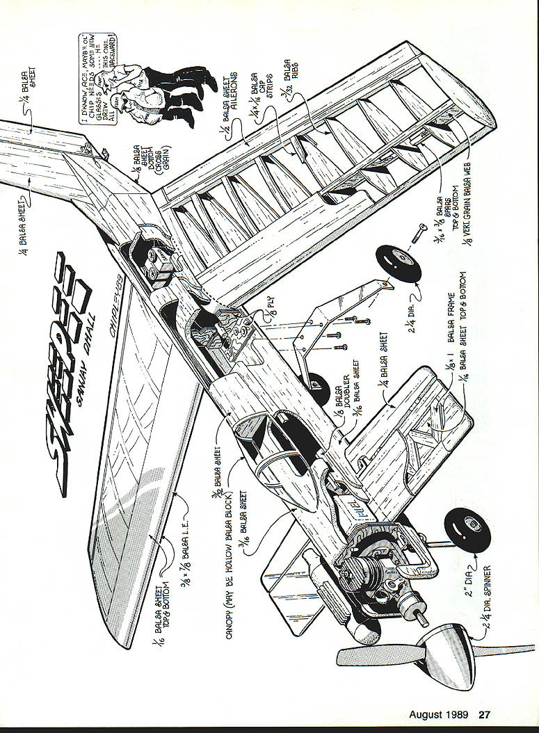
Construction
Though building the Sweepee is relatively straightforward overall, there are a few things that must be done a little differently. Some steps in stabilizer construction are intertwined with construction of the fuselage, and vice versa. For example, the elevator control must be mounted before the fuselage is fully sheeted.
Use whatever type of glue you prefer. I use the Jet brand of medium-viscosity cyanoacrylate glue (CYA) in nearly all my building, relying on epoxy occasionally where I think necessary.
Stabilizer
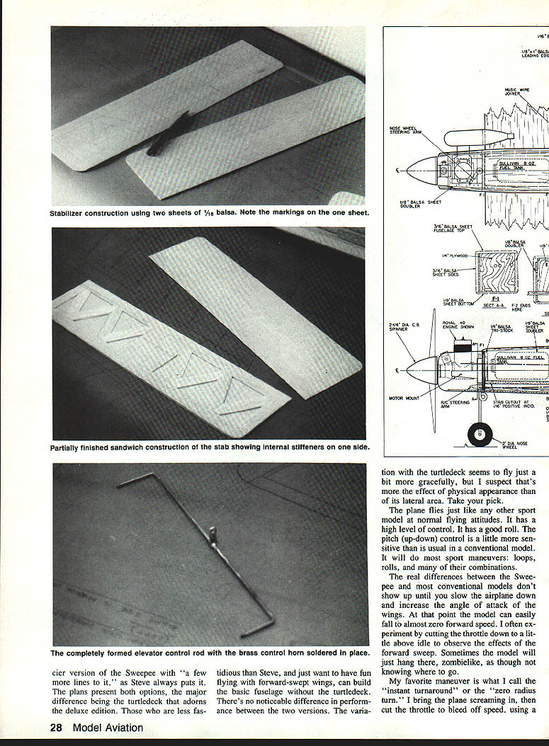
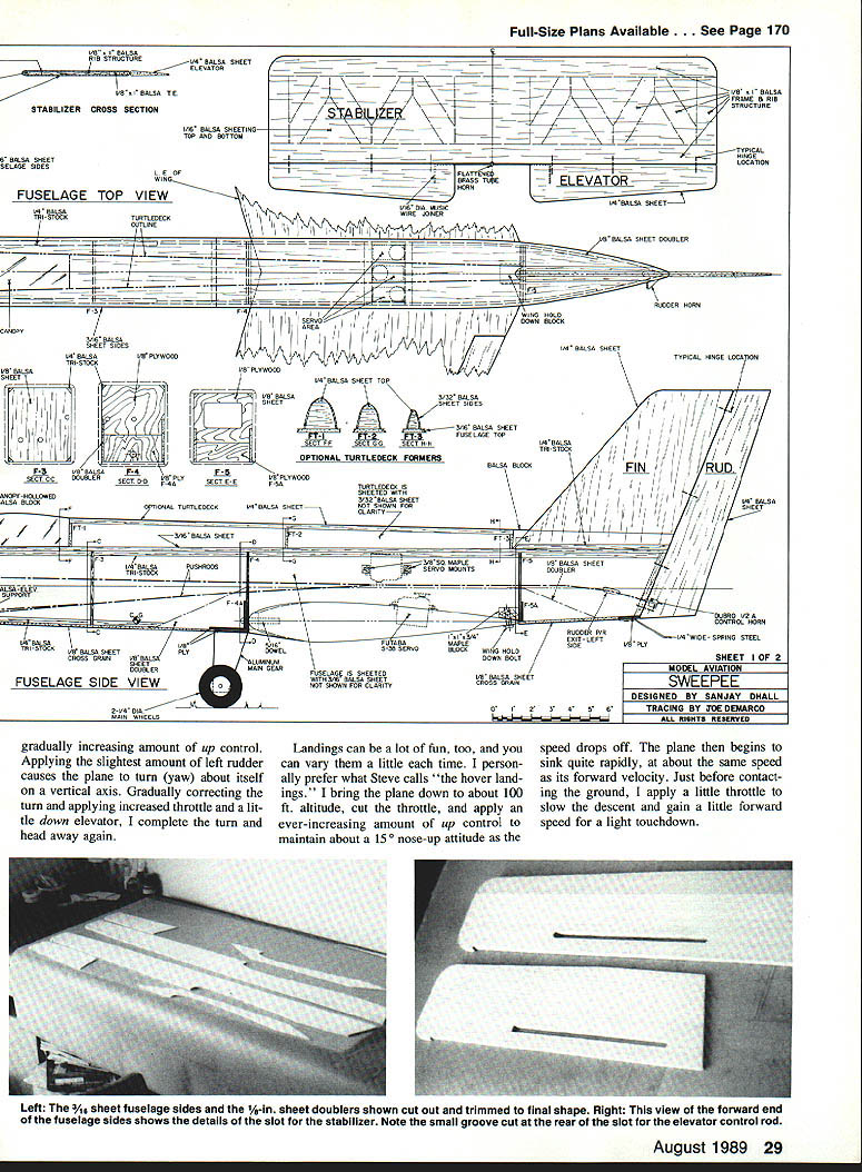
- Cut two sheets of 1/16-in. balsa to the outline of the stabilizer on the plans. On one of the sheets, trace the positions of the 1/8-in. sheet internal stiffeners.
- Pin the marked balsa sheet onto the building board and build directly upon it, using 1-in.-wide strips of 1/8-in. sheet. Add the tips and the 1/8-in. sheet center section.
- Add the top sheeting. Be sure to glue the top sheeting to all the edges, the stiffeners, and the center section. This is important, since, as in most canards, the Sweepee's stab accounts for a greater percentage of the total weight of the airplane than in conventional designs.
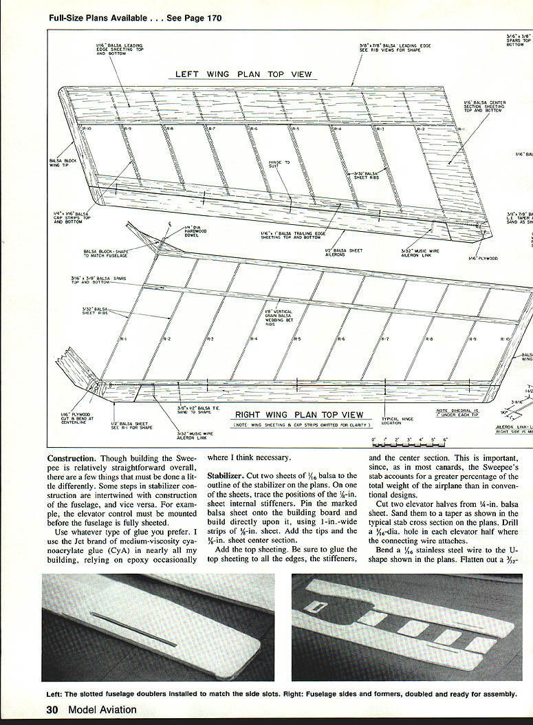
- Cut two elevator halves from 1/8-in. balsa sheet. Sand them to a taper as shown in the typical stab cross section on the plans. Drill a 1/16-in. hole in each elevator half where the connecting wire attaches.
- Rest the wire flat on the board and, holding the control horn vertical, solder the joint between the two. Sand the wire at the joint before soldering to ensure a solid connection.
- Make a small notch at the centerline on the trailing edge of the stab so that the brass control horn can move freely when assembled. Sand the stab edges all around to a nice rounded section as shown in the plan stab cross section. Bevel and round the trailing edge.
Fuselage
- Cut out the fuselage sides from 3/16-in. sheet balsa. Cut out the two side doublers for the nose area and the wing saddle from 1/8-in. sheet. Note that there is a 1/16-in. sq. notch at the aft end of the slot for seating the elevator control wire.
- Add 1/4-in. triangular strips to all edges of the fuselage up to the trailing edge of the wing saddle. Cut out former F1 from 1/4-in. ply (laminating two 1/8-in. ply sheets will work). Drill three holes—one for the throttle pushrod and two for the fuel hoses. Cut a slot for the nose gear pushrod as shown on the plan.
- Cut out former F2 from 1/8-in. ply. Note that when glued in position, this former doesn't extend all the way to the bottom of the fuselage but terminates near the trailing edge of the stab.
- Cut former F3 from 1/8-in. balsa. Cut formers F4 and F4A from 1/8-in. ply. Glue them together, and drill a 3/8-in. dia. hole for the wing dowel.
- Cut out F5 and F5A from 1/8-in. ply. Glue them together, and bevel the side edges at an angle to match the fuselage contour when assembled.
- Bevel the inner sides of the fuselage at the extreme rear edge where the two sides will join, and sand this area down to 1/8-in. Glue in the brass tube, and cut and file it to the shape shown in the fuselage side view. Drill two 1/16-in. dia. holes in the tube as per the plans.
- Slide the U-shaped control wire through one of the holes in the control horn, making sure the horn is at the exact center of the wire. Rest the wire flat on the board and, holding the control horn vertical, solder the joint between the two. Sand the wire at the joint before soldering to ensure a solid connection.
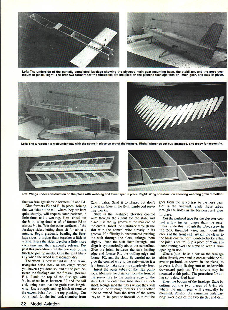
- Glue the two fuselage sides to formers F3 and F4. Glue formers F2 and F1 in place.
- Joining the two sides at the tail, where they are bent quite sharply, will require some patience, a little time, and a wet rag. Chisel out the 3/16-in. wing doubler aft of former F5 to almost 1/32 in. Wet the outer surfaces of the fuselage sides, let them sit for about a minute, then gradually bend the sides together a little at a time until the two ends join. Glue the joint liberally when the wood is reasonably dry.
- Add 1/4-in. triangular balsa stock on the edges you haven't yet done so, and at the joint between the fuselage and the firewall (former F1). Plank the top of the fuselage with 3/16-in. sheet balsa between F2 and the tail end, making sure the grain runs lengthwise. Use a rough sanding block to remove excess balsa from the top planking.
- Cut out a hatch for the fuel tank chamber from 3/16-in. balsa. Sand it to shape, but don't glue it in. Glue in the 3/8-in. hardwood servo tray blocks.
- Slide in the U-shaped elevator control wire through the cutout for the stab and place it in the 1/16-in. groove at the rear end of the cutout. Insert the stabilizer through the slot with the control wire already in its groove. If difficulty is encountered pushing the stab through the slots, enlarge them slightly. Push the stab clear through and align it symmetrically about the centerline. Glue the joints between the stab leading edge and former F1, the trailing edge and former F2, and the slots. Be careful not to glue the control wire to the stab—move it a few times to make sure it's completely free.
- Insert the outer tubes of the flex pushrods. Measure the distance from the front of the servo tray to the trailing edge of the stab. Cut the outer flex tube about an inch short. Rough-sand the tubes where they will attach to the fuselage formers. Cut another tube to extend from the servo tray to 1/2 in. past the firewall. A third tube goes from the servo tray to the nose gear slot in the firewall. Slide these tubes through the holes in the formers and glue in place.
- Cut the pushrod tube for the elevator control a few inches longer than the outer tubes. Slide the pushrod through the tube, screw in the 2-56 threaded wire, and mount the clevis at the front end. Attach the clevis to the brass control horn, double-checking that the joint is secure. Slip a piece of 1/4-in. silicone tubing over the clevis to keep it from opening in use.
- Glue a 3/8-in. balsa block on the fuselage sides directly over and in contact with the elevator pushrod, as shown in the plans, to prevent it from flexing into an undesirable downward position.
- The servos may be mounted at this point. Sheet the bottom of the fuselage. Start by cutting two pieces of 1/8-in. ply where the main gear will mount. Position the aluminum undercarriage over each of the two sheets and drill holes for the 4-40 screws. Remove the undercarriage and glue the plywood in place. When the glue is dry, install the aluminum gear and mount the wheels. Glue the bottom sheeting to the fuselage sides and formers, trimming to fit as necessary. Round off the nose and sand smooth.
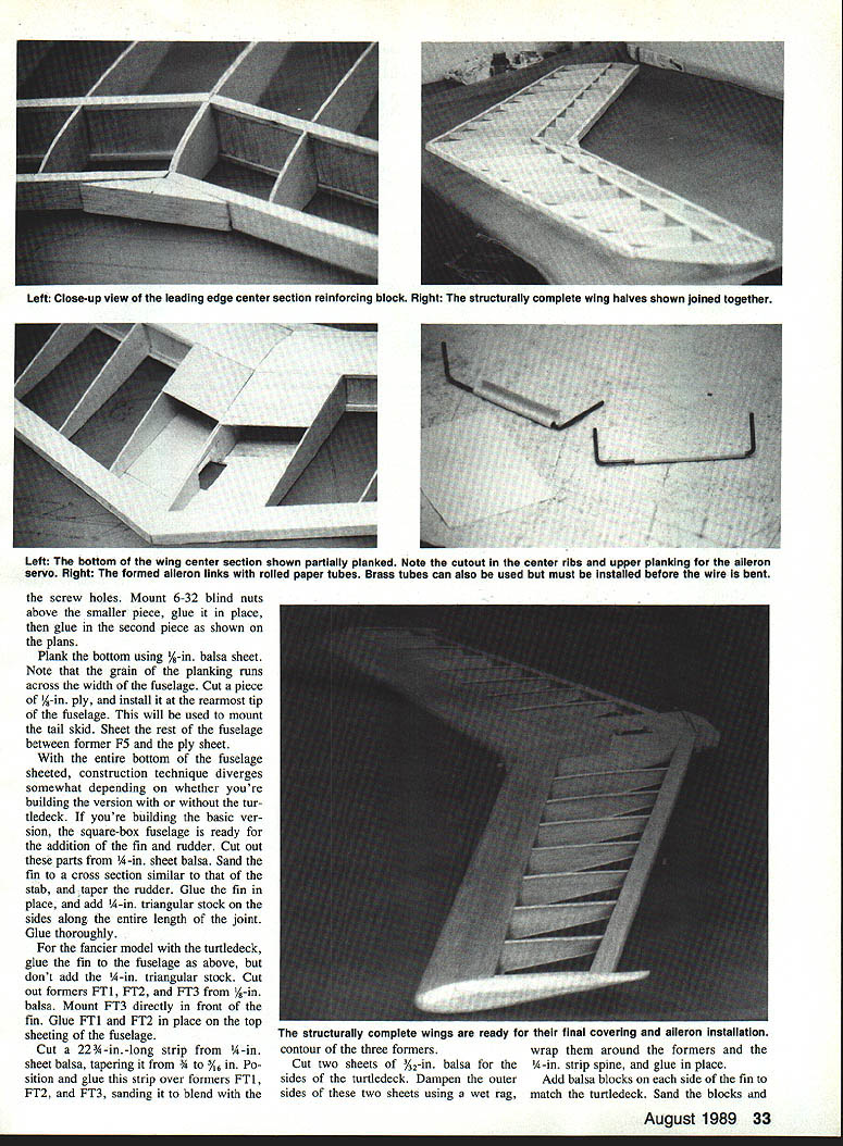
Build the turtledeck by gluing the planked balsa tops to the former assembly. The turtledeck spine is a 1/4-in. square balsa strip glued on top of the formers. Shape the turtledeck to conform to the fin and fuselage lines, then sand smooth.
Assemble the wings on the plans, pinning the spars and ribs in place. Glue the ribs to the spars and webbing. When dry, remove the wing from the plans and add the leading and trailing edges. Joins in the spars should be made over a rib and reinforced with a small piece of plywood. Sand the completed wings to shape, and install the aileron servos and control horns as shown.
- Drill the screw holes for the hinge blocks. Mount 6-32 blind nuts above the smaller piece, glue it in place, then glue in the second piece as shown on the plans.
- Plank the bottom using 5/64-in. balsa sheet. Note that the grain of the planking runs across the width of the fuselage. Cut a piece of 1/8-in. ply and install it at the rearmost tip of the fuselage. This will be used to mount the tail skid. Sheet the rest of the fuselage between former F5 and the ply sheet.
- With the entire bottom of the fuselage sheeted, construction technique diverges depending on whether you're building the version with or without the turtledeck.
If building the basic version (box fuselage):
- The square-box fuselage is ready for the addition of the fin and rudder. Cut out these parts from 1/8-in. sheet balsa. Sand the fin to a cross section similar to that of the stab, and taper the rudder. Glue the fin in place, and add 1/4-in. triangular stock on the sides along the entire length of the joint. Glue thoroughly.
If building the turtledeck version:
- Glue the fin to the fuselage as above, but don't add the 1/4-in. triangular stock. Cut out formers FT1, FT2, and FT3 from 1/8-in. balsa. Mount FT3 directly in front of the fin. Glue FT1 and FT2 in place on the top sheeting of the fuselage.
- Cut a 2 3/4-in.-long strip from 1/4-in. sheet balsa, tapering it from 3/8 to 5/16 in. Position and glue this strip over formers FT1, FT2, and FT3, sanding it to blend with the contour of the three formers.
- Cut two sheets of 3/32-in. balsa for the sides of the turtledeck. Dampen the outer sides of these two sheets using a wet rag, wrap them around the formers and the 1/4-in. strip spine, and glue in place.
- Add balsa blocks on each side of the fin to match the turtledeck and sand to shape. Glue the 3/32-in. planking to the cross sections shown on the plans. Carve out a balsa block canopy—or use a plastic canopy if you can find one to match the cross section. Glue the canopy in front of the turtledeck, sanding or fitting it till it's flush.
Wing
- Cut two sets of wing ribs R1 to R10 from 3/32-in. sheet balsa. Pin down the 1/8 x 3/8-in. balsa main spar directly over the plans for the right wing. Mount and lightly glue ribs R2 through R10 to the bottom main spar.
- The leading edge, grooves for the spars, and trailing edge must all be beveled at about 20° so that the edges line up correctly with the leading edge, spars, and trailing edge to achieve the correct angle of forward sweep.
- Cut out balsa webbings from 3/32-in. sheet—two webbings of each size, for corresponding positions on the right and left wing. The webbing goes between the spars and the grain must be vertical. The vertical dimension of the webbing at any rib can be measured from the rib patterns on the plans. There is a slight taper in the webs as they extend toward the wing tip.
- The webbing between ribs R1 and R2 must be angled so that rib R1 may be tilted slightly to achieve a 1½° dihedral under each wing tip. Mount rib R1 at the appropriate angle. Glue the top spar and push it into place so that it rests in the rib slots and over the webbings. Glue the spar to the ribs and the webbings.
- Cut out the leading and trailing edges from 3/8-in. sheet balsa. Both are slightly tapered: the leading edge tapers from 3/8 in. at the root to 1/4 in. at the tip, while the trailing edge tapers from 1/2 in. at the root to 1/16 in. at the tip. Rest the leading edge (not sanded to shape yet) on scrap balsa to align it. The ribs should be positioned so that the leading and trailing edges are at the same height for every rib—this helps ensure a warp-free wing.
- Glue the leading and trailing edges into place and reinforce all joints. When dry, lift the wing off the board. Glue in the hinges on the top and bottom of the trailing edge as shown on the plans. Glue the 3-in.-wide 1/16-in. planking between the ribs where indicated on the plans.
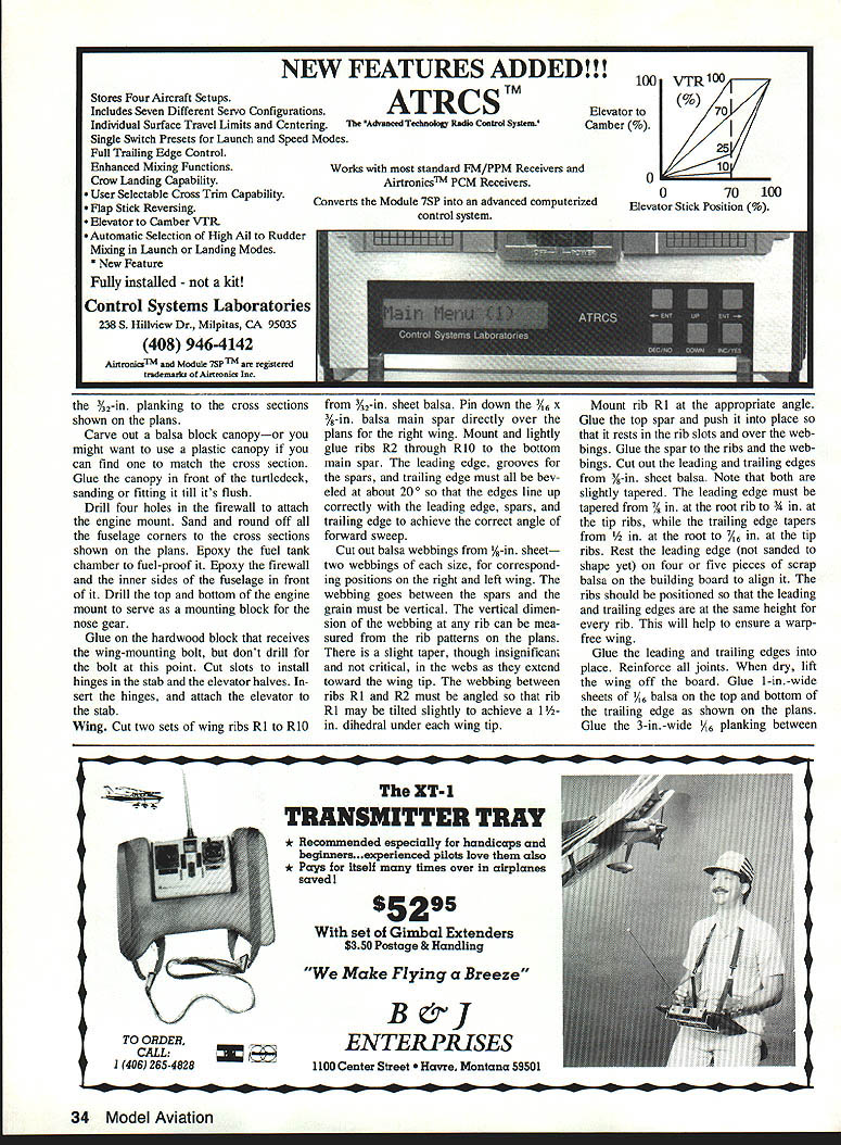
- Build the other half of the wing following the same general procedure. Sand off excess planking from the center section. Join the two wing halves together at rib R1. Cut out slots for the wing servo in the joined R1 ribs.
- Sheet the center section between ribs R1 and R2 on both sides of the wing, top and bottom, with 1/8-in. sheet balsa. Cut an opening in the top planking for the aileron servo directly over the slots in ribs R1. The servo rails consist of two 1-in.-long by 3/8-in.-wide strips of 1/8-in. ply positioned at the front and back ends of this opening.
- Keeping the ribs centered, glue 1/16 x 1/4-in. cap strips over all the remaining ribs, top and bottom, from the spar to the trailing edge. Cut two wing tip blocks from 3/4-in. balsa, using the outer wing cross section at rib R10 as a pattern (two laminations of 3/8-in. sheeting will also work). Glue the tip blocks to the wing tips.
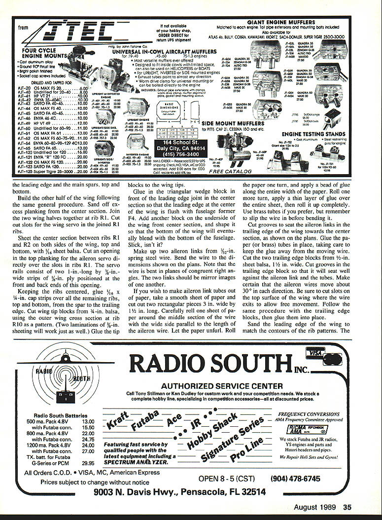
- Glue in the triangular wedge block in front of the leading edge joint in the center section so that the leading edge at the center of the wing is flush with fuselage former F4. Add another block on the underside of the wing front center section and shape it so that the bottom of the wing will eventually blend with the bottom of the fuselage.
- Make up two aileron links from 3/32-in. spring steel wire. Bend the wire to the dimensions shown on the plans; the wire is bent in a plane of congruent right angles. The two links should be mirror images of one another.
- If you wish to make aileron link tubes out of paper, cut two rectangular pieces 3 in. wide by 1½ in. long. Carefully roll one sheet of paper around the middle section of the wire with the wide side parallel to the length of the aileron wire. Let the paper unfurl, roll the paper one turn, and apply a bead of glue along the entire width of the paper. Roll one more turn, apply a thin layer of glue over the entire sheet, then roll it up completely. Use brass tubes if you prefer, but remember to slip the wire in before bending it.
- Cut grooves to seat the aileron links in the trailing edge of the wing toward the center section, as shown on the plans. Glue the paper (or brass) tubes in place, taking care to keep the glue away from the moving wire.
- Cut the two trailing edge blocks from 1/2-in. sheet balsa, 1½ in. wide. Cut grooves in the trailing edge block so that it will seat well against the aileron inner and the tubes. Make certain that the aileron wires move about 30° in each direction. Be sure to cut slots on the top surface of the wing where the wire exits to allow free movement. Follow the same procedure with the trailing edge blocks, then glue them into place.
- Sand the leading edge of the wing to match the contours of the rib patterns. The bottom of the center section must be kept flat for the width of the fuselage, but the top surface may be sanded completely. Sand the trailing edge blocks to match the contour of the ribs. Taper them to a nice edge, about 3/32 in. thick. Sand the wing tips to a pleasing, round contour. The trailing edge must be beveled as shown in the rib cross section.
- Cut the ailerons to length from 1½ x 1/2-in. sheet balsa, and taper them at the trailing edge to about 3/32 in. Cut out a piece from 1/8 ply to the shape shown on the plan wing center section to serve as a protective surface when the wing bolt is tightened later. Drill a 1/4-in. hole for the retaining bolt, making sure the hole is perpendicular to the surface.
- Holding the fuselage inverted, place the wing in the fuselage wing saddle. Drill a 3/32-in. hole in the hardwood block in the fuselage, using the 1/4-in. hole in the wing as a guide. Remove the wing, and thread the block using a 1/4-20 tap. Drill a 7/64-in. hole in the leading edge center section block on the wing to match the hole in former F4, insert a 5/16-in. hardwood dowel, and glue. Round off the edges of the dowel.
- Cut slots in the wings and ailerons for the hinges. Drill a hole in the ailerons to attach the aileron control wire. Use five-minute epoxy to glue the hinges in place; you'll need time to properly position the hinges. Wipe away any excess glue from around the hinges before it dries. The wing is now ready for covering.
Covering
- Any iron-on covering is suitable. The author prefers Black Baron, as it seems to take compound curves better than most other materials.
- Cover the fuselage, stab, and wings separately. Cover the elevators, rudder, and ailerons before gluing on the hinges. Be sure to roughen up the bonding surfaces of the hinges before gluing. Install the rudder and hinges.
Hardware and Final Assembly
- Drill a 5/32-in. hole in the fiberglass engine mount for the nose gear, as shown on the plan. Trial fit, then remove the nose gear wire and attach the mount to the front of former F1 using four 3/8-in.-long 6-32 bolts and blind nuts. Drill a hole in the bottom sheeting of the fuselage where the nose gear wire must pass.
- To install the nose gear, thread the gear wire through this hole, then through the steering linkage and the lower hole in the engine mount. Insert two 5/32-in. wheel collars to retain the nose gear in the engine mount. Push the nose gear all the way through the upper hole in the engine mount, position it so that there is at least a 1/8-in. clearance between the nose gear spring coil and the fuselage bottom. Slide the lower wheel collar to where it sits flush with the mount and tighten into place. Move the second collar up and flush with the mount, and tighten. Position and tighten the nose gear steering arm at the angle shown on the plan.
- Mount the aluminum main gear with four 6-32 bolts. Install two 2-1/4-in. Du-Bro wheels on the main gear and a 2-in. wheel on the nose gear. Install the clevis on the nose gear pushrod, and connect it to the steering arm. Any adjustments may be made at the servo end of the pushrods.
- Install the three servos on the servo tray. Drill a hole on the left rear of the fuselage as per the plans, at an angle to allow the rudder pushrod to pass through. Cut a strip of thin sheet metal 1/4 in. wide, then bend and drill it to make the tail skid.
- Mount a 1/2A control horn on the side of the rudder as shown on the plan. Connect the pushrods to the servos using standard Futaba servo disks. Trim the elevator pushrod to size before connecting it to the servo. Position the elevator pushrod so that the bottom surface of the elevator is flush with the bottom of the stab in the neutral position. Set the throw of the elevator to about 1/8 in. in either direction. Mount the aileron servo and ensure about 1/4 in. of throw in each direction at the trailing edge of the ailerons.
- Remember: in a canard, elevator directional response is the opposite of that in a conventional model airplane. For the nose to pitch up, the elevator must move down; for the nose to move down, the elevator must move up.
- Drill two holes in the firewall for the fuel lines. Mount a Sullivan 8-oz. fuel tank. Install the 3/16-in. sheet hatch over the fuel compartment, securing it with four small wood screws at the corners.
- Mount the engine on the fiberglass mount using 6-32 bolts. Use a 10 x 6 prop for a .40-size engine. Follow the manufacturer's prop size recommendation for a larger engine. Use a 2-1/4-in. CB spinner.
- Cover the receiver and the battery pack in foam, then store them in the wing saddle area of the fuselage. Appropriately placing the battery pack may be all that's necessary to balance the model at the indicated center-of-gravity. Mount the switch somewhere on the left side of the fuselage to avoid exhaust spray. Mount the wing using a 1/4-20 plastic bolt.
Flying
- If you have the patience, wait for that perfect day and set the Sweepee sailing. If you're eager to see how it flies but the weather isn't terrific, let her loose anyway.
- Before you launch the model, be sure to balance it at the center-of-gravity indicated on the plan — 5-3/4 in. from the leading edge of the wing with an empty tank. If you built the plane according to the plans, adding weight to achieve the balance point shouldn't be necessary. If you need to make an adjustment, relocating the battery pack should be sufficient.
- Use this center-of-gravity position for the first few flights. Should you feel the need to move the center-of-gravity after that, shift it in small increments, say 1/8 in. at a time.
- In most respects the Sweepee flies just like any other model, though it does have a few quirks to remind you of its maverick origins. As you'll probably observe, no matter how much up control you use, the model won't take off until it's ready. The airplane's slow-speed flying characteristics are peculiar.
- When coming out of a near hover, increase the throttle gradually and ease off the elevator stick, even using a little down control to get some extra speed. Try these maneuvers at safe altitudes in the beginning while you're getting used to the airplane's foibles.
- A color scheme that clearly distinguishes the front of the plane from the back should come in handy.
- At low throttle the flight characteristics of the model are similar to any sport airplane until you force a high angle of attack. At slow speeds, gradually increasing the up control seems to have little effect on the airplane's attitude—but does bring the model to a virtual halt. At this point the sink rate will be high, and you probably will have to keep the rudder control active to keep it on course. However, the plane shows relatively little tendency to stall out of this condition.
I'm still exploring the full range of this airplane's flight characteristics. Join me in the search. Discover the Sweepee for yourself — and happy backward flying.
Transcribed from original scans by AI. Minor OCR errors may remain.

