
Swiss World War 2 Fighter
TO THE SWISS, perhaps more than any other nation, war is abhorrent and a phenomenon peculiar to others. Despite their aversion to violence, the Swiss will readily fight to maintain their now traditional neutrality. The Swiss Air Force is unique in that its personnel are militia-civilians for more than 10 months of each year. The terms of the Swiss Confederation expressly forbid the maintenance of regular forces. The Flugwaffe, as the Swiss Air arm is generally known, is a true component of the militia. The tasks of the Flugwaffe have remained virtually unchanged throughout the history of Swiss military aviation, namely, to ensure the integrity of Swiss air space by challenging and, if necessary, destroying any intruder; defending Switzerland from aerial attack, and providing strike and reconnaissance support for Swiss ground forces.
Chuck Felton Photos by Lane Mosby
The Federal Aircraft Factory is the official government establishment which manufactures aircraft for the Swiss Air Force. Most Swiss aircraft have been bought or built under license from other countries. One of its few indigenous designs was the C-3603. As the threat of war in Europe appeared ever more likely to materialize, the Swiss Federal Government revived, in 1938, the C-36 design evolved a few years previously, with a view of providing the Swiss Air Force with more modern ground-attack equipment. The original single-tail C-3600 project remained a design only, but two prototypes with twin tail assemblies were ordered. These differed in powerplants. Both machines had nonretracting undercarriages, and the two-man crew was accommodated in tandem seats beneath an extended canopy. The C-3601 made its maiden flight in the spring of 1939; the C-3602 following in November of the same year.
A thorough test program on these two machines was followed by an order for 160 production aircraft under the designation C-3603. A more powerful model made its appearance with the first flight, on August 21, 1944, of the C-3604, and an order was placed for 100 machines of this type. As things turned out, however, the advent of jet engine fighters caused the Swiss government to curtail orders for the C-3604, and production of this type ceased after only 13 had been completed. Over 30 years later, C-3604s are still serving with the Swiss Air Force. Twenty-two have been converted to turbo‑prop engines for target‑towing duties and designated as the C‑3605 version.
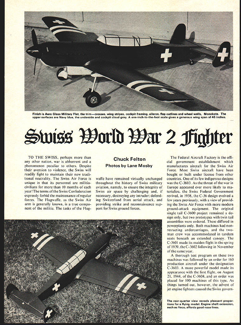
The model is built to a scale of 1" = 1' which gives a wing span of 45 in and a length of 35.5 in. It is quite light for its size and is adequately powered by engines from .29 to .35 size. It was designed for scale sport flying. It was not built for stunt flying, although the model will do a sharp wingover. The flat bottom wing and thick airfoil gives a lot of lift at low speed and prevents the model from sinking like a rock when the engine stops. The landing glide is smooth and stable. The stance of the main landing gear is wide enough to give smooth landings without wing tip scraping. In addition, the long tail‑moment and forward location of the main gear virtually eliminate nosing over on landing. The size of the model allows the engine to be neatly cowled, eliminating a protruding engine cylinder head. The canopy is made of balsa and not plastic for two reasons. First, it is easier for the average modeler to build it of balsa and secondly, few photos are available from which to obtain interior cockpit details. However, I think you will agree that the balsa canopy with its black strip framework presents a neat appearance.
Before I start on the construction phase, I wish to thank Mr. H. Rhomberg of the Swiss Aircraft Factory Technical Department for providing me with a set of 3‑view drawings of the C‑3603 aircraft.
Construction
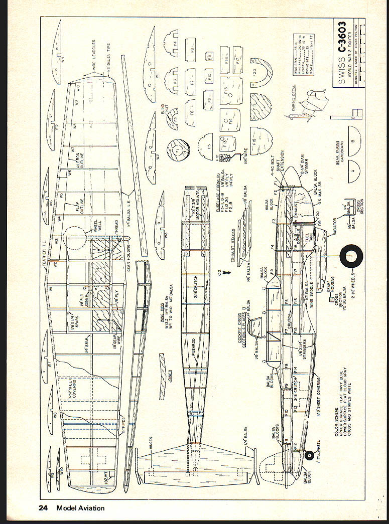
Wing: Cut out all wing ribs. Cut out holes in ribs for the bellcrank leadout wires in left ribs only. Cut out and join the 1/4 in. balsa spars with the 1/8 in. ply joiner with the proper dihedral angle as shown on the wing front view. When dry, glue all ribs to the spars. Add 1/4 x 1/8 in. spars between ribs W1 to W3, both top and bottom. Make two landing gears from 1/16 in. wire from the patterns shown in the wing top view and fuselage side view. Cut out 1/8 in. ply mounting platforms for the landing gear and bellcrank. Attach the landing gear to the platforms with thread. Apply glue to the thread for extra strength. Insert platforms in place in the wing and glue in 1/4 in. sq. balsa supports as shown in the wing front view. Epoxy platforms to the 1/4 in. sq. balsa supports and to the wing ribs. The bellcrank platform is installed in a similar manner. Install a 3 in. Perfect bellcrank and a 3/16 in. wire pushrod. Bellcrank leadouts are made from 1/32 in. wire. Cover bottom of wing with 3/32 in. sheet balsa. Cement a 1‑oz. wing‑tip weight in each tip. No additional article text on this page — it contains the plan drawings, parts templates and labels only.
Swiss WW II Fighter
Fuselage: Begin fuselage by cutting out 3/16 in. balsa crutch in one piece as shown in fuselage top view. Cut out all fuselage formers. Bend 1/16 in. tail-wheel gear as shown and attach to F12 with thread, applying glue to the thread. Pin crutch over plans and glue formers F3 to F11 to the crutch. Add 1/4 x 1/8 in. stringers down top and sides. The hardwood motor mounts are next. Try the following procedure to avoid misalignment problems. Mark and drill the engine mounting holes in each hardwood mount. Install 4-40 blind nuts in each hole on the bottom side of the mount. Slide the mounts into position through formers F3 and F4 and bolt the engine to the mounts. Epoxy the mounts firmly in place. When thoroughly dry, remove the engine and the mounts will be in perfect position. Note that an engine shaft extension, such as Veco brand, is used to move the engine towards the rear of the cowl where there is more room. Keep this in mind when locating the motor mounts.
Choose your fuel tank and install under the motor mounts so that the front end of the tank will be butted up against the back of F19. I used a Veco 4 oz. square wedge tank. The tank was secured with a 1 in. aluminum strap, slipped over the tank fill tube, which is bolted through the sides of the motor mounts with one 4-40 bolt per side. Be sure to attach generous lengths of fuel tubing to each tank vent. Formers F12 through F19 are now glued to the bottom side of the crutch. Add 1/4 x 1/8 in. stringers down the sides and bottom center as shown in side view. Epoxy two 5/16 in. wood dowels down holes through former F19. Test fit the wing in place making sure there is enough room cut out of the aft fuselage formers for the pushrod to operate freely.
Cut wing saddle pieces from 1/8 in. balsa and glue in place. The fuselage is now covered with 1/16 in. sheet balsa. Cut opening in left fuselage side between F10 and F11 for pushrod exit. Add balsa block behind F12 and block under the stabilizer aft of F11. Add balsa block between formers F2 and F3. This block must be hollowed out to fit your engine. Drill a hole on the centerline of F2 as shown and install a 4-40 blind nut on the back side to be used for the cowl attach. Cement F2 to crutch and balsa block.
The cockpit is made entirely of balsa. The ends are balsa blocks. The middle section sides are 1/8 in. balsa while the top is two 1/4 in. balsa strips laminated together. Cockpit formers of 1/8 in. balsa, shown in the cross section view, are glued to the cockpit at four locations shown in the side view. The sides and top are glued to the formers and the balsa top are added on the ends. Sand the cockpit to shape as shown in the cross-section view.
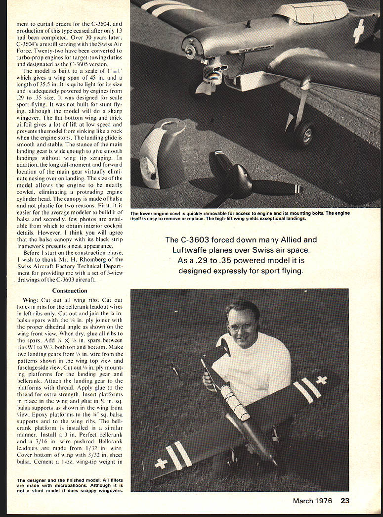
Cowl: The cowl is comprised of formers F1 and F20 and a balsa block between these formers. The two holes near the base of F20 must align with the 3/16 in. dowels previously installed in F19. The 1/4 in. hole of F1 must align with the blind nut previously installed in F2. Hollow out the balsa block to fit your engine and make cutouts for the cylinder head, exhaust and needle valve as required. Apply a coat of epoxy to inside of cowl for fuel proofing.
Stab and Fins: Cut out stabilizer and fins from 1/4 in. sheet balsa and round off leading and trailing edges as shown. Hinge elevator to the stabilizer using Klett RK2-7 hinges. Glue rudders to the fins. The rudders are offset 5/16 in. to the outside of the flying circle. Glue fins to stabilizer.
Joiner: At this point, the wing is glued in place to the balsa saddle and the empennage assembly is glued to the bottom balsa block behind former F11. When dry, add balsa block to top of stabilizer behind former F11. All blocks are now sanded to blend in with the fuselage shape.
Radiator, Gear Housing, Gear Fairing, Exhausts: The radiator consists of 1/8 in. balsa sides and 1/4 in. balsa bottom as shown in the side and cross-section views and is located on the fuselage centerline. The gear housing is made from 1/8 in. balsa sanded to shape as shown in the wing top view and fuselage side view. The gear wire passes through the center of the housing, so the housing must be cut and glued around the gear wire. The gear fairing is made from three pieces of cardboard. Piece B is bent as shown in the fairing detail view and glued to piece A, which in turn is glued to the tabs of piece C. The assembly is then glued to the front of the landing gear wire. The exhaust stacks are made from three balsa strips as shown in the detail drawing and attached to the fuselage as shown in the side view.
Finishing: Use Hobbypoxy "Stuff" to fill in all surface defects. Use microballoons to make fillet at wing and fuselage intersection. Also make fillets between fin and stabilizer, stabilizer and fuselage, gear housing and wing, and radiator and fuselage intersections. Give model two coats of clear dope and two coats of sanding sealer, sanding lightly after each coat.
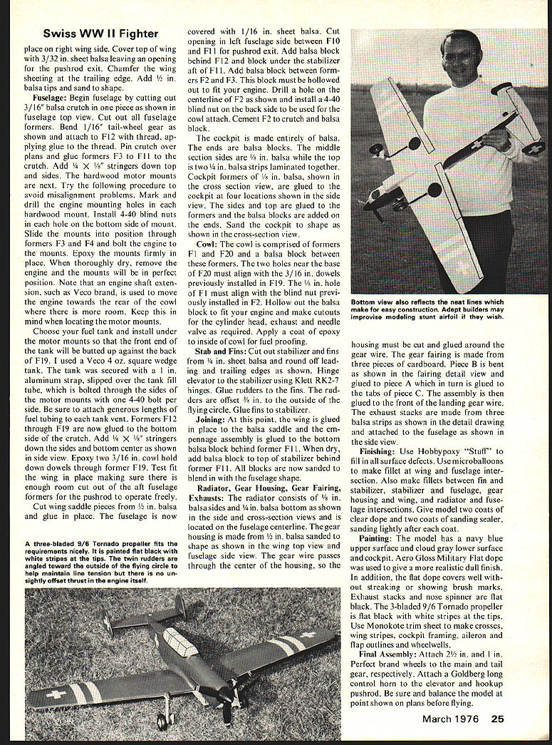
Painting: The model has a navy blue upper surface and cloud gray lower surface and cockpit. Aero Gloss Military Flat dope was used to give a more realistic dull finish. In addition, the flat dope covers well without streaking or showing brush marks. Exhaust stacks and nose spinner are flat black. The 3-bladed 9/6 Tornado propeller is flat black with white stripes at the tips. Use Monokote trim sheet to make crosses, wing stripes, cockpit framing, aileron and flap outlines and wheel wells.
Final Assembly: Attach 2-1/2 in. and 1 in. Perfection brand wheels to the main and tail gear, respectively. Attach a Goldberg long control horn to the elevator and hookup pushrod. Be sure and balance the model at point shown on plans before flying.
Transcribed from original scans by AI. Minor OCR errors may remain.

