
T-28
Dick Sardolus
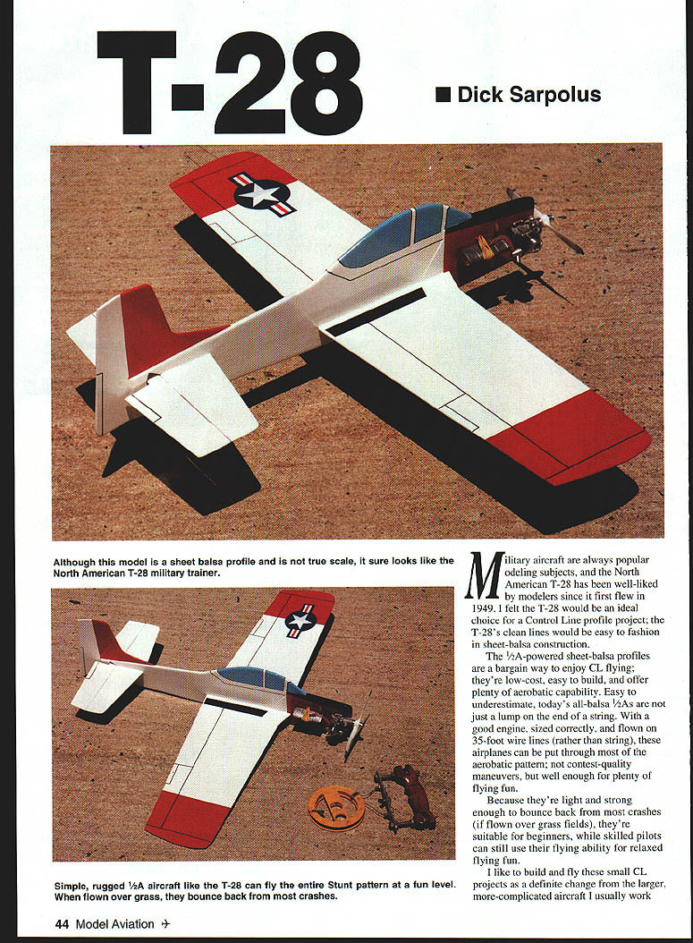
Military aircraft are always popular modeling subjects, and the North American T-28 has been well-liked by modelers since it first flew in 1949. I felt the T-28 would be an ideal choice for a control-line (CL) profile project; the T-28's clean lines are easy to fashion in sheet-balsa construction.
The 1/2A-powered sheet-balsa profiles are a bargain way to enjoy CL flying: they're low-cost, easy to build, and offer plenty of aerobatic capability. Easy to underestimate, today's all-balsa 1/2A models are not just a lump on the end of a string. With a good engine, sized correctly, and flown on 35-foot wire lines (rather than string), these airplanes can be put through most of the aerobatic pattern — not contest-quality maneuvers, but plenty of flying fun.
Because they're light and strong enough to bounce back from most crashes (if flown over grass fields), they're suitable for beginners, while skilled pilots can still use their flying ability for relaxed flying fun.
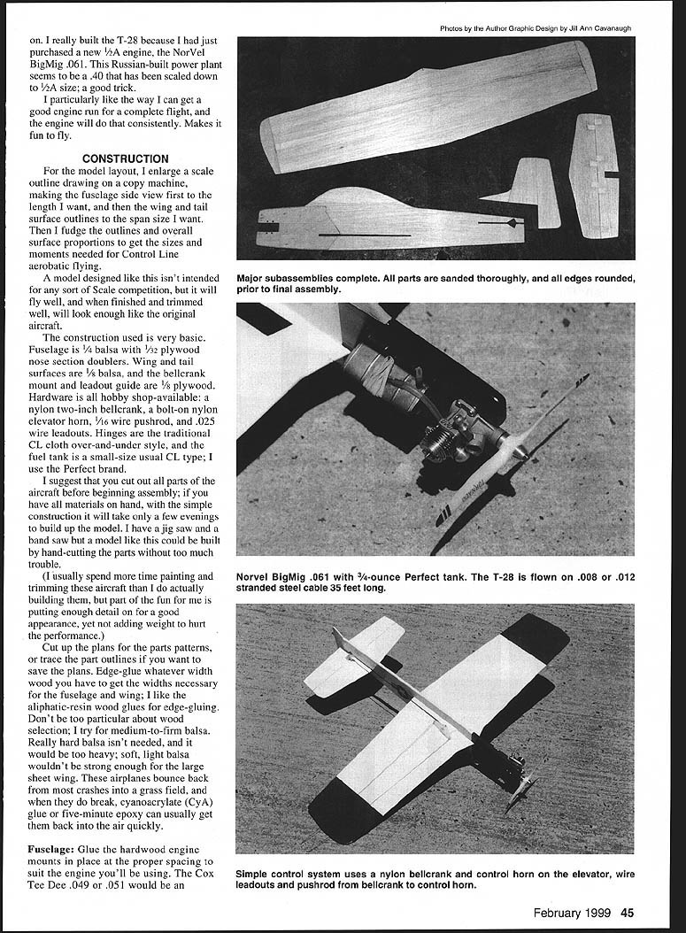
I like to build and fly these small CL projects as a definite change from the larger, more-complicated aircraft I usually work on. I really built the T-28 because I had just purchased a new 1/2A engine, the NorVel BigMig .061. This Russian-built power plant seems like a .40 scaled down to 1/2A size — a good trick. I particularly like the way I can get a good engine run for a complete flight, and the engine will do that consistently. Makes it fun to fly.
CONSTRUCTION
For the model layout, I enlarge a scale outline drawing on a copy machine, making the fuselage side view first to the length I want, and then the wing and tail surface outlines to the span size I want. Then I tweak the outlines and overall surface proportions to get the sizes and moments needed for CL aerobatic flying.
A model designed like this isn't intended for scale competition, but it will fly well and, when finished and trimmed, will look enough like the original aircraft.
The construction is very basic:
- Fuselage: 1/16" balsa (sheet)
- Wing and tail: 1/8" balsa
- Nose-section doublers: 1/32" plywood
- Bellcrank mount and leadout guide: 1/8" plywood
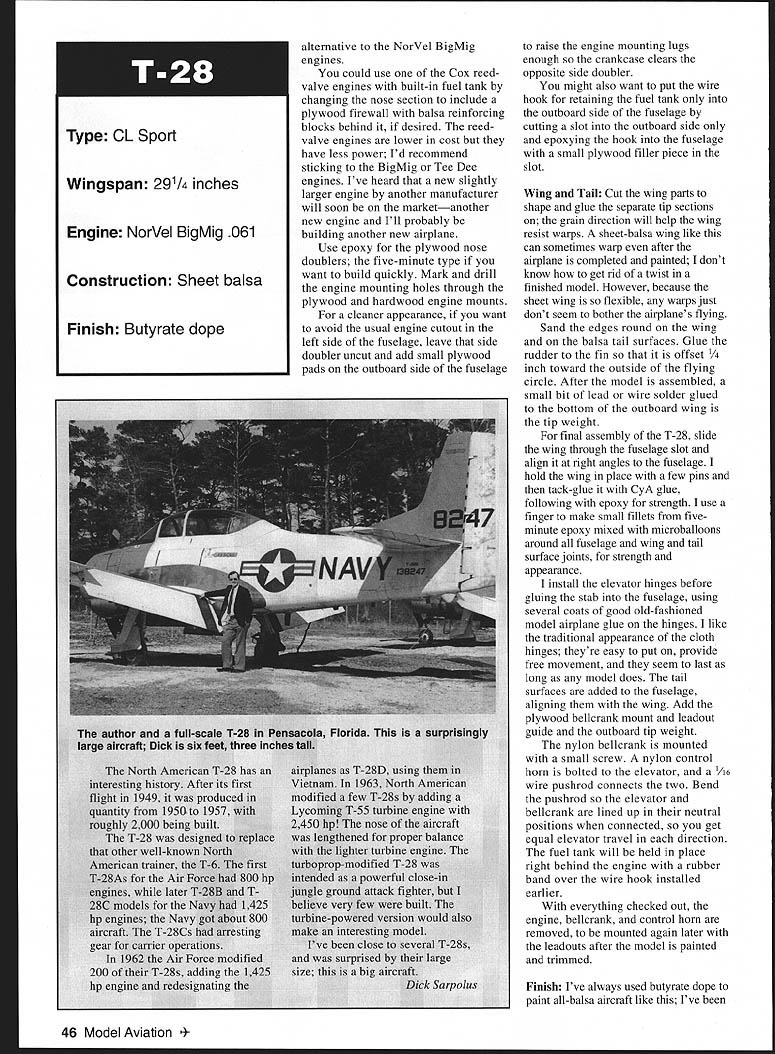
- Hardware: nylon 2" bellcrank, bolt-on nylon elevator horn, 1/16" wire pushrod, .025" wire leadouts
- Hinges: traditional CL cloth over-and-under style
- Fuel tank: small CL type (I use the Perfect brand)
I suggest cutting out all parts before beginning assembly. With all materials on hand and the simple construction, it will take only a few evenings to build the model. A jig saw or band saw helps, but a model like this can be built by hand-cutting parts without too much trouble.
(I usually spend more time painting and trimming these aircraft than building them, but part of the fun is adding enough detail for a good appearance without adding weight that hurts performance.)
Cut up the plans for parts patterns, or trace outlines if you want to save the plans. Edge-glue whatever width wood you have to get the widths necessary for the fuselage and wing; I like aliphatic-resin wood glues for edge-gluing. Don't be too particular about wood selection; aim for medium-to-firm balsa. Really hard balsa isn't needed and is too heavy; soft, light balsa isn't strong enough for the large sheet wing. These airplanes usually bounce back from most crashes into grass, and when they do break, cyanoacrylate (CyA) or five-minute epoxy can usually get them back into the air quickly.
Fuselage
- Glue hardwood engine mounts in place at the proper spacing to suit your engine. The Cox Tee Dee .049 or .051 are alternatives to the NorVel BigMig engines.
- You can use a Cox reed-valve engine with a built-in fuel tank by changing the nose section to include a plywood firewall with balsa reinforcing blocks behind it. Reed-valve engines are lower cost but have less power; I recommend sticking to the BigMig or Tee Dee engines.
- Use epoxy for the plywood nose doublers; five-minute epoxy if you want to build quickly. Mark and drill engine mounting holes through the plywood and hardwood engine mounts.
- For a cleaner appearance (avoiding the usual engine cutout in the left fuselage side), leave that side doubler uncut and add small plywood pads on the outboard side of the fuselage to raise the engine mounting lugs enough so the crankcase clears the opposite side doubler.
- Consider installing the wire hook for the fuel tank into the outboard side only: cut a slot in the outboard side, epoxy the hook into the fuselage, and add a small plywood filler piece in the slot.
Wing and Tail
- Cut the wing parts to shape and glue separate tip sections on; grain direction will help resist warps. Sheet-balsa wings can sometimes warp even after completion and painting; due to the wing's flexibility, small warps rarely affect flying.
- Sand and round the wing and tail edges.
- Glue the rudder to the fin offset 1/4" toward the outside of the flying circle.
- After assembly, add a small bit of lead or soldered wire glued to the bottom of the outboard wing as the tip weight.
- For final assembly, slide the wing through the fuselage slot and align it perpendicular to the fuselage. Hold with pins, tack-glue with CyA, then follow with epoxy for strength.
- Make small fillets from five-minute epoxy mixed with microballoons around all fuselage/wing/tail joints for strength and appearance.
- Install the elevator hinges before gluing the stab into the fuselage, using several coats of model airplane glue on the cloth hinges. Cloth hinges provide a traditional look, free movement, and durability.
- Add the plywood bellcrank mount and leadout guide, and install the outboard tip weight.
- Mount the nylon bellcrank with a small screw. Bolt a nylon control horn to the elevator and connect to the bellcrank with a 1/16" wire pushrod (7/64" in some references — ensure compatibility). Bend the pushrod so the elevator and bellcrank are aligned in neutral when connected so you get equal elevator travel each direction.
- The fuel tank will be held behind the engine with a rubber band over the wire hook installed earlier.
- After checking everything, remove the engine, bellcrank, and control horn to be mounted again later with the leadouts after painting and trimming.
MODEL DETAILS / PLAN NOTES
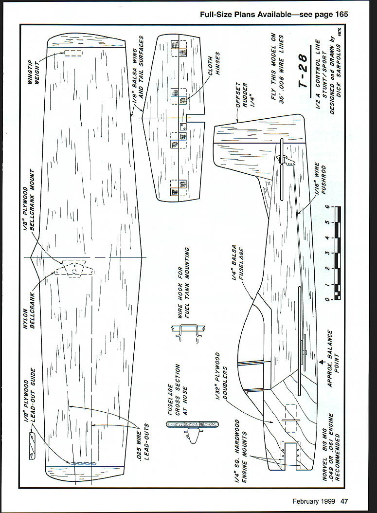
- FLY THIS MODEL ON 35' WIRE LINES
- 1/2A CONTROL LINE
- DESIGNED AND DRAWN BY DICK SARDOLUS
- WINGTIP WEIGHT
- 1/8" PLYWOOD BELLCRANK MOUNT
- NYLON BELLCRANK
- 1/8" PLYWOOD LEAD-OUT GUIDE
- .025" WIRE LEAD-OUTS
- 1/8" BALSA WING AND TAIL SURFACES
- CLOTH HINGES
- OFFSET RUDDER 1/4"
- 1/16" WIRE PUSHROD
- 1/16" BALSA FUSELAGE
- 1/32" PLYWOOD DOUBLERS
- FUSELAGE CROSS SECTION AT NOSE
- WIRE HOOK FOR FUEL TANK MOUNTING
- 1/4" SQ. HARDWOOD ENGINE MOUNTS
- APPROX. BALANCE POINT
- NORVEL BIG MIG .049 OR .061 ENGINE RECOMMENDED
FINISH
I've always used butyrate dope to paint all-balsa aircraft like this; I've been working with butyrate for 40-plus years and see no reason to change.
Use whatever paint system you prefer, but do not try for a super-smooth finish that hides all wood grain; that takes too much paint and adds too much weight. I suggest a finish that gives reasonable appearance and protects the wood from fuel and exhaust oil.
- Sand the entire model thoroughly with fine paper.
- Apply a coat of sanding sealer and sand it completely to fill much of the grain.
- Follow with four or five coats of clear dope, sanding between coats, to seal the wood.
- Spray on two or three coats of color — the minimum needed for an acceptable appearance.
- Brush on trim paint, masked with Scotch™ fine-line masking tape. Brush a coat of clear dope along the mask edge for clean lines.
- I used white overall for the T-28, with red and black trim and light blue for the canopy.
- Many paint schemes are possible: the Navy had some all-yellow examples; the Air Force used some fancy liveries on officer-transport aircraft.
- Add a few inked panel and control-surface lines for detail, then a few coats of sprayed-on clear for protection and gloss.
- Mylar® stick-on military insignia add the final touch.
Preflight
- Mount the engine, tank, and control hardware, and check for proper balance. The model will likely balance close enough without adding weight. If weight is needed, drill a 1/8" hole into the fuselage side and glue in a length of heavy solder.
- Put a washer under the front of each engine-mounting lug to provide several degrees of outthrust to help keep the lines tight while flying.
- I use .008" or .012" stranded cable flying lines; I've heard .008" solid wire lines make even less drag. I prefer stranded cable for resistance to kinks and breaks.
- Adjust the engine before launch, holding the airplane nose-high. Have the launcher keep the lines tight and point the airplane slightly toward the center of the flying circle as he/she takes a few steps and releases the model with a forward motion in a level attitude.
- Try putting the T-28 through every maneuver you can think of — and make some up.
Enjoy CL flying: the only direct-connection way to fly!
— Dick Sardolus 32 Alameda Court Shrewsbury, NJ 07702
Transcribed from original scans by AI. Minor OCR errors may remain.

