
T-3
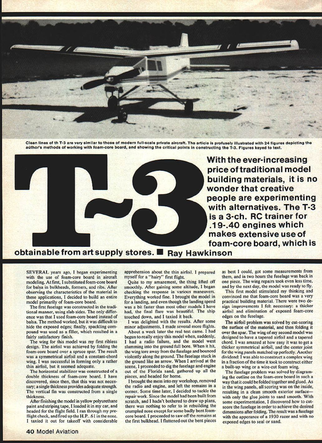
With the ever-increasing price of traditional model-building materials, it is no wonder that creative people are experimenting with alternatives. The T-3 is a 3-ch. RC trainer for .19–.40 engines which makes extensive use of foam-core board, obtainable from art supply stores. — Ray Hawkinson
Several years ago I began experimenting with the use of foam-core board in aircraft modeling. At first, I substituted foam-core board for balsa in bulkheads, formers, and ribs. After observing the characteristics of the material in these applications, I decided to build an entire model primarily of foam-core board.
The first fuselage was constructed in the traditional manner, using slab sides. The only difference was that I used foam-core board instead of balsa. The method worked, but it was difficult to hide the exposed edges; finally, spackling compound was used as a filler, which resulted in a fairly satisfactory finish.
The wing for this model was my first ribless design. The airfoil was achieved by folding the foam-core board over a spruce spar. The result was a symmetrical airfoil and a constant-chord wing. I was successful in forming only a rather thin airfoil, but it seemed adequate.
The horizontal stabilizer was constructed of a double thickness of foam-core board. I have discovered since then that this was not necessary; a single thickness provides adequate strength. The vertical fin was constructed from a single thickness.
After finishing the model in yellow polyurethane paint and striping tape, I loaded it in my car and headed for the flight field. I ran through my preflight check and fired up the H.P. 61 in the nose. I taxied it out for takeoff with considerable apprehension about the thin airfoil. I prepared myself for a "hairy" first flight.
Quite to my amazement, the thing lifted off smoothly. After gaining some altitude, I began checking the response in various maneuvers. Everything worked fine. I brought the model in for a landing, and, even though the landing speed was a bit faster than most other models I have had, the final flare was beautiful. The ship touched down, and I taxied it back.
I was delighted with the results. After some minor adjustments, I made several more flights.
About a week later the real test came. I had begun to really enjoy this model when, suddenly, I had a radio failure and the model went slamming into the ground full bore. When it hit, the wing tore away from the fuselage and bounced violently along the ground. The fuselage stuck in the ground like an arrow. When I arrived at the scene I proceeded to dig the fuselage and engine out of the Florida sand, gathered up the pieces, and headed for home.
I brought the mess into my workshop, removed the radio and engine, and left the remains in a corner. Some time later I decided to tackle the repair work. Since the model had been built from scratch and I hadn't bothered to draw up plans, there was nothing to refer to in rebuilding the crumpled nose except for some badly bent foam-core board. I proceeded to saw off the remains at the first bulkhead. I flattened out the bent pieces as best I could, got some measurements from them, and in two hours the fuselage was back in one piece. The wing repairs took even less time, and by the next day the model was ready to fly.
This first model stimulated my thinking and convinced me that foam-core board was a very practical building material. There were two design improvements I felt necessary: a thicker airfoil and elimination of exposed foam-core edges on the fuselage.
The airfoil problem was solved by cut-scoring the surface of the material and then folding it over the spar. The wing of my second model was designed to have a tapered airfoil and a tapered chord. I was amazed at how easy it was to get a thicker symmetrical airfoil, and the center joint for the wing panels matched up perfectly. Another dividend: I was able to construct a complex wing in a fraction of the time it took to construct either a built-up wing or a wire-cut foam wing.
The fuselage problem was solved by diagraming the outline on the foam-core board in such a way that it could be folded together and glued. As in the wing panels, all scoring was on the inside, resulting in a clean smooth exterior surface with only the glue joints to sand smooth. With some experimentation I discovered how to cut-score the fuselage in order to achieve the desired dimensions after folding. The result was a fuselage with the appearance of a 1930 racer and with no exposed edges to seal or sand.
The ready-to-fly weight was 4.8 lb. The K&B 40 in the nose made it a very fast model. Flight characteristics were excellent. Except for having to redesign the method for mounting the landing gear in the wings, the model was a complete success.
The next project was the T-3. The model is similar in appearance to a full-scale private aircraft. It has a tapered chord and airfoil at the wing tips — and a goof-proof method for obtaining the proper wing and stabilizer incidence.
Construction
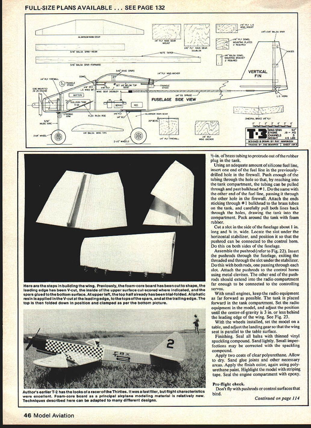
To begin, obtain a piece of 3/16-in. polystyrene foam-core board. The product consists of foam sandwiched between two pieces of white clay-coated paper and is available at most art supply stores. The T-3 requires a piece of foam board 48 x 48 in., or two pieces 30 x 40 in. My full-size patterns are for 30 x 40 in.
Begin construction by carefully outlining all necessary parts on the foam-core board. Complete the layout by filling in all internal lines.
Important terms
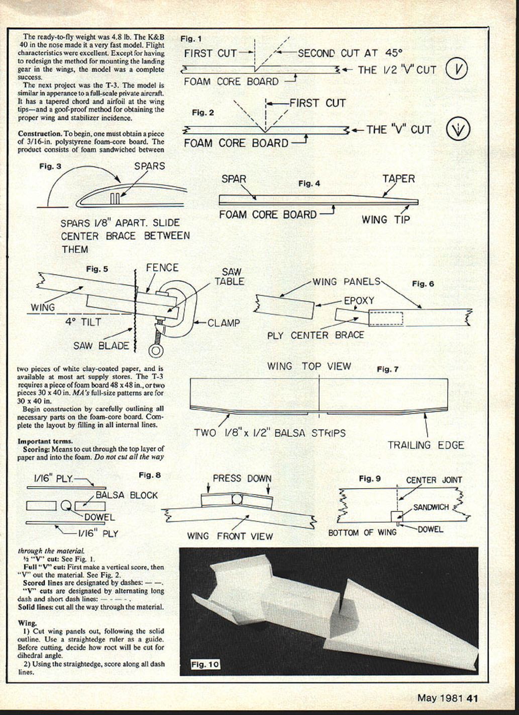
- Scoring: means to cut through the top layer of paper and into the foam. Do not cut all the way through the material.
- 1/2" "V" cut: See Fig. 1.
- Full "V" cut: First make a vertical score, then "V" out the material. See Fig. 2.
- Scored lines are designated by dashes. "V" cuts are designated by alternating long dash and short dash lines.
- Solid lines: cut all the way through the material.
Wing
- Cut wing panels out, following the solid outline. Use a straightedge ruler as a guide. Before cutting, decide how the root will be cut for the dihedral angle.
- Using the straightedge, score along all dash lines.
- "V"-out material along the area behind the leading edge. Follow the long-short dash lines.
- Glue the spars on the foam-core board in the positions marked. Note: the main spar is tapered at one end. Study Fig. 3.
- Trial-fold the top half of the wing over the spars, and line up the trailing edge. Open the fold again. Spread glue in the leading-edge "V" seam, on top of the spars, and at the trailing edge. The model is completely built with aliphatic resin (such as Sig-Bond) and, where specified, 5-min. epoxy. Fold the wing panel closed, and clamp at the trailing edge. See Fig. 4. Note: Do not allow glue to ooze into the space between the spars where the 1/8 plywood center brace will go; otherwise, trouble will be encountered later when fitting the brace between the spars.
- Second wing panel: follow steps 1, 2, and 3 above. Before gluing the spars in place on wing panel #2, merely set them in place, fold the wing closed, insert the 1/8 plywood brace between the spars, and trial-fit the wing panels. Check the alignment.
- Dihedral cut line note: In order to get a good center joint, the root end of the wing panel must be cut to compensate for the 1 3/4 to 2 in. dihedral at each wing tip. If the optional dihedral cut line was followed when cutting out the wing panel, the dihedral cut has already been accomplished. However, another method of obtaining the dihedral cut is sketched in Fig. 5, and is done after each panel is glued together.
- Epoxy the 1/8 plywood center brace in the slot between the spars on one wing panel. Wipe off any excess glue. Note: One-half of the brace will extend into the wing, and one-half will be sticking out.
- Spread epoxy on the root of the wing and on the center brace sticking out. Slide the panels together. Match up the seams. See Fig. 6.
- Glue 1/8 x 1/2-in. balsa on the trailing edge of the wing. Note: glue two layers of balsa on the trailing edge, but with the second layer, leave a 4-in. space at the center trailing edge of the wing. See Fig. 7.
- Attach the wing tip blocks.
- The leading edge of the wing is attached to the fuselage by means of a dowel in a "sandwich." Study Fig. 8.
Wing leading-edge anchor "sandwich" a) Set the bottom piece of 1/16 ply on the bottom of the wing at the wing joint (don't glue to wing). b) Epoxy the dowel and the 1/4-in. balsa blocks to the bottom piece of 1/16 ply. Press the outer edges down to conform with the dihedral angle at the wing center joint. c) Epoxy the top piece of 1/16 ply, completing the "sandwich." d) Epoxy the completed sandwich to the wing so that the dowel protrudes in front of the leading edge by about 3/8 in. See Fig. 9.
- Complete the wing by sanding the balsa to shape, being careful not to strike the paper covering. The paper should not be sanded until at least one coat of clear polyurethane has been applied as a sealer.
Fuselage
- Cut out fuselage, using a straightedge ruler as a guide.
- Score all dashed lines.
- Angle-cut all long/short-dash lines, and remove waste material resulting from the "V" process. This allows the fuselage to be folded to shape. Note: the last 9 1/2 in. of the tail section are "V"-cut, thus making folding easier. All other cuts are 1/2 "V". Remove all the foam from the last 3 1/2 in. of the tail section.
- Carefully fold the fuselage into shape. The fuselage is designed in three sections and held together by what will become the top of the fuselage.
- Fold the center box together, and epoxy the center seam. Insert some slow-drying adhesive in the fold seams.
- Fold the nose section sides into place. Position the doublers. Allow the sides to fall open, and glue the doublers in place. Use 5-min. epoxy. Wipe away any excess that oozes out. Note: the doubler acts as a guide for the installation of the firewall and bulkhead #1. See Fig. 10.
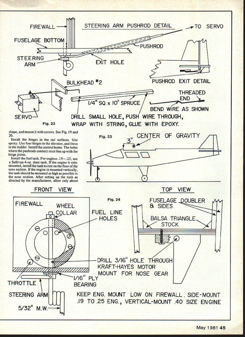
- Trial-fit the firewall. After the firewall has been drilled for the motor mount and fuel line exits (see Fig. 24), epoxy it in place. Reinforce firewall glue joints with triangle stock.
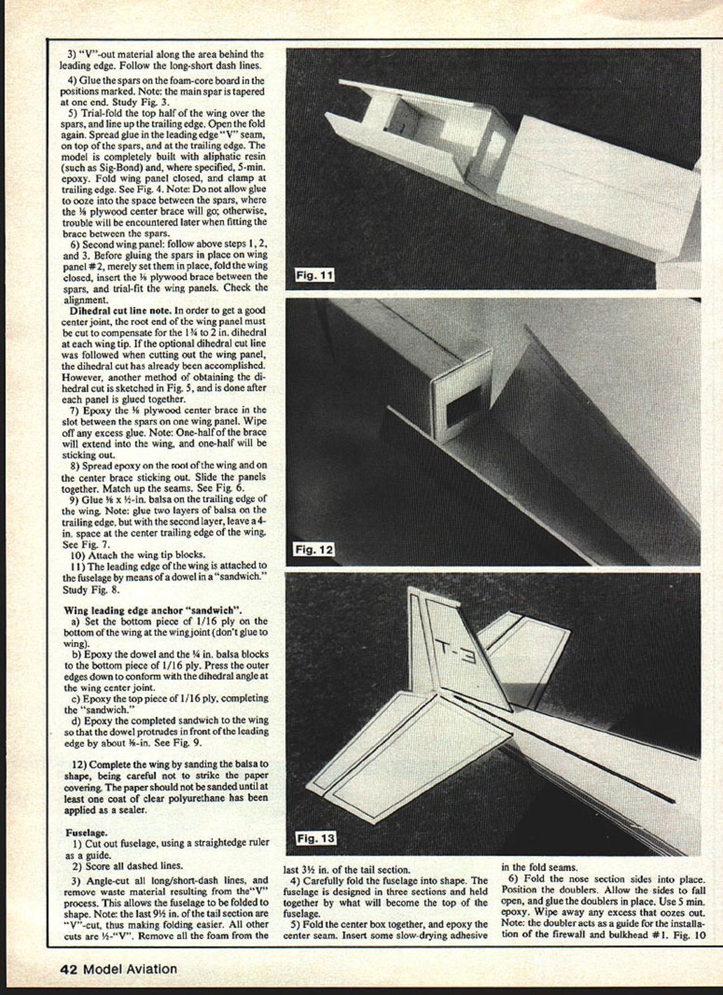
- Install bulkhead #1 in position. Note: The fuselage is upside down on the work table; be sure to install the bulkhead so that the end marked "top" will later be on top of the fuselage. Fig. 11 shows completion to this point.
- Install bulkhead #2 in the tail section. Be sure the edge marked "top" is installed correctly. Glue down the edge marked "top" first, then fold the sides into position and glue. Note: Do not close up the bottom of the fuselage till later. Fig. 12 shows bulkhead #2 installed, before gluing sides.
- Bring nose section into line with center box, and epoxy in place.
- Finish bottom of fuselage.
- Apply a coat of polyurethane to the fuselage, and set aside for curing.
Tail surfaces
- Cut out the horizontal stabilizer.
- Remove the section that is to be replaced with 1/4 x 1/4 spruce. Glue the elevator tie-bar in place.
- Remove the part that is to be replaced with the balsa tail spar. This will separate the elevators from the horizontal stabilizer. Glue the spar only to the horizontal stabilizer.
- Cut out the vertical tail surfaces.
- Remove the section that is to be replaced with a balsa spar, and glue the spar only to the trailing edge of the vertical fin.
- Face the edges of the tail surfaces with 1/16 x 1/16 balsa. Sand the balsa to shape, being careful not to strike the paper with the sandpaper.
- Prepare a quantity of sealing liquid for the balsa by thinning a small amount of vinyl spackling compound (found at any hardware store) so that it will penetrate the wood. Apply to the balsa edges, then sand smooth and seal with one coat of clear polyurethane.
Final assembly
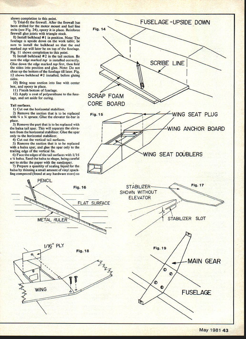
- Wing seat: Place fuselage upside down on a flat surface. Stack two pieces of scrap foam-core board beside the location of the wing seat on the fuselage. Using the scrap foam-core board as a straightedge, mark the location of the wing seat.
- Turn the fuselage right-side up, and scribe a line marking the leading and trailing edges of the wing seat. Cut and remove the wing seat plug. See Fig. 15.
- Glue the wing seat doublers and the wing anchor board in place.
Stabilizer slot
- Place the fuselage upside down on a flat surface. Using a 1-in. wide ruler, scribe a line from the back of the fuselage forward for a distance of 5/8 in. See Fig. 16.
- Measure 3/16 in. above this line, and scribe another parallel line. Do the same on the other side. Cut open the slot with an X-Acto knife.
- Note: When the horizontal stabilizer is slid all the way home in the slot (see Fig. 17), the balsa spar is still protruding behind the fuselage. The vertical fin spar will pass through the horizontal stabilizer spar, and it will have to be notched to allow for this.
Miscellaneous
- The leading edge of the wing is held in place in the wing seat by the dowel which passes through the 1/16 ply mounting plate. See Fig. 18. Slide the dowel on the wing through the hole in the mounting plate. The dowel and plate should fit against bulkhead #1 with the dowel fitting into the previously-cut relief slot at the top of bulkhead #1.
- Once a good fit is accomplished, epoxy into place the side of the plate that fits against the bulkhead. Before the epoxy has a chance to set, slide the wing home in the wing seat, thus getting a perfect alignment of the dowel and the plywood plate. Hold in place until the epoxy sets. Don't allow glue to ooze onto the dowel; otherwise, the wing may be secured permanently to the aircraft.
- The wing mounting is completed by drilling two holes at the trailing edge of the wing so that the wing can be screwed down on the rear mounting plate in the fuselage.
- Glue tail surfaces to the fuselage. Align the horizontal stabilizer with the wing. The vertical fin must be vertical.
- Glue balsa nose block in place, and carve out an opening for the engine propeller shaft to pass through. Sand to shape.
- Cut engine access hole in nose. If the engine is .19–.25, cut the hole in the right side. Cut the hole in the top for larger engines. Cut the hole large enough so that the engine can be installed in the hole and removed easily when necessary.
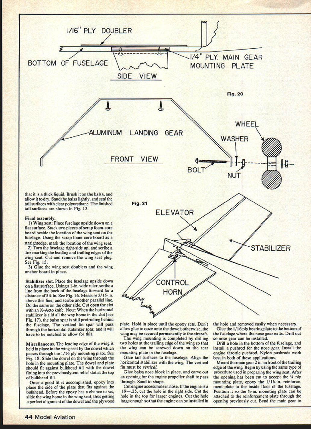
- Glue the 1/16 ply bearing plate to the bottom of the fuselage where the nose gear exits. Drill out so nose gear can be installed.
- Drill a hole in the bottom of the fuselage, and install a pushrod for the nose gear. Install the engine throttle pushrod. Nylon pushrods work best in both of these applications.
- Mount the main gear 2 in. in front of the trailing edge of the wing. Begin by using the same type of procedure used in preparing the wing seat. After the opening has been cut to accept the 1/4-in. ply mounting plate, epoxy the 1/16-in. reinforcement plate to the inside floor of the fuselage. Position it so the 1/4-in. mounting plate can be attached to the reinforcement plate through the opening previously cut. Bend the main gear to the required shape and install on the mounting plate using bolts, washers and nuts as shown. Shape, and mount it with screws. See Fig. 19 and 20.
- Install the hinges in the tail surfaces. Use epoxy. Use four hinges in the elevator, and three in the rudder. Install the control horns. The holes where the pushrods connect must line up with the hinge joints.
- Install the fuel tank. For engines .19–.25, use a Sullivan 4-oz. slant tank. If the engine is side-mounted, install the tank to rest on the floor of the nose section. If the engine is mounted vertically, the tank should be mounted as high as possible in the nose section. After setting up the tank as directed by the manufacturer, allow only about 1/2 in. of brass tubing to protrude out of the rubber plug in the tank.
- Using an adequate amount of silicone fuel line, insert one end of the fuel line in the previously-drilled hole in the firewall. Push enough of the tubing through the hole so that, by reaching into the tank compartment, the tubing can be pulled through and past bulkhead #1. Do the same with the other end of the fuel line, passing it through the other hole in the firewall. Attach the ends sticking through bulkhead #1 to the brass tubes on the tank, and carefully pull both lines back through the holes, drawing the tank into the compartment. Pack around the tank with foam rubber.
- Cut a slot in the side of the fuselage about 1 in. long and 5/8 in. wide. Locate the slot under the horizontal stabilizer, and position it so that the pushrod can be connected to the control horn. Do this on both sides of the fuselage.
- Assemble the pushrod (refer to Fig. 22). Insert the pushrods through the fuselage, exiting the threaded end through the slot under the stabilizer. Do this with both rods, one passing through each slot. Attach the pushrods to the control horns using metal clevises. The other end of the pushrods should extend into the radio compartment far enough to be connected to the controlling servos.
- With small engines, keep the radio equipment as far forward as possible. The tank is placed forward in the tank compartment. Set the radio equipment in the model and adjust the position until the center-of-gravity is 3 in. or less behind the leading edge of the wing. See Fig. 23.
- With the wheels installed, set the model on a table, and adjust the landing gear so that the wing seat is parallel to the table surface.
Finishing
- Seal all balsa with thinned vinyl spackling compound. Sand lightly. Small imperfections may be corrected with the spackling compound.
- Apply two coats of clear polyurethane. Allow to dry. Sand glue joints and other necessary areas.
- Apply the finish color, again using polyurethane paint. Highlight the model with striping tape.
- Seal the engine compartment with epoxy.
Pre-flight check
- Don't fly with pushrods or control surfaces that bind.
- Check that the control surfaces move in the proper direction when the stick is moved on the transmitter.
- Get an experienced model aircraft pilot to help you on your first flight.
Happy flying.
Parts Inventory
Plywood
- 1 — 1/4 x 2 3/4 x 3 in. Firewall
- 1 — 1/8 x 2 x 4 1/4 in. Main gear mount
- 1 — 1/16 x 3 x 3/4 in. Trailing edge wing mount
- 1 — 1/16 x 8 in. Dihedral brace
- 1 — 1/16 x 3/8 x 3/8 in. Nose gear doubler
- 1 — 1/16 x 1/8 x 3 in. Leading edge wing mount
- 2 — 1/16 x 3/16 x 3/16 in. Dowel mount plates
- 2 — 1/16 x 1/16 x 1/8 in. Front gear bearing
Spruce
- 1 — 1/4 x 3/4 x 4 in. Elevator tie
- 2 — 1/4 x 16 in. Pushrods
Balsa
- 1 — 1/4 x 2 1/2 x 2 in. Dowel
- 1 — 1/4 x 2 3/4 in. Nose block
- 1 — 1/4 x 3/4 x 19 in. Stabilizer spar
- 1 — 1/4 x 1/4 x 8 in. Fin spar
- 2 — 1/4 x 1/8 x 3/8 in. Wing tip blocks
- 2 — 1/8 x 3/16 x 1/8 in. Dowel mounting blocks
- 2 — 3/16 x 1 x 26 in. Trailing edge stock
- 2 — 3/16 x 1 x 26 in. Wing spar
- 2 — 3/16 x 1 x 8 in. Wing spar
- 1 — 3/16 x 1 x 36 in. Facing strips
- 1 — 1/16 x 1/4 x 18 in. Facing strips
- 2 — 1/4 in. Triangle stock (firewall reinforcement)
- 2 — 1/8 in. Triangle stock (wing mount reinforcement)
Hardware
- 2 — Control horns
- 1 — Aluminum main gear
- 1 — Wire nose gear
- 1 — 5/32 wheel collar
- 1 — 5/32 steering arm
- 2 — Metal pushrods
- 2 — Clevises
Other
- 3 — Wheels
- 1 — Motor mount
- Engine, Radio, Propeller, Glue, Paint, Spackling compound, Flex pushrods
Transcribed from original scans by AI. Minor OCR errors may remain.

