
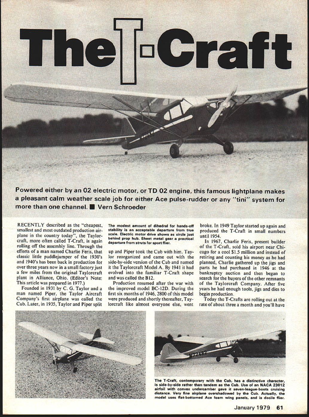
The T-Craft
Recently described as the "cheapest, smallest and most outdated production airplane in the country today," the Taylorcraft—more often called the T-Craft—is again rolling off the assembly line. Through the efforts of a man named Charlie Feris, that classic little puddlejumper of the 1930s and 1940s has been back in production for over three years now in a small factory just a few miles from the original Taylorcraft plant in Alliance, Ohio. (Editor's Note: This article was prepared in 1977.)
History
- The Taylor Aircraft Company was founded in 1931 by C. G. Taylor and a man named Piper. The company's first airplane was called the Cub.
- In 1935 Taylor and Piper split; Piper took the Cub. Taylor reorganized and produced a side-by-side version of the Cub, naming it the Taylorcraft Model A.
- By 1941 the design had evolved into the familiar T-Craft shape and was called the B12.
- Production resumed after World War II with the improved BC-12D model. During the first six months of 1946, 2,800 BC-12Ds were produced. Shortly thereafter, Taylorcraft, like many others, went bankrupt.
- Taylor restarted in 1949 and produced T-Crafts in small numbers until 1954.
Revival and Production
- In 1967 Charlie Feris sold his airport near Chicago for $1.5 million. Instead of retiring, he gathered the jigs and parts he had purchased in 1946 at the bankruptcy auction and spent five years locating and buying the remaining tools, jigs and dies from the old Taylorcraft Company.
- With those resources he began production. As of the time of this article, T-Crafts were being produced at about three per month, and buyers faced roughly a year-long wait.
- The production model is designated the F-19 Sportsman. Specifications:
- Engine: 100-hp Continental
- Maximum speed: 127 mph
- Cruise speed: 115 mph
- Rate of climb: 775 fpm
- Range: 400 miles
- Dimensions: length 22 ft. 1 in.; wingspan 36 ft.
- Airfoil: NACA 23012
- Price (at time of article): $9,250
The writer could not afford one and decided to build a model instead.
Model Choice and Power/Radio Considerations
- The chosen model was the BC-12D, virtually the same as the F-19. (A 3-view appeared in the February 1968 issue of American Aircraft Modeler.)
- The original plan was to use an Ace constant-chord wing (scale about 1" = 1'), but the builder switched to a built-up wing to keep the model as light as possible.
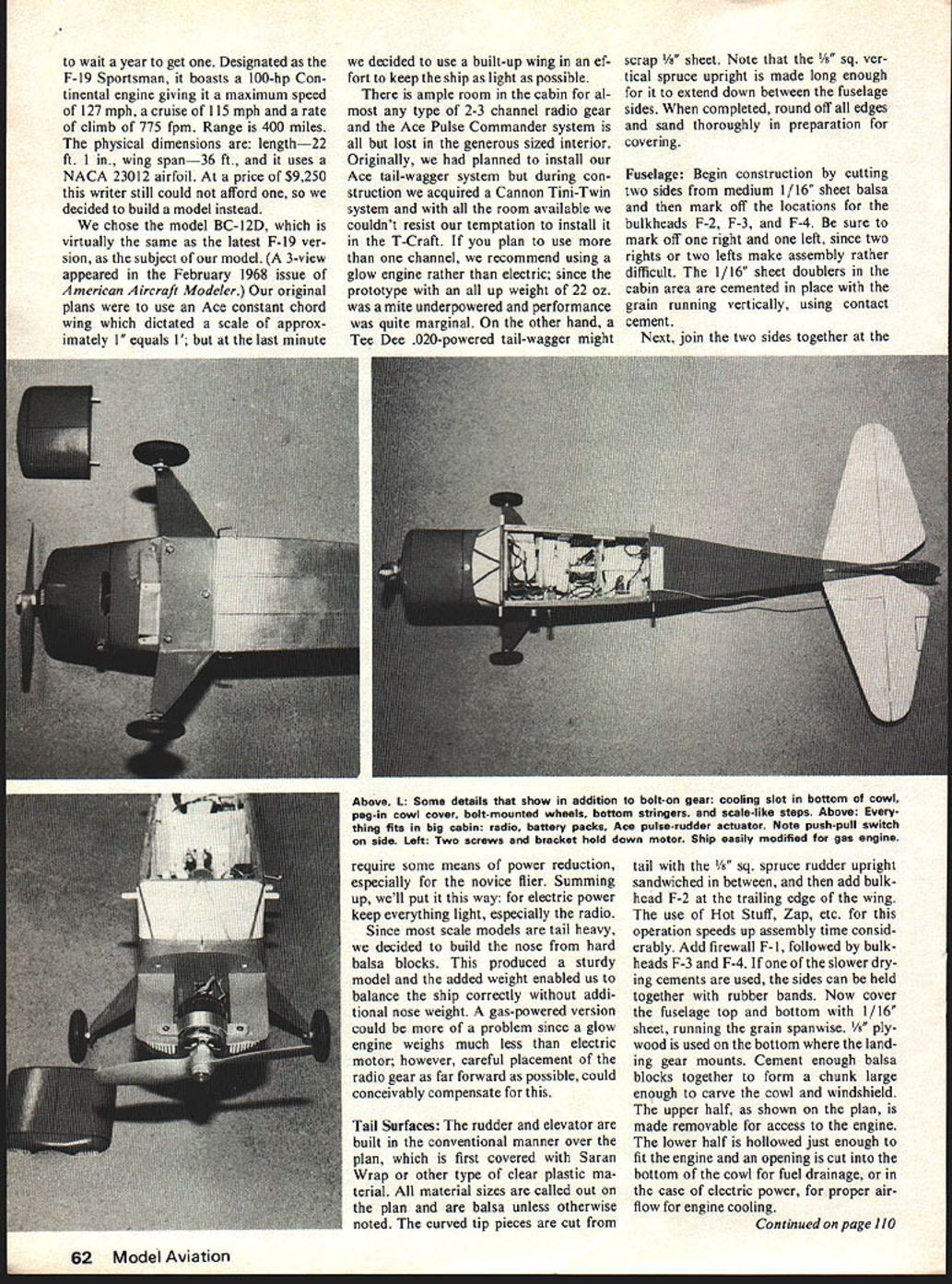
- The cabin offers ample room for almost any 2- to 3-channel radio gear. The Ace Pulse Commander system is easily accommodated in the generous-sized interior.
- The builder had planned to use an Ace tail-wagger system but acquired a Cannon Tini-Twin system during construction and installed it instead.
- Power recommendations:
- If you plan to use more than one channel, consider a glow engine rather than electric: the prototype (all-up weight 22 oz.) was slightly underpowered with electric power and performance was marginal.
- A Tee Dee .020-powered tail-wagger may require some form of power reduction, particularly for novice fliers.
- For electric power, keep everything light—especially the radio—to improve performance.
Nose Weight and Balance
- Since most scale models tend to be tail-heavy, the builder formed the nose from hard balsa blocks. This produced a sturdy nose and provided the additional weight needed to balance the model without adding separate nose ballast.
- A gas-powered version could present different balance challenges because a glow engine typically weighs much less than an electric motor. Careful placement of radio gear as far forward as possible can help compensate.
Tail Surfaces
- The rudder and elevator are built conventionally over the plan, which is first covered with Saran Wrap or another clear plastic.
- All material sizes are called out on the plan and are balsa unless otherwise noted.
- Curved tip pieces are cut from scrap 1/8" sheet.
- The 1/8" square vertical spruce upright should be made long enough to extend down between the fuselage sides.
- When completed, round off all edges and sand thoroughly before covering.
Fuselage
- Cut two fuselage sides from medium 1/16" sheet balsa and mark locations for bulkheads F-2, F-3, and F-4. Mark one side right and the other left to avoid assembly errors.
- Cement 1/16" sheet doublers in the cabin area with the grain running vertically, using contact cement.
- Join the two sides together at the tail with the 1/8" square spruce rudder upright sandwiched between them, then add bulkhead F-2 at the trailing edge of the wing. Quick-setting adhesives like Hot Stuff or Zap speed assembly.
- Add firewall F-1, followed by bulkheads F-3 and F-4. If using slower-drying cement, hold the sides together with rubber bands while drying.
- Cover the fuselage top and bottom with 1/16" sheet, running the grain spanwise. Use 1/8" plywood on the bottom where the landing gear mounts.
- Cement balsa blocks together to form a chunk large enough to carve the cowl and windshield. Make the upper half removable for engine access. Hollow the lower half just enough to fit the engine and cut an opening in the bottom of the cowl for fuel drainage or, for electric installations, for proper airflow to cool the motor.
Wing
- Cut out all ribs from the materials specified on the plan. Preferred method: pin blanks in stacks about one inch high, trace the pattern on the top of the stack, and sand to shape on a disc sander. Ensure the table is set at exactly 90 degrees to the sanding disc to keep ribs consistent.
- Cut notches for spars with a band saw, jig saw, or razor saw before splitting the ribs apart. Alternatively, cut a template from light sheet metal and make ribs one at a time.
- Pin the spars, leading and trailing edges down over the plan. After checking each rib for fit, cement them in place.
- Add wing tips cut from 1/8" sheet balsa, then add the upper spars.
- Join the two outer panels to the center section using plywood dihedral braces for reinforcement.
- Cover the leading edges and center section with 1/16" sheet (top only). Sand and shape as necessary in preparation for covering.
Covering and Finish
- The builder standardized on MonoKote (or similar plastic covering) for the wing and tail surfaces, and doped Silkspan for the fuselage.
- Steps:
- Sand the fuselage thoroughly with #400 grit sandpaper and dust off.
- Apply a coat of clear dope.
- Simulate longerons by applying 1/32" wide strips of masking tape or thread at the appropriate places shown on the plan.
- Cover the entire fuselage with one layer of lightweight Silkspan.
- Apply two coats of a 20% cornstarch / 80% clear dope mixture.
- After another sanding with #400 grit, apply two or three coats of color dope (preferably sprayed) for a satisfactory finish.
- Windows and numbers are cut from white and black MonoKote trim sheets.
RC Gear Installation
- The location of the RC gear is determined mainly by the type of power used:
- The Astro .02 electric-powered version is considerably heavier than the Tee-Dee .020, so the radio gear may need to be mounted more rearward to achieve the proper balance shown on the plan.
- The Tee-Dee-powered version will require the RC gear to be placed as far forward as possible; additional nose ballast may still be necessary.
- The Ace Pulse Commander includes excellent instructions showing several actuator mounting and torque rod installations. Any of these could be used; the installation shown on the plan is advantageous because it is invisible after completion—a desirable feature for scale aircraft.
Flying
- Never fly the T-Craft (or any model) until it has been balanced at the location shown on the plan. A tail-heavy model is especially dangerous; while a nose-heavy ship might possibly survive, a tail-heavy one can be disastrous.
- The T-Craft, like all models of this size, is strictly a calm-weather airplane. In the author's Midwest location, that usually means early morning or late evening flying sessions.
- Electric power permits these times because many fields restrict gas-powered aircraft at those hours.
- The Ace Pulse Commander radio is supplied with a good set of instructions on pulse rudder-only flying techniques.
Build your model light but sturdy, follow the manufacturers' instructions for engine and RC installation, and you will get many hours of relaxation and enjoyment from the T-Craft.
Transcribed from original scans by AI. Minor OCR errors may remain.

