

Tails for Models
William F. McCombs
So-called V-tails have been used on full-scale airplanes such as the Beechcraft Bonanza and the Davis DA-2A, and modelers have used them occasionally on free-flight (FF) duration models and radio-controlled (RC) models. To the author's knowledge, however, there have been no design procedures published for the modeler's purpose. The purpose of this article is to provide the reader with a procedure for sizing V-tails for FF and RC models.
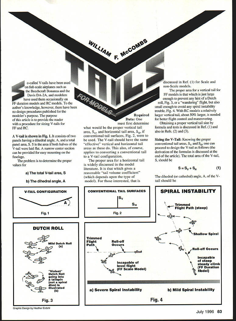
A V-tail consists of two panels having a dihedral (or cathedral) angle, A, and a total panel area, S. S is the area of both halves of the V-tail if they were laid flat. A narrow center section can be provided for easy mounting on the fuselage. The problem is to determine the proper values for:
- a) the total V-tail area, S
- b) the dihedral angle, A
Required Data
One must first determine what would be the proper vertical tail area, S_v, and horizontal tail area, S_h, if conventional tail surfaces were to be used. The V-tail should have the same "effective" vertical and horizontal tail areas as these would. This also applies to converting a conventional tail to a V-tail configuration.
The proper area for a horizontal tail is widely discussed in the model literature. It is that which gives a reasonable "tail volume coefficient" (which depends upon the type of model). For those interested, that is discussed in Ref. 1 for scale and non-scale models.
The proper area for a vertical tail for FF models is that which is just large enough to prevent any hint of a Dutch roll or a "wandering" flight, but also small enough to avoid spiral instability trouble. With RC models a relatively larger vertical tail, about 50% larger, is generally needed for better flight control and maneuvering.
Obtaining a proper vertical tail size by formula and tests is discussed in Ref. 1 and also in Refs. 2 and 3.
Sizing the V-Tail
Knowing the proper conventional tail areas, S_v and S_h, proceed to design the V-tail as follows (derivation of the formulas is discussed at the end of the article).
- Total area of the V-tail:
S = S_v + S_h (1)
- Dihedral (cathedral) angle of the V-tail:
A = arctan( sqrt(S_v / S_h) ) (2)
- The chord, or average chord, of the V-tail should be the same as that of the conventional horizontal tail if it were being used.
These values of S and A will result in a V-tail having the same "effective" vertical and horizontal areas as the conventional tail would, and hence essentially the same stability characteristics. The effective vertical tail area of the V-tail is:
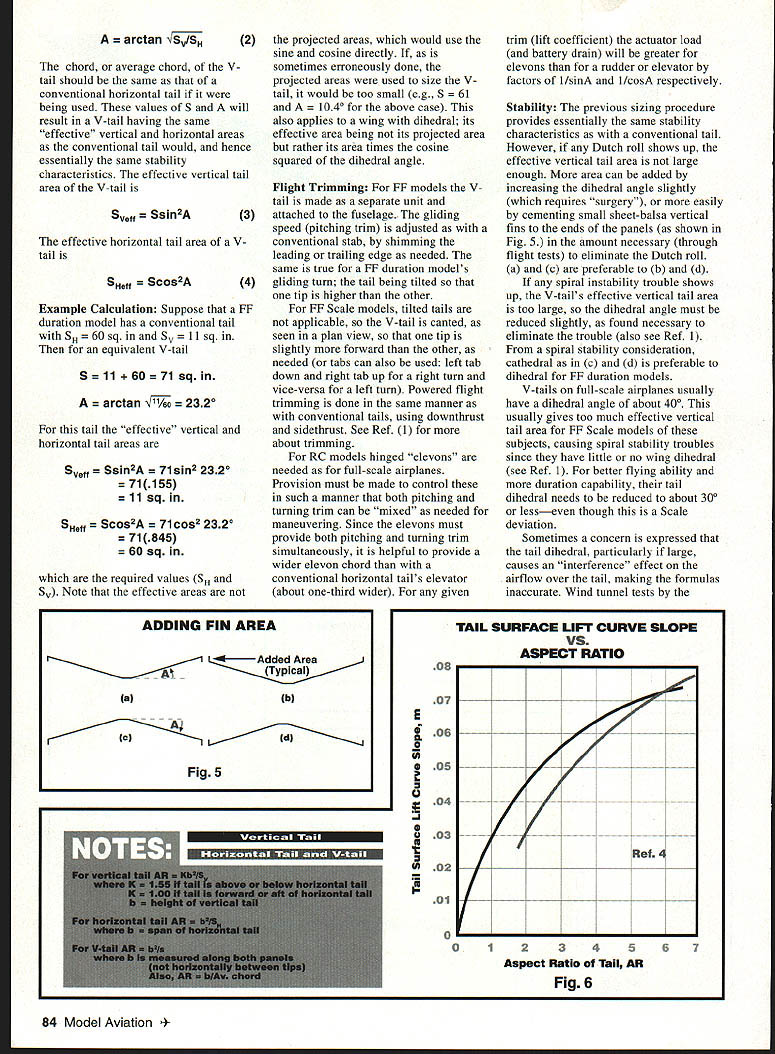
- S_Veff = S * sin^2(A) (3)
The effective horizontal tail area of a V-tail is:
- S_Heff = S * cos^2(A) (4)
Note: The effective areas are not the projected areas (which would use the sine and cosine directly). If projected areas were used to size the V-tail, it would be too small. The same principle applies to a wing with dihedral: its effective area is its area times the cosine squared of the dihedral angle.
Example Calculation
Suppose a FF duration model has a conventional tail with S_h = 60 sq. in. and S_v = 11 sq. in. Then for an equivalent V-tail:
- S = 11 + 60 = 71 sq. in.
- A = arctan( sqrt(11/60) ) = 23.2°
For this tail the effective areas are:
- S_Veff = 71 * sin^2(23.2°) = 71 * 0.155 = 11 sq. in.
- S_Heff = 71 * cos^2(23.2°) = 71 * 0.845 = 60 sq. in.
These are the required values S_v and S_h.
Flight Trimming
FF models:
- The V-tail is usually made as a separate unit and attached to the fuselage.
- Gliding speed (pitch) trim is adjusted as with a conventional stab, by shimming the leading or trailing edge as needed.
- For gliding turns the tail can be tilted so that one tip is higher than the other.
- For FF scale models, tilted tails are not applicable; the V-tail is canted in plan view so one tip is slightly more forward than the other, as needed. Tabs can also be used (left tab down and right tab up for a right turn, and vice versa for a left turn).
- Powered flight trimming is done the same as with conventional tails, using downthrust and sidethrust.
RC models:
- Hinged "elevons" are needed. Provision must be made to control these so that pitching and turning trim can be mixed for maneuvering.
- Since the elevons must provide both pitching and turning trim simultaneously, it is helpful to provide a wider elevon chord than a conventional elevator—about one-third wider.
- For any given trim (lift coefficient) the actuator load (and battery drain) will be greater for elevons than for a separate rudder or elevator by factors of 1/sin(A) and 1/cos(A), respectively.
See Ref. 1 for more about trimming.
Stability
The sizing procedure above provides essentially the same stability characteristics as a conventional tail. However:
- If Dutch roll appears, the effective vertical tail area is not large enough. More area can be added by slightly increasing the dihedral angle (requires structural modification) or more easily by cementing small sheet-balsa vertical fins to the ends of the panels in the amount necessary (determined by flight tests) to eliminate the Dutch roll. Adding fin area at the tips is often effective.
- If spiral instability appears, the V-tail's effective vertical tail area is too large; reduce the dihedral angle slightly as needed to eliminate the trouble.
- From a spiral stability standpoint, cathedral dihedral is preferable to simple dihedral for FF duration models.
- V-tails on full-scale airplanes usually have dihedral angles of about 40°. This is often too much effective vertical area for FF scale models (which typically have little or no wing dihedral) and can cause spiral instability. For better flying ability and duration, reduce the tail dihedral to about 30° or less for FF scale models, even though this is a scale deviation.
Wind-tunnel tests by NACA many years ago showed that interference effects of tail dihedral on airflow are insignificant for dihedral angles up to at least 40°, larger than any model or full-scale airplane really needs.
Notes on Aspect Ratio and Lift-Curve Slope
The formulas above are accurate only when the vertical tail and the V-tail are equally effective in generating lateral lift. In many cases this is not true because the V-tail's aspect ratio (AR) is often much larger than the vertical tail it replaces. A larger AR means more lift-generating ability, so the effective vertical area computed by the formulas may be too large—sometimes substantially so. This can lead to spiral instability on FF models.
To compensate, reduce the value of S_v before using it in the formulas by multiplying S_v by the factor (m_v / m_v-tail), where m_v is the lift-curve slope of the original vertical tail and m_v-tail is the lift-curve slope of the V-tail. Values of m can be obtained from a tail surface lift-curve slope vs. aspect-ratio chart (see Fig. 6 referenced in the original article). AR calculations:
- Vertical tail AR = b^2 / S_v
- where b = height of the vertical tail
- use K = 1.55 if the tail is above or below the horizontal tail
- use K = 1.00 if the tail is forward or aft of the horizontal tail
- Horizontal tail AR = b^2 / S_h
- where b = span of the horizontal tail
- V-tail AR = b^2 / S
- where b is measured along both panels (not the horizontal distance between tips)
- also AR = b / average chord
Example of refinement:
- Given S_v = 11 sq. in., vertical-tail height b = 3.8 in., and the vertical tail is forward or aft of the horizontal tail:
- AR_v = 3.8^2 / 11 = 1.31 → m_v ≈ 0.034 (from Fig. 6)
- For horizontal tail S_h = 60 sq. in., span = 16 in.:
- AR_h = 16^2 / 60 = 4.27 → m_h ≈ 0.060
- Revised S_v = 11 * (0.034 / 0.060) = 6.23
- Then:
- S = 6.23 + 60 = 66.23
- A = arctan(6.23 / 60) = 17.9°
If the vertical tail were above or below the horizontal tail (use K = 1.55):
- AR_v = 1.55 * 3.8^2 / 11 = 2.03 → m_v ≈ 0.045
- S_v = 11 * (0.045 / 0.060) = 8.25
- S = 8.25 + 60 = 68.25
- A = arctan(8.25 / 60) = 20.3°
Since the span and S of the V-tail are now known (span ≈ S / chord), one can recalculate AR for the V-tail and iterate for a better value of S and A.
For RC and control-line (CL) models this refinement is usually not necessary, since any excessive S_Veff is smaller and less likely to be problematic than for FF models.
Approximate Sizes for Typical FF Duration Models
For those who do not want to go through the full effort, a rough approximation for currently typical FF designs:
- Assume horizontal tail area ≈ 30% of the wing area and AR ≈ 4.5.
- For gas models assume vertical tail ≈ 4% of the wing area with AR ≈ 1.3.
- For rubber models assume vertical tail ≈ 6% of the wing area with AR ≈ 1.6.
- With a relatively long fuselage, a smaller horizontal tail of about 20–25% of the wing area may be more realistic.
In the end, a satisfactory vertical tail size for any model is assured only by flying tests (see Refs. 1, 2, and 3). For a new model this may involve considerable cut-and-try efforts; for a V-tail these efforts are more troublesome but can be greatly reduced by the formulas and procedures given above.
Adding Fin Area
If additional vertical effectiveness is required, small sheet-balsa fins can be cemented to the tips of the V-tail panels. This is an easy way to tune out Dutch roll without major structural changes.
Derivation of Formulas
Derivations of formulas (1) through (4) are not presented here because of space requirements and their complexity. Anyone wanting them can send a two-stamp SASE to the author at the address given in Ref. 1.
References
- Making Scale Model Airplanes Fly, by W. F. McCombs, 1994 Revision (non-scale also), Aircraft Data, Box 763576V, Dallas, TX 75224; $14.95.
- "A Practical Approach to Spiral Stability," 1994 National Free Flight Society Symposium, pp. 54–61. Corrected copy available from the address in Ref. 1.
- "Vertical Tail Size for Models," Model Aviation, March–April 1992. Corrected reprints with comments available from the address in Ref. 1 for $2.95 and a two-stamp SASE.
- Airplane Performance, Stability and Control, Perkins and Hage, John Wiley & Sons, 1949.
Transcribed from original scans by AI. Minor OCR errors may remain.

