
Tamecat
ON MORE THAN one occasion, a good friend of mine has been known to say, "There are only two types of aircraft—fighters and targets." Now, while this colorful gentleman's tongue-in-cheek comment may be somewhat questionable, it's still a pretty safe bet that most newcomers to our sport would find far greater inspiration if their first RC models looked a little bit more like modern jet fighters than like one of my friend's proverbial targets.
We all know that fighter aircraft are designed to go fast and kill the enemy, and that these qualities have nothing whatsoever to do with the purpose of RC trainers. Still, if there were such a thing as a truly gentle, yet mildly aerobatic sport/trainer cleverly disguised to create the illusion of a combat-ready jet fighter, wouldn't that make the uninspiring concept of flight training a much less bitter pill to swallow?
Can today's aspiring RC flier find such an airplane? Absolutely... it's the F-14 Tamecat!
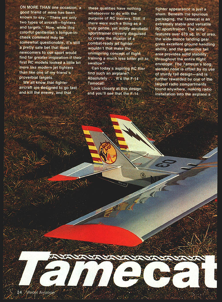
Look closely at this design, and you'll see that the F-14 fighter appearance is just a sham. Beneath the spurious packaging, the Tamecat is an extremely stable and versatile RC sport/trainer. The wing features over 670 sq. in. of area, the wide-stance landing gear gives excellent ground handling ability, and the generous tail area provides solid stability throughout the entire flight envelope. The Tamecat's long, slender nose is offset by its sturdy tail design—and is further rewarded by one of the largest radio compartments found anywhere, making radio installation into the airplane a pleasure.
The Tamecat's most visible difference from currently available sport models is its second vertical fin and rudder. There's no question that the airborne appearance of those twin tails is most exciting and well worth the small extra effort in building them. In spite of this unique feature, all control linkages—including rudders—are straightforward and surprisingly simple to make and install. Because the radio compartment is in the rear of the model, the elevator and rudder pushrods are short. This feature prevents the modeler from having to construct traditional, more complicated three-part pushrods.
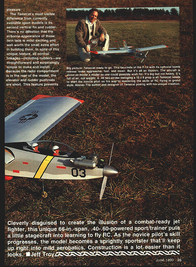
Cleverly disguised to create the illusion of a combat-ready jet fighter, this unique sport/trainer puts a little stagecraft into learning to fly RC. As the novice pilot's skill progresses, the model becomes a sprightly sportster that'll keep up right into mild aerobatics. Construction is a lot easier than it looks.
- Jeff Troy, designer
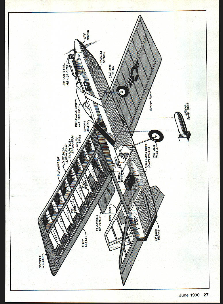
- Drawn by John Hunton, 1989
Specifications
- Span: 68 in.
- Length: 49-1/2 in.
- Engine: .40–.50 two-stroke or .45–.60 four-stroke
- Wing area: over 670 sq. in.
Construction
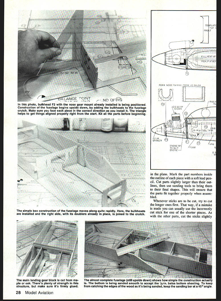
Begin by cutting out the model's parts using the templates provided. Mark part numbers inside the outline of each piece with a soft-lead pencil. Cut parts slightly larger than the outlines; use sanding tools to bring them to their final shapes. This will ensure parts fit together properly when assembled.
Whenever you cut sticks, try to cut the longer ones first; that way a mistake can usually be used as a shorter piece. As other parts are cut, cut sticks slightly oversize and finish them to exact size with sanding.
Tape the plans flat on a surface that will accept pins (a hollow-core door works well), then cover them with waxed paper to prevent the model's structures from becoming stuck to the plans as you build.
The prototype Tamecat models were built entirely with Pacer Technology's Zap-A-Gap CyA (cyanoacrylate) glue. Loctite slow-setting epoxy was used on the nylon hinges. While those adhesives are recommended, other similar products will also yield satisfactory results.
Horizontal stabilizer and elevator
Pin the 1/4 x 1-in. trailing edge in place, then fit on and glue the two 1/4 x 1-in. center ribs. Add S-1 to the center ribs. Cut and fit the leading edges and tips from 1/4 x 1/2-in. balsa, then glue and pin them in place. Add the six 1/8 x 3/4-in. balsa stick ribs to complete the basic stabilizer construction.
Use a sanding block fitted with #100 paper to sand the face and back of the stabilizer until smooth, then bring the outer perimeter to its final shape. Round the tips and leading edges, but leave the trailing edge of the stabilizer flat.
Mark the location of the five hinges on the stabilizer and on the 1/4 x 2-in. balsa elevator, then cut the hinge slots in both pieces (E.J. Lind's Digger is a useful tool for this task). After cutting the hinge slots, sand the elevator tips and trailing edge round, then bevel the leading edge to a V shape.
Fit the hinges, using no glue, to make certain there is no binding and that the elevator travels smoothly in both directions. When satisfied, remove the five hinges and set the parts aside.
Vertical stabilizers and rudders
The Tamecat's verticals are assembled in the same manner as the horizontal stabilizer and elevator. Make two of each fin and rudder.
Pin the R-1 fin base in place. Cut and fit the leading edge, trailing edge, and R-2 tip. Complete the fin by adding two 1/8 x 1/4-in. balsa ribs.
Mark the hinge locations, then cut hinge slots in both fins and both rudders. Sand the vertical fins and rudders the same way you did the stabilizer/elevator. Remember that the rudder leading edges are beveled to a V shape, while the trailing edges of the fins should be sanded flat.
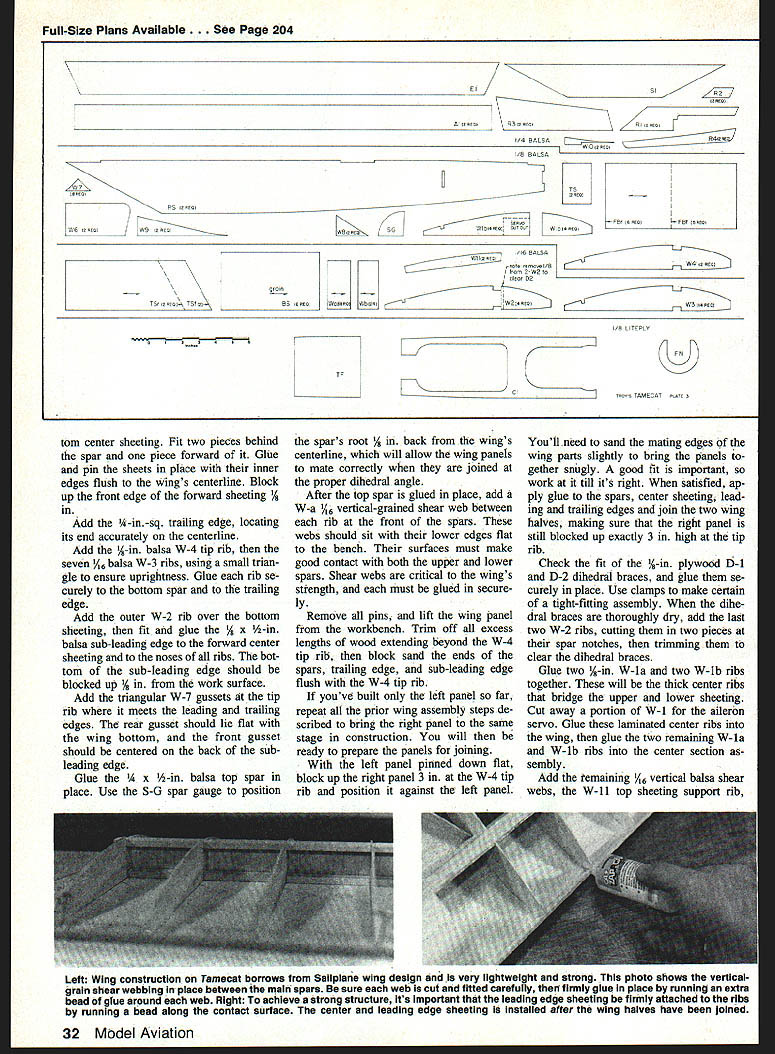
Wing
Fit the 1/4 x 1/2-in. balsa bottom spar, making certain that the end meets the wing centerline exactly. Keep all extra lengths of wood at the tip end of the wing. Cut and fit three pieces of 1/16 x 4-in. bottom spar webbing: two behind the spar and one forward of it. Glue and pin the sheets in place with their inner edges flush to the wing's centerline. Block up the front edge of the forward sheeting 1/8 in.
Add the 1/4-in.-sq. trailing edge, locating its end accurately on the centerline.
Add the 1/4 x 1/2-in. balsa W-4 tip rib, then the seven 1/4-in. W-3 ribs, using a small triangle to ensure uprightness. Glue each rib securely to the bottom spar and to the trailing edge.
Add the outer W-2 rib over the bottom sheeting, then fit and glue the 1/8 x 1/2-in. balsa sub-leading edge to the forward center sheeting and to the noses of all ribs. The bottom of the sub-leading edge should be blocked up 1/8 in. from the work surface.
Add the triangular W-7 gussets at the tip rib where it meets the leading and trailing edges. The rear gusset should lie flat with the wing bottom, and the front gusset should be centered on the back of the sub-leading edge.
Glue the 1/4 x 1/2-in. balsa top spar in place. Use the S-G spar gauge to position the spar's root 1/8 in. back from the wing's centerline, which will allow the wing panels to mate correctly when joined at the proper dihedral angle.
After the top spar is glued in place, add a W-4 1/8-in. vertical-grained shear web between each rib at the front of the spars. These webs should sit with their lower edges flat to the bench and must make good contact with both the upper and lower spars. Shear webs are critical to the wing's strength, and each must be glued in securely.
Remove all pins, lift the wing panel from the workbench, trim off all excess lengths of wood extending beyond the W-4 top rib, then block sand the ends of the spars, trailing edge, and sub-leading edge flush with the W-4 tip rib.
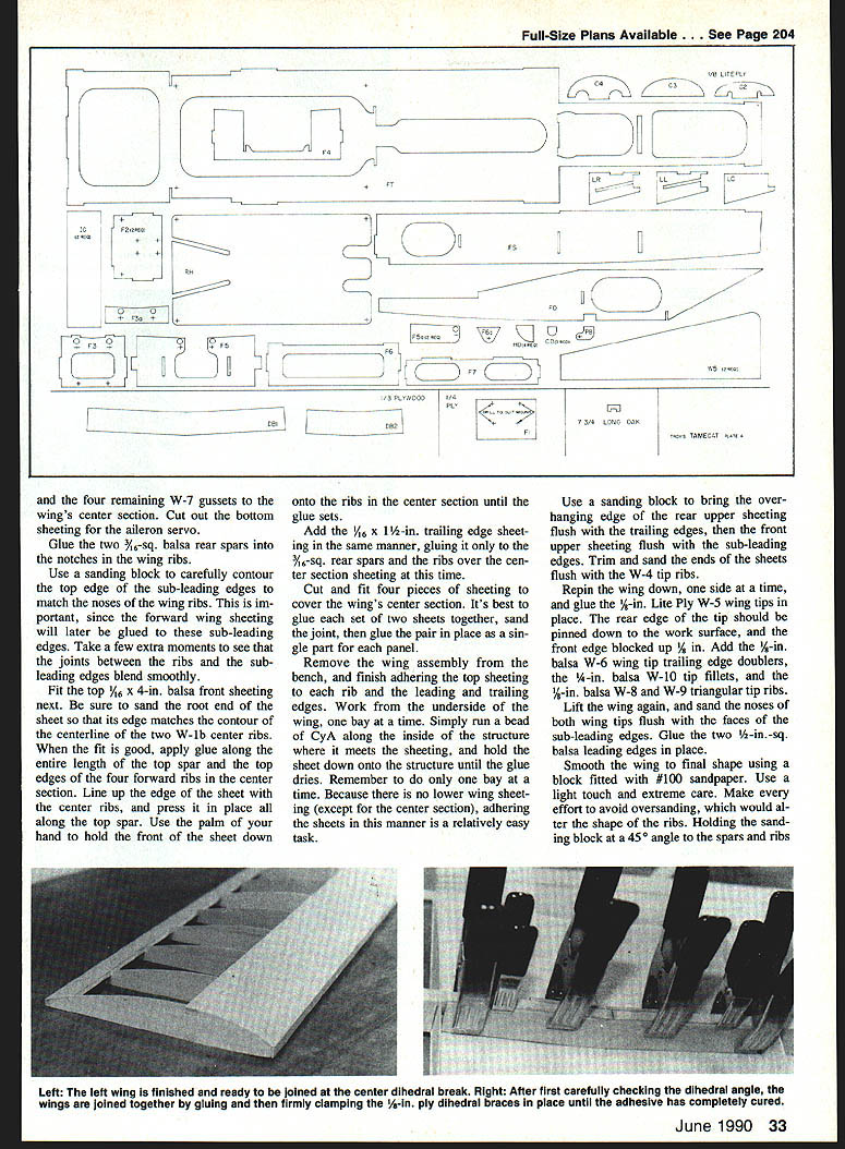
If you've built only the left panel so far, repeat all prior wing assembly steps to bring the right panel to the same stage. You will then be ready to prepare the panels for joining.
With the left panel pinned down flat, block up the right panel 3 in. at the W-4 tip rib and position it against the left panel. Sand the mating edges as necessary for a snug fit. When satisfied, apply glue to the spars, center sheeting, leading and trailing edges and join the two wing halves, making sure the right panel is still blocked up exactly 3 in. high at the tip rib.
Check the fit of the 1/8-in. plywood D-1 and D-2 dihedral braces, and glue them securely in place. Use clamps for a tight-fitting assembly. When the dihedral braces are dry, add the last two W-2 ribs, cut to fit into the pieces at their spar notches and trimmed to clear the dihedral braces.
Glue laminated center ribs (W-1a and W-1b combinations) into the wing. Cut away a portion of W-1 for the aileron servo. Add the remaining 1/16-in. vertical balsa shear webs, the W-11 top sheeting support rib, and 1/8-in. balsa top sheeting. Sheet the remaining top sheeting back to the center section, making sure of a tight fit at all joints. When dry, sand the top sheeting smooth and true, then install the 1/4 x 1/2-in. balsa nose block and fair it to the wing leading edge.
Glue the two 3/16-in.-sq. balsa rear spars into the notches in the wing ribs. Use a sanding block to carefully contour the top edge of the sub-leading edges to match the noses of the wing ribs so the forward wing sheeting will bond cleanly. Fit the top 1/16 x 4-in. balsa front sheeting next. Sand the root end of the sheet so its edge matches the contour of the centerline of the two W-1b center ribs. Apply glue along the entire length of the top spar and the top edges of the four forward ribs in the center section, line up the edge of the sheet with the center ribs, and press it in place until the glue sets.
Add the 1/16 x 1-1/2-in. trailing edge sheeting, gluing it only to the 3/16-in.-sq. rear spars and the ribs over the center section sheeting at this time. Cut and fit four pieces of sheeting to cover the wing's center section. It's best to glue each set of two sheets together, sand the joint, then glue the pair in place as a single part for each panel.
Finish adhering the top sheeting to each rib and the leading and trailing edges, working one bay at a time from the underside. Because there is no lower wing sheeting (except for the center section), adhering the sheets this way is relatively easy.
Use a sanding block to bring the overhanging edge of the rear upper sheeting flush with the trailing edges, then the front upper sheeting flush with the sub-leading edges. Trim and sand the ends of the sheets flush with the W-4 tip ribs.
Re-pin the wing down, one side at a time, and glue the 1/16-in. Lite Ply W-5 wing tips in place. The rear edge of the tip should be pinned down to the work surface, and the front edge blocked up 1/8 in. Add the 1/8-in. balsa W-6 wing tip trailing edge doublers, the 1/2-in. balsa W-10 tip fillets, and the 1/4-in. balsa W-8 and W-9 triangular tip ribs.
Lift the wing again, sand the noses of both wing tips flush with the faces of the sub-leading edges, and glue the two 1/2-in.-sq. balsa leading edges in place.
Smooth the wing to final shape using a block fitted with #100 sandpaper. Use a light touch and care to avoid oversanding, which would alter the shape of the ribs. Holding the sanding block at a 45° angle to the spars and ribs will help preserve the rib contours.
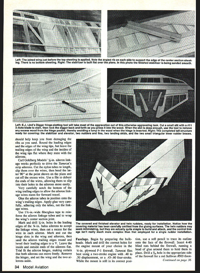
Carl Goldberg Models' 1/8-in. aileron linkage works perfectly to drive the Tamecat's strip ailerons. Cut the nylon tubes to length, slip them over the wires, then bend the latter 90° at the point shown on the plans and cut off the excess wire. Use a file to deburr the ends of the wires, allowing them to slip into their holes in the ailerons more easily.
Very carefully notch the bottom of the wing trailing edges to allow the aileron linkage wires room for forward travel. Glue the aileron tubes in position onto the wing's trailing edges, applying glue carefully to adhere only the tubes, not the linkage wires.
Use 1-1/2-in.-wide fiberglass tape to reinforce the aileron linkage tubes and to wrap the wing's center section joint.
Mark and drill 1/8-in. holes in the leading edges of the 1/4-in. balsa ailerons to accept the linkage wires. Trim the ailerons and cut the hinge slots in the wing and ailerons, then sand the aileron trailing edges round and bevel their leading edges to a V. Leave the inside and outside ends of the ailerons flat. Trial fit the aileron hinges, making certain that both ailerons can move freely. Remove the hinges, and set the wing and the two ailerons aside.
Fuselage
Begin by preparing the bulkheads. Mark and drill the correct holes for the engine mount of your choice in the 1/4-in. plywood F-1 firewall. Tamecat flies best using a two-stroke engine with .40 to .50 displacement, or a .45–.60 four-stroke. While the mount is in its correct position on the face of the firewall, insert 4-40 blind nuts behind the firewall, running a bead of glue around them to hold them in place. Drill a 1/16-in. hole in the appropriate side of the firewall for the Red Sullivan #503 throttle linkage guide tube.
Glue the two 1/4-in. Lite Ply F-2 bulkheads together, then drill a 1/8-in. hole for the throttle pushrod tube and four 1/16-in. holes for the Carl Goldberg nose-gear bearing mounting bolts. Install the nose-gear bearing on the back of the bulkhead at an angle.
Add the 1/16-in. Lite Ply F-3A doubler to the rear of the 1/8-in. Lite Ply bulkhead F-3. Drill two 1/16-in. holes for the wing hold-down dowels and two 3/16-in. holes for the throttle and nose-gear pushrod tubes. The guide tube for the nose gear must be located on the side of the fuselage opposite the throttle guide tube.
Add the two 1/8-in. Lite Ply F-5A doublers to the front side of the 1/8-in. Lite Ply F-5 bulkhead. Drill two 1/16-in. holes for the wing dowels and two 3/16-in. holes for the throttle and nose-gear pushrod tubes.
Prepare the 1/4-in. Lite Ply fuselage crutch by scoring the top of the crutch with several light passes of your razor knife, just behind the location of bulkhead F-6 and completely across the entire width of the piece. Cut approximately halfway through so the rear of the crutch can be bent downward 1/8 in.
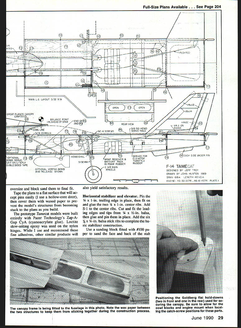
Glue F-2 into the fuselage crutch with the nose-gear bearing facing rearward. Use a small triangle to ensure the bulkhead is glued at 90° to the crutch. In the same manner, add F-3 with the doubler facing to the rear, then add F-5 with its doubler facing forward. When installing F-3 and F-5, hold the fuselage crutch down onto the tops of these bulkheads until the glue dries to ensure the angle of the fuselage top will match the wing's dihedral. Note that the firewall and rear bulkhead F-7 are not installed until later.
Build the rear fuselage sides, making sure to make a left and a right. Glue the 1/8-in. Lite Ply R-D doublers to the 1/8-in. balsa R-S rear fuselage sides. Add two 1/4-in. Lite Ply LL or LR landing gear doublers and the LC retaining plate to each side assembly—two LLs for the left side and two LRs for the right.
Glue the rear fuselage sides to the crutch and to bulkheads F-5 and F-6, ensuring all pieces mate tightly. From the scored line at F-6, bring the rear of the crutch down so that it mates with the sides. When properly aligned, add bulkhead F-7 and glue all tail joints securely.
Trial fit the forward 1/8-in. Lite Ply fuselage sides into the notches in F-5 and along the front of the crutch. Tuck the tabs on F-2 and F-3 into the slots in the fuselage sides. After this assembly is understood, glue the sides in place securely from F-2 through F-5.
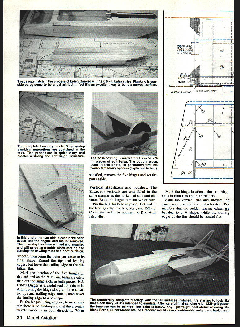
Glue the 3/4-in. hardwood landing gear block in place between the rear sides, over the notches in LL-LC and LR-LC, and along bulkhead F-5.
Gently spread the fuselage rear sides apart and slide the F-4 3/8-in. Lite Ply bulkhead into the notches in the forward fuselage sides. When seated properly, glue F-4 in place.
Glue four 1/4-in. Lite Ply H-D hatch corner doublers to the undersides of the crutch. Install the two 5/16-in. diameter wing hold-down dowels.
From the open bottom of the model, glue a T-5 tank floor spacer to the inside of each fuselage side in the fuel tank compartment. Add the 1/16-in. Lite Ply T-F tank floor, followed by two 1/4-in. triangle strip supports, one to each side.
Use a sanding block over the entire bottom of the fuselage to flatten it enough to accept the 1/8-in. balsa bottom sheeting. Glue the rear sheeting first, starting from F-4 and working toward the rear, then add the front bottom sheeting from F-4 forward. Trim and sand the bottom sheeting flush with the sides, the firewall, and F-7.
Use a straight pin through the bottom sheeting to find the slot for the gear wires in the hardwood landing gear block, then cut the bottom sheeting away from the slot. Use a 5/32-in. drill bit to drill two holes through the block for the main gear wires. Angle the bit carefully, then drill down through the block and into the slots for the wires in the LL and LR doublers.
Use the straight pin method on the front bottom sheeting to locate the hole in the nylon nose gear bearing. Drill a 5/32-in. hole through the sheeting for the nose gear.
Fit the two 1/8-in. Lite Ply I-C intake covers. Sand their top and bottom edges to an angle so they fit snugly between the bottom sheeting and the fuselage crutch. Glue the covers in place, then sand their outer edges flush with the rear fuselage sides.
Round the bottom and back edges of the two 1/4-in. balsa R-4 tail skids, but leave the edges that will be glued to the fuselage flat. Set the skids aside.
Sand the edges of the radio compartment cover round, and tape the cover over the radio hatch. Drill a 5/16-in. hole at each corner of the cover, through the crutch and into the four hatch corner doublers. Screw the cover down with #4 sheet metal screws, then remove the screws and set the hatch cover aside. Put a few drops of glue into each screw hole in the crutch. When dry, screw the four #4 hatch screws back into the fuselage and remove them. This hardens the threads in the wood to keep them from stripping when access to the radio compartment is frequently required.
Canopy assembly
Begin by laying a piece of waxed paper over the top of the forward fuselage area. Pin the 1/8-in. Lite Ply canopy assembly floor in place on top of the crutch. Glue the three 1/8-in. Lite Ply bulkheads to the floor. Add the three 1/8-in. Lite Ply C-D doublers for the hold-down screws to the C-2 front and C-4 rear bulkheads. Install three Carl Goldberg Models' flat nylon hold-downs onto the canopy bulkheads, and screw their shoulder screws into the firewall and the F-3 bulkhead. Position the two forward hold-downs 1/8 in. outside the outline you drew on the firewall earlier.
Plank the canopy area with 1/8 x 1/4-in. balsa strips. Start by fitting the first plank on the left side, from an inch behind the C-4 rear bulkhead to about an inch in front of the C-2 forward bulkhead. Make certain the plank lies flat to the fuselage crutch and against the canopy assembly floor.
Sand a slight bevel along the edge of two more planks, and fit them, one right and one left, above the previous ones. After the first six or eight planks are in place, remove the pins and lift the canopy assembly from the fuselage. Remove the waxed paper, then place the assembly back on the fuselage and check the fit of the plywood hold-downs. Finish planking by adding one right and one left plank in turn, beveling the edge of each succeeding plank to fit the angle of the previous one. Make the remaining planks progressively longer at the rear so that the last ones extend about four inches rearward past C-4 and over the wing saddle area. The last two planks will need to be cut to shape before fitting.
Sand the surface of the fully planked canopy assembly to a rounded shape, blending the planks into each other. Trim the ends of the planks at the front and rear using the paper templates on the plan. Remove the assembly from the fuselage, and set it aside.
Temporarily install your chosen engine and mount using 4-40 bolts through the mount into the blind nuts previously installed in the firewall.
Tack glue three pieces of 1/8-in. scrap balsa onto the backplate of a 2-1/4-in. spinner. Tack glue the backplate and nose ring in place. Put the backplate on the engine with the nose ring facing the firewall.
The nose is made from three pieces of 1/2 x 3/8-in. soft balsa, cut to a length 1/4 in. longer than the distance between the firewall and the nose ring (length will vary according to engine selection), then sanded to a beveled shape at the front and rear to fit snugly in place between the firewall and nose ring.
Size the bottom nose piece by drawing a line down its center from front to back. Measure and mark from this center 1/16 in. on each side at the rear and 1/4 in. on each side at the front, then draw a line connecting the marks from front to rear. Cut the excess balsa off along the lines, then glue the nose bottom in place, centered side to side, between the firewall and the nose ring.
Glue the two side nose pieces in place. If necessary, make a cutout in one side nose block for the needle valve. Drill a 5/16-in. hole in the bottom block for draining the engine compartment. Carefully remove the spinner backplate and the 1/16-in. balsa scraps from the nose ring. Remove the engine and mount.
Use a sanding block to contour the side and bottom blocks to transition smoothly from the rectangular fuselage to the rounded lines of the nose ring. Be careful not to alter the round shape of the nose ring as you sand. Sand the top edges of the side blocks flush with the top of the fuselage crutch.
Carefully sand the entire fuselage assembly, rounding off all corners but leaving the top edges square.
Finishing
Use Model Magic filler or similar to fill any fit-fitting areas in the wing, fuselage, tail, and canopy assembly. Sand the repaired areas after the filler dries, then smooth all components thoroughly with #320 sandpaper. When every part of the model that will contact the covering material is smooth to sight and touch, the Tamecat should be ready for its final finish.
Pick an authentic Tomcat scheme you like, and use iron-on film to duplicate it. Any good-quality film covering will suit the model. The fuselage may be painted, but considerable weight can be saved by using plastic films. Coverite's Black Baron, Top Flite's Super Monokote, and Hobby Lobby's Oracover have each been used on prototype models with good results.
Cover each component part separately, then glue the finished parts together afterward. Make sure you don't cover over glue areas. Glue joints must always be wood-to-wood, raw film-to-wood, or film-to-film. In some areas it will be easier to cut the material away from the glue joints after covering.
Once covering is complete, epoxy the nylon hinges into the ailerons, rudders, and elevators. When cured, install these flying surfaces into the wing, vertical fins, and stabilizer using epoxy again. Install nylon control horns on the rudders and elevators.
Glue the two vertical fins onto the rear of the fuselage and into their slots at the top of the fuselage. Note that the vertical fins are also glued to small saddles on the fuselage. Finally, glue the 1/4-in. triangle braces against the stabilizer and the vertical fins.
Remove two thin strips of covering along the rear edges of the fuselage bottom, and glue an R-4 tail skid on each side of the bottom.
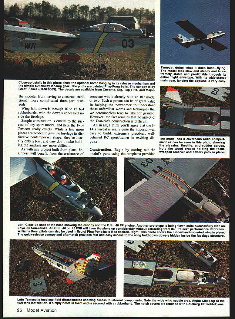
Stars-and-bars decals and additional graphics are available from Coverite, Sig Manufacturing, Top Flite Models, and Major Decals. The clear molded canopy is #CANF0003 from Great Planes Model Manufacturing Company. You can use a pair of Williams Bros. jet fighter pilots, or simply glue a pair of painted Ping-Pong balls under the lid.
Form and install the main gears. Use 1/2-in. nylon straps to hold them in place. Install the nose gear, using the steering arm supplied with the Goldberg Nose Gear set. Mount the wheels using 1/2-in. collars, then add the engine mount, engine, and fuel tank.
Line the perimeter of the wing saddle area on the fuselage with foam-backed tape to keep out fuel.
Radio installation
Install the Sullivan #503 throttle and nose gear pushrod guide tubes. Install the two 1/8-in. Lite Ply pushrod braces along the two 1/8-in. pushrod runs to keep the pushrods from flexing. Drill a 3/16-in. hole in each brace, slide them over the tube, then glue one to the fuselage crutch and the other to the fuselage bottom. Trim the ends of both tubes to extend 1/4 in. beyond bulkheads F-5, F-3, and the firewall.
Glue the forward 3/16-in. sq. maple servo rail in place. Note the locations of the rudder, elevator, and throttle servos on the plan. The rudder and throttle servo output arms must line up with the appropriate pushrod guide tubes. Use a servo to measure spacing for the location of the rear servo rail, and glue it in place. Again use the servo to locate and mark mounting holes for all three fuselage servos. Drill 1/8-in. pilot holes for the servo mounting screws into the rails at each mark. Install the three servos in the fuselage between the rails.
Complete the assembly of the Sullivan throttle and nose-gear pushrods. Attach the pushrods to the throttle lever, the nose-gear steering arm, and the appropriate servo output arms.
Make up the linkage rods for the elevator and rudders. Pushrod wires in the 5/32 x 12-in. size are available from Sullivan, Sig Manufacturing, Du-Bro Products, and Carl Goldberg Models. Thread a clevis onto each pushrod halfway down the threaded end, then use a Goldberg Pushrod Connector, Du-Bro EZ Connector, or a Z-bend to connect the pushrods at their servo ends.
Before connecting the elevator pushrod, slip a 1/8-in. Lite Ply F-6A pushrod guide over it. After the rod is connected to the elevator servo and control horn, glue the F-6A pushrod guide to F-6 to prevent the pushrod from flexing under flight loads.
An optional Vortec Manufacturing Bomb Release Mechanism and exploding-bomb installation is illustrated on the plan. The bomb doesn't actually explode, but its talcum-powder load makes a great visual effect when it hits a target. If desired, fit the parts for its installation now. A radio system of at least five channels will be required for the bomb-release option.
Cut the slot for the release mechanism into the floor of the fuselage. Glue two scraps of 1/8-in. Lite Ply to the inside of the floor at the mounting-screw locations. Drill two holes for the screws, and mount the release mechanism. Use double-sided tape to mount a fifth servo onto a piece of 1/8-in. Lite Ply scrap, then glue this onto the forward fuselage floor. Linkage from the servo to the release mechanism can be radio-dial cord or any non-stretching wire or string.
Cut two holes in the rear fuselage side for your radio system's on-off switch and charge jack. Locate these devices on the side of the model opposite the engine's exhaust. Plug the switch, elevator servo, throttle servo, rudder servo, and the aileron extension cable into the receiver (add a second extension cable for the bomb-release servo if used). Wrap the receiver and battery pack in 1/2-in. foam rubber, and install them in front of the servos, behind bulkhead F-5. Use enough foam to prevent these components from moving about inside the fuselage.
Glue two 1/8 x 1/2-in. spruce servo-mounting rails in place at the front and rear of the aileron-servo opening on the bottom of the wing. Drill 1/8-in. pilot holes for the mounting screws, and mount the servo in the wing. Make up the aileron pushrods in the same manner as the elevator and rudder pushrods. Plug the aileron servo into its extension cable from the receiver, and check for smooth operation of both ailerons.
Check the model's control-surface throw for sufficient travel and correct directions. For flight-training purposes, the elevator, rudders, and ailerons should all be set to 3/8 in. of travel in each direction. Nose-gear travel should be about 1/8 in. in each direction.
Confirm the model's center of gravity. With an empty fuel tank, the Tamecat's nose should tilt down one to two degrees when balanced from a point exactly one inch in front of the wing's main spar. Make absolutely sure of this before attempting to fly.
Flying
Flying is what the Tamecat does best. After successfully completing the customary range check, taxi her out, point the nose to the wind, and apply throttle. As the airplane reaches flying speed, a gentle touch of up elevator will lift it smoothly into the air. As with any new model, be ready to make minor corrections to the attitude, but mostly relax and enjoy one of the easiest-handling airplanes you will ever have the pleasure of flying. This model will go exactly where you aim it, displaying very gentle handling characteristics at every throttle setting.
Landings are what should be expected of any friendly sport plane—an extremely long power-down glide with no tendency toward tip-stall. Just point the Tamecat at a spot on the runway, throttle back, and glide onto it. Add power if you're too low, and be prepared to go around again if you're too steep. You'll really love this model on final approach.
One interesting feature of the Tamecat is that it will teach the student the use of elevator trim more efficiently than many other models. All airplanes need pitch trimming as their fuel tanks empty, but the Tamecat's long nose lets you see the trim changes a little better than most. Students can benefit greatly from this extra lesson, especially since the model teaches it so gently.
With the recommended control throws and CG position, the F-14 Tamecat will do all the required maneuvers in the trainer envelope, plus a few extras. Loops, lazy rolls, sustained inverted flight, stall turns, Immelmanns, and the split S are all a pleasure to perform. The model stays right on target and never gets squirrely. Slow flybys are simply magnificent.
If a little more aerobatic agility is desired, move the center of gravity back an inch (balance the model from the main spar), increase the aileron and elevator rates, and try the Tamecat with the rest of the pack. This design will teach the very basics, yet grow along with a flier as he progresses through mild aerobatics instruction.
This sport/training model meets my design goals and even exceeds them. It mimics a jet-fighter appearance, yet sacrifices none of the friendly flying stability and easy-building qualities of today's top-notch trainers. The first time you see this model in the air, those twin wingtips and long nose will prove that a well-behaved model can still sport a fiercely aggressive image. Sure, the Tamecat only resembles that supersonic, ducted-fan-powered, accurately scaled-down F-14. It's all bluff, but underneath the façade this is no awkward ugly duckling. This is a sport/trainer that looks as if someone might actually want to own it. Just wait until your flying buddies check it out. One ferocious-looking Tamecat, on the prowl for a target... "Purr-r-r-r!"
Transcribed from original scans by AI. Minor OCR errors may remain.

