
Taming the Autogiro
Editor's Note
Scientific reporting was one of the founding missions of AMA, and it is not surprising that among us are many inquisitive minds who delve deeply into obscure matters to open new worlds for us. With pleasure, AMA presents one such project report.
Why is it that model autogiros invariably have wings? If RC helicopters work properly, why shouldn't autogiros? Now they can—thanks to the author's painstaking development of the proper "head."
- William J. Kuhnle
Introduction
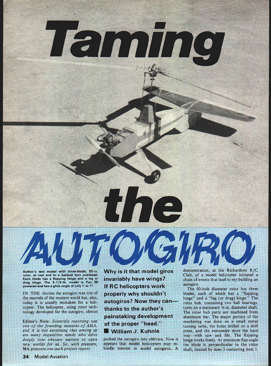
In the thirties the autogiro was one of the marvels of the modern world but, alas, today it is usually mistaken for a helicopter. The helicopter, using rotor technology developed for the autogiro, almost pushed the autogiro into oblivion. Now it appears that model helicopters may rekindle interest in model autogiros. A demonstration at the Richardson R/C Club of a model helicopter initiated a chain of events that led to my building an autogiro.
About six months of experimentation were required to develop it into a flyable aircraft. Much more work remains, for it is not yet an easy-to-fly model. The configuration, areas, and moments required for a good flying fixed-wing plane are well known. Unfortunately (or fortunately, if you like to experiment), the recipe for a successful autogiro is not common knowledge.
Rotor Hub and Hinges
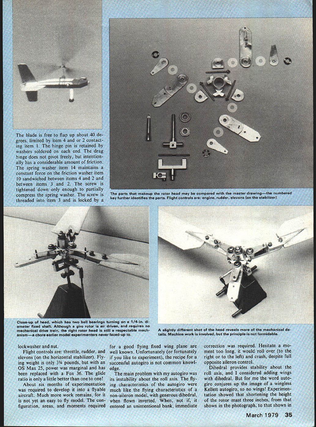
The 50-inch diameter rotor has three blades, each of which has a flapping hinge and a lag (or drag) hinge. The rotor hub, containing two ball bearings, turns on a stationary 1/4-inch diameter shaft. The rotor hub parts are machined from aluminum bar. The major portion of the machining was done on a small metal turning lathe, the holes drilled on a drill press, and the remainder done the hard way—with saw and file.
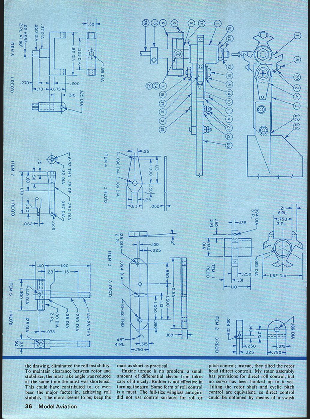
The flapping hinge works freely. At minimum flap angle the blade is perpendicular to the rotor shaft, limited by item 3 contacting item 1. The hinge pin is retained by washers soldered on each end.
The drag hinge does not pivot freely but intentionally has a considerable amount of friction. The spring washer (item 14) maintains a constant force on the friction washer (item 10) sandwiched between items 3 and 2. The screw is tightened down only enough to partially compress the spring washer. The screw is threaded into item 3 and is locked by a lockwasher and nut.
Flight Controls and Performance
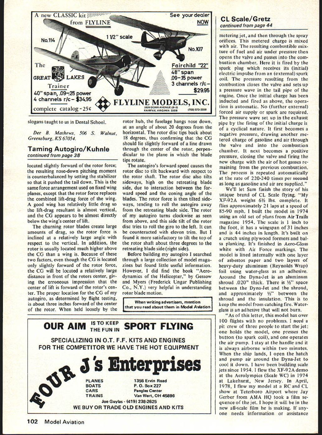
Flight controls are: throttle, rudder, and elevons (on the horizontal stabilizer). Flying weight is only 3 3/4 pounds. With an OS Max .25, power was marginal and has been replaced with a Fox .36. The glide ratio is only a little better than one to one!
Engine torque is no problem; a small amount of differential elevon trim takes care of it nicely. Rudder is not effective in turning the autogiro. Some form of roll control is a must. Full-size wingless autogiros did not use control surfaces for roll or pitch control; instead they tilted the rotor head (direct control). My rotor assembly has provisions for direct roll control, but no servo has been hooked up to it yet. Tilting the rotor shaft and cyclic pitch control are equivalent, so direct control could be obtained by means of a swashplate.
Stability and Control
The main problem with my autogiro was its instability about the roll axis. The flying characteristics of the autogiro were much like those of a non-aileron model with generous dihedral when flown inverted. When, not if, it entered an unintentional bank, immediate correction was required. Hesitate a moment too long and it would roll over (to the right or to the left) and crash, despite full opposite aileron control.
Dihedral provides stability about the roll axis, and I considered adding wings with dihedral. But for me the word autogiro conjures up the image of a wingless Kellett autogiro, so no wings! Experimentation showed that shortening the height of the rotor mast three inches, and reducing the mast rake angle to maintain clearance between rotor and stabilizer, eliminated the roll instability. This could have contributed to, or even been the major factor in, achieving roll stability. The moral seems to be: keep the mast as short as practical.
Engine torque is countered by elevon trim. The rotor force is located slightly forward; the rotor force resulting in a nose-down pitching moment is counterbalanced by setting the stabilizer so it pushes the tail down.
Center of Gravity and Rotor Forces
The proper location of the CG on an autogiro is determined by flight testing. On my autogiro the CG is about three inches forward of the center of the rotor. When held loosely at the rotor hub, the fuselage hangs nose down at an angle of about 20 degrees to the horizontal. The rotor disc tips back about 18 degrees, thus confirming the CG should lie slightly forward of the line drawn through the center of the rotor perpendicular to the plane of the blade tips.
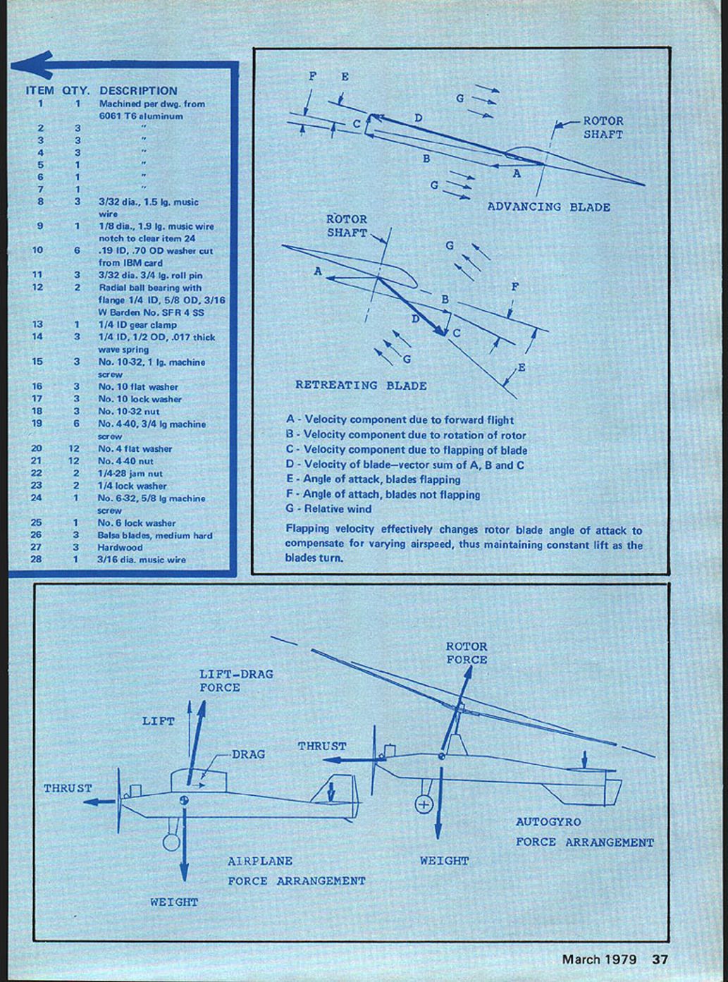
A good fixed wing has relatively little drag, so the lift-drag resultant is almost vertical and the CG appears almost directly below the wing's center of lift. Churning rotor blades create large amounts of drag; the rotor force is inclined at a relatively large angle with respect to the vertical. In addition, the rotor is usually located much higher above the CG than a wing. Because of these two factors, though the CG may be located slightly forward of the rotor force, the CG will be located a relatively large distance in front of the rotor's center, giving the erroneous impression that the center of lift is forward of the rotor's center.
As autogiros gain forward speed, the rotor disc tilts backward with respect to the rotor shaft. The rotor disc also tilts sideways on the retreating-blade side because of the interaction between forward speed and the coning angle of the blades. The rotor force is tilted sideways, tending to roll the autogiro away from the retreating-blade side. If the rotor of an autogiro turns clockwise as seen from above, the side tilt of the rotor disc tries to roll the giro to the left; this can be counteracted by trim. I found a satisfactory trim to be a tilt of the top of the rotor shaft about three degrees toward the retreating-blade side (the right side).
Rotor Blade Aerodynamics
Understanding rotor blade motion was aided by the book Aerodynamics of the Helicopter by Gessow and Myers.
Velocity and angle components for a rotor blade:
- A - Velocity component due to forward flight
- B - Velocity component due to rotation of rotor
- C - Velocity component due to flapping of blade
- D - Velocity of blade — vector sum of A, B and C
- E - Angle of attack, blades flapping
- F - Angle of attack, blades not flapping
- G - Relative wind
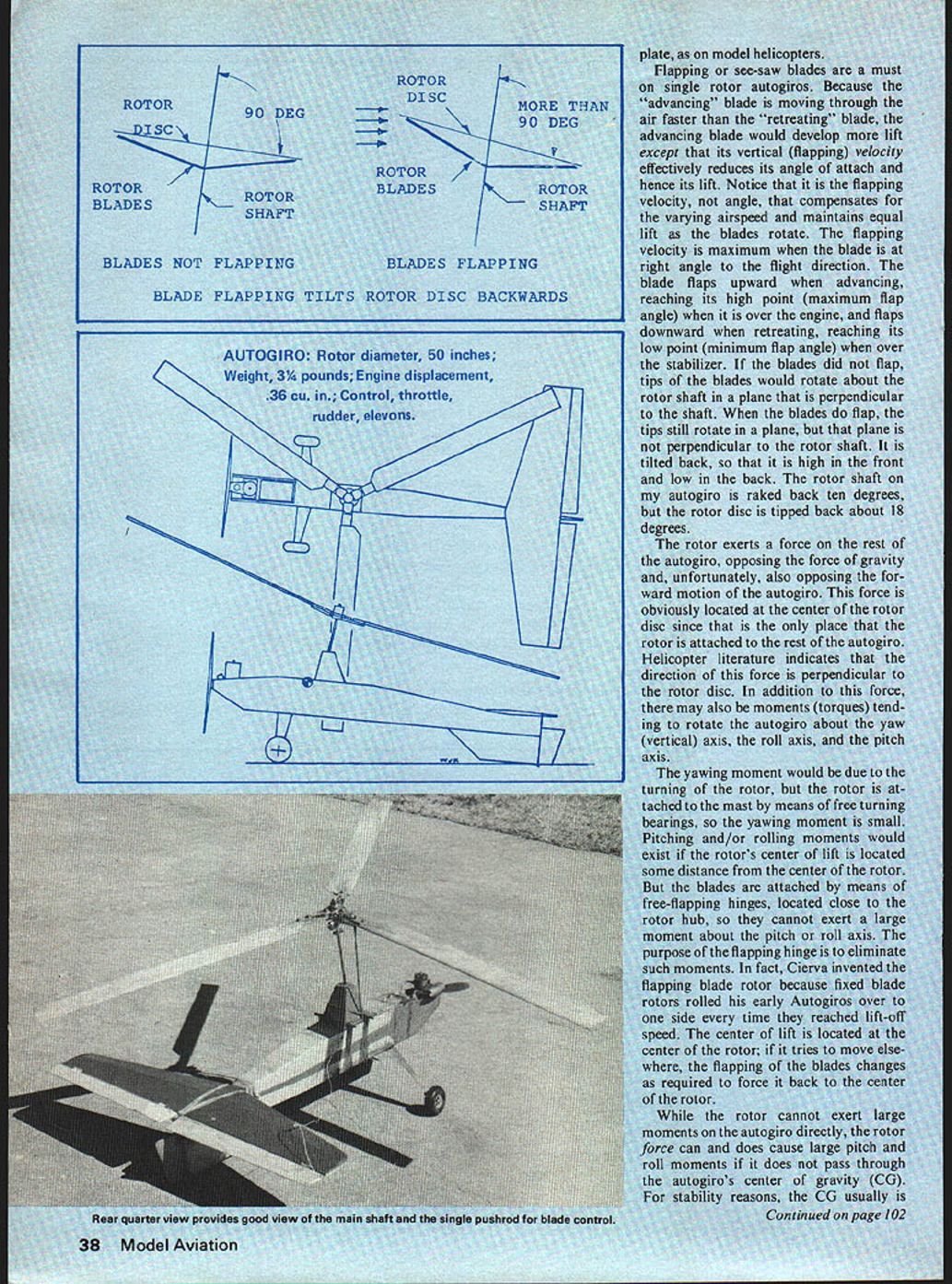
Flapping velocity effectively changes the rotor blade angle of attack to compensate for varying airspeed, thus maintaining constant lift as the blades turn. Flapping or see-saw blades are a must on single-rotor autogiros. Because the advancing blade is moving through the air faster than the retreating blade, the advancing blade would develop more lift except that its vertical (flapping) velocity effectively reduces its angle of attack and hence its lift.
Notice that it is the flapping velocity, not flap angle, that compensates for the varying airspeed and maintains equal lift as the blades rotate. The flapping velocity is maximum when the blade is at right angle to the flight direction. The blade flaps upward when advancing, reaching its high point (maximum flap angle) when it is over the engine, and flaps downward when retreating, reaching its low point (minimum flap angle) when over the stabilizer.
If the blades did not flap, the tips of the blades would rotate about the rotor shaft in a plane that is perpendicular to the shaft. When the blades do flap, the tips still rotate in a plane, but that plane is not perpendicular to the rotor shaft. It is tilted back, high in the front and low in the back. The rotor shaft on my autogiro is raked back ten degrees, but the rotor disc is tipped back about 18 degrees.
Moments and Stability Considerations
The rotor exerts a force on the rest of the autogiro, opposing gravity and also opposing forward motion. This force is located at the center of the rotor disc since that is the only place the rotor is attached to the autogiro. Helicopter literature indicates that the direction of this force is perpendicular to the rotor disc.
In addition to this force, there may be moments (torques) tending to rotate the autogiro about the yaw (vertical) axis, the roll axis, and the pitch axis. The yawing moment would be due to the turning of the rotor, but the rotor is attached to the mast by free-turning bearings, so the yawing moment is small.
Pitching and rolling moments would exist if the rotor's center of lift is located some distance from the center of the rotor. But the blades are attached by free-flapping hinges located close to the rotor hub, so they cannot exert a large moment about the pitch or roll axis. The purpose of the flapping hinge is to eliminate such moments. In fact, Cierva invented the flapping blade rotor because fixed blade rotors rolled his early autogiros over to one side every time they reached lift-off speed. The center of lift is located at the center of the rotor; if it tries to move elsewhere, the flapping of the blades changes as required to force it back to the center of the rotor.
While the rotor cannot exert large moments on the autogiro directly, the rotor force can and does cause large pitch and roll moments if it does not pass through the autogiro's center of gravity. For stability reasons, the CG is usually located slightly forward of the rotor force; the resulting nose-down pitching moment is counterbalanced by setting the stabilizer to push the tail down.
References
- Gessow, A., & Myers, G. (Aerodynamics of the Helicopter). Frederick Ungar Publishing Co., N.Y.
Transcribed from original scans by AI. Minor OCR errors may remain.

