
Taperwing
For several years the 1/2A pylon‑racing circuit has been dominated by one or two designs. Now there's a new name to add to the list, and it's already consistently beating the planes that have led the pack for so long.
For the pylon racer who wants the best, for the RC flier who wants to get into pylon racing, or for anyone who wants to see what a Cox Tee Dee can really do, the Taperwing is an exciting possibility.
Designed in collaboration with J. E. Albritton, this 1/2A racer is faster than the GLH and smoother than the Undertaker. Thanks to its minimal frontal area and a tapered wing and fuselage, this single‑aileron model achieves 90+ mph speeds that stretch the limits of standard performance—yet it still complies with AMA rules.
RC pylon racing is a good test of several key facets of RC modeling: airframe, propulsion, piloting, and organization. The value of the 1/2A subcategory is that it simplifies the event and makes it possible for anyone to compete. The Taperwing extends the advantage further by incorporating concepts that sharpen your competitive edge:
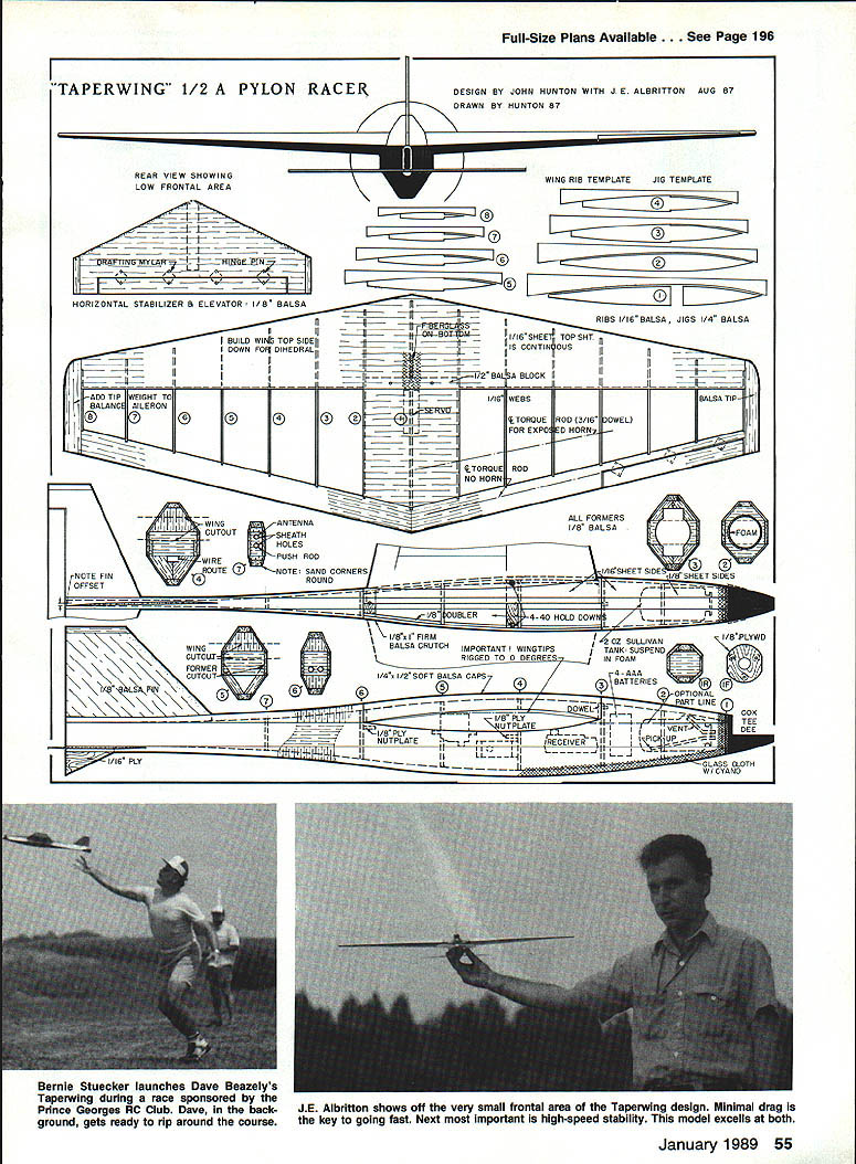
- Airframe: the lowest possible frontal area within the rules. Both wing and fuselage are tapered. The single aileron helps hold up the nose when entering a turn. The tapered wing planform improves efficiency in turns. Incidence, twist, and offsets are used for greatest aerodynamic efficiency.
- Propulsion: getting the most out of an engine is emphasized (see the engines, propellers, and fuels sections).
- Piloting: on a tight 1/2A pylon course the Taperwing is easier to fly than twitchier models. Its elongated configuration gives steady, stable flight and makes the airplane easy to launch and a good racing trainer.
- Organization: efficient pit operations and consistent equipment increase overall reliability (see reliability and organization).
The design has gone through iterative development and has two seasons of racing behind it. Although engineered to AMA rules, the shapes and proportions are unique.
Evidence of the design's inherent stability came during a race in Reston, VA. In the first heat a Taperwing, while lapping a slower model, collided with it; one complete side of the horizontal stabilizer and elevator sheared off flush with the fuselage. Even with only half the stabilizer, the Taperwing continued to fly and went on to win that heat and the remaining races.
AMA rules (summary for 1/2A racing planes)
- Minimum weight: 20 oz. (The Taperwing can be built under 16 oz.)
- Minimum wing area: 200 sq in
- Wing root depth: 7/8 in.
- Fuselage width: 2.25 in.
- Fuselage depth: 3.50 in.
Performance assumptions and calculations
The following assumptions are made for the calculations below:
- Weight = 20 oz. = 1.25 lb. = W
- Air density = 0.00238 slug/ft3 = a
- Velocity of Taperwing = 90 mph = 132 ft/s = Vt
- Frontal area of Taperwing = 22.6 sq in = 0.157 sq ft = St
- Frontal area of GLH = 33.5 sq in = 0.233 sq ft = Sg
- Horsepower output of Tee Dee = 0.1 hp = HPR
Calculating coefficient of drag (Cd) for the Taperwing:
- Power relation: HPR = D * V / 375
- 0.1 = Dt × 132 / 375
- Drag (T) Dt = 0.284 lb.
Using Dt = 0.5 × rho × V^2 × Cd × S:
- 0.284 = 0.5 × 0.00238 × 132^2 × Cd × 0.157
- Cd (T) = 0.0872
Using this Cd value for the GLH and computing drag:
- Dg = 0.5 × 0.00238 × V^2 × 0.0872 × 0.233
- Dg = 0.000241 × V^2
Solving for velocity with HPR = 0.1:
- 0.1 = 0.000241 × V^3 / 375
- V (GLH) ≈ 115.9 ft/s ≈ 79 mph
Conclusion: with engines of equal horsepower, the Taperwing will do about 90 mph while a GLH will do about 79 mph. These are simplified approximations but reflect actual race results, where the Taperwing has proven considerably faster.
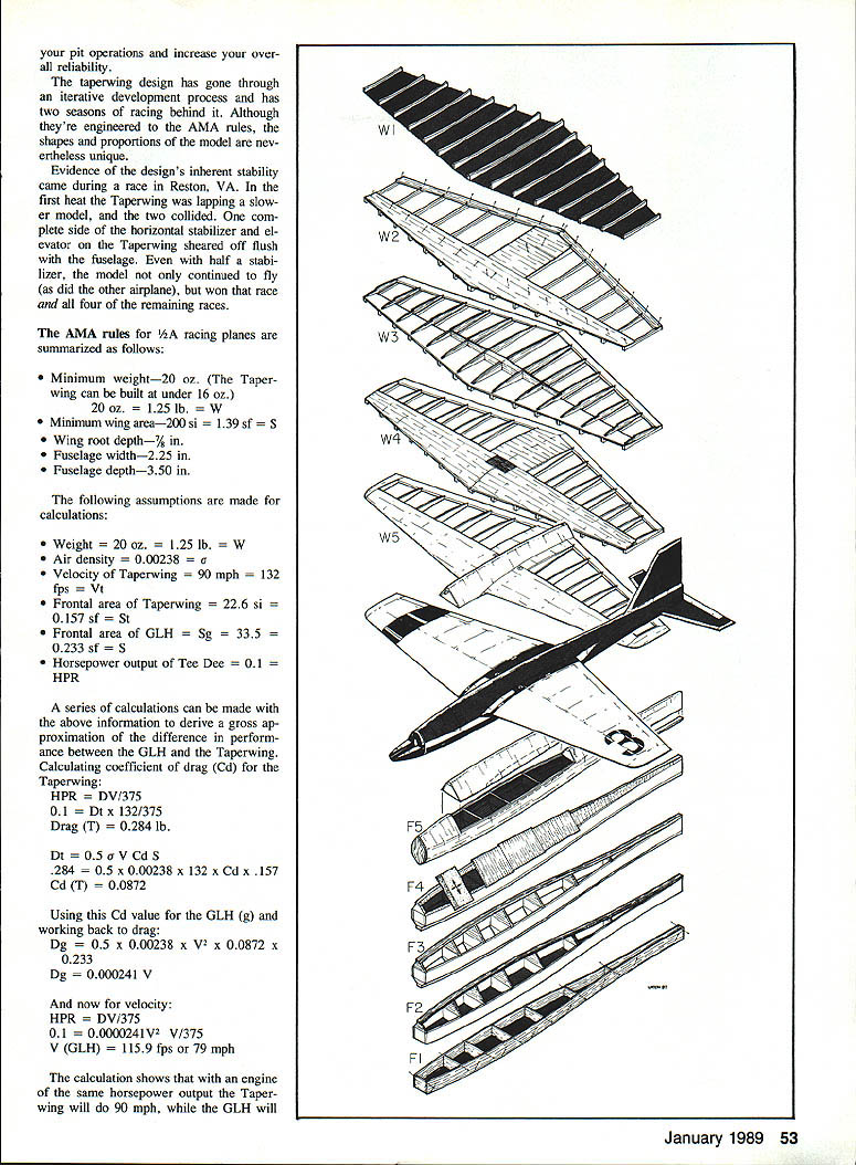
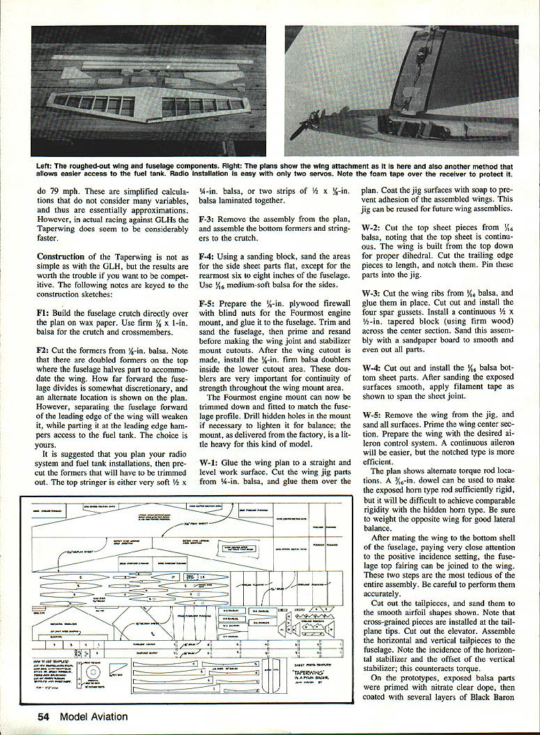
Construction
The Taperwing is simple to build. If GLH‑competitive results are worth the effort, follow these notes keyed to the construction sketches.
Fuselage
- F1: Build the fuselage crutch directly over the plan on wax paper. Use firm 1/8 × 1 in. balsa crutch crossmembers.
- F2: Cut formers from 1/8‑in. balsa. Note doubled formers on the top fuselage halves to accommodate the wing. The far‑forward wing location is somewhat discretionary; an alternate location is shown on the plan. However, separating the fuselage at the forward leading edge of the wing will weaken the parting. Use a 1/4‑in. balsa leading edge, or two strips of 1/2 × 1/8‑in. balsa laminated together.
- F3: Remove the assembly from the plan and assemble the bottom formers and stringers to the crutch.
- F4: Using a sanding block, sand the areas for the side sheet parts flat, except for the rearmost six to eight inches of the fuselage. Use 1/16‑in. medium‑soft balsa for the sides.
- F5: Prepare the 1/8‑in. plywood firewall with blind nuts for the Fourmost engine mount, and glue it to the fuselage. Trim and sand the fuselage, then prime and resand before making the wing join and stabilizer mount cutouts. After the wing cutout is made, install 1/8‑in. firm balsa doublers inside the lower cutout area. These doublers are very important for continuity of strength throughout the wing mount area.
- The Fourmost engine mount can now be trimmed and fitted to match the fuselage profile. Drill hidden holes in the mount if necessary to lighten it for balance; the mount as delivered is a little heavy for this kind of model.
Wing
- W1: Glue the wing plan to a straight, level work surface. Cut wing jig parts from 1/4‑in. balsa and glue them over the plan. Coat the jig surfaces with soap to prevent adhesion. This jig can be reused.
- W2: Cut the top sheet pieces from 1/8‑in. balsa; note that the top sheet is continuous. The wing is built from the top down for proper dihedral. Cut and notch the trailing edge pieces and pin these parts into the jig.
- W3: Cut the wing ribs from 1/8‑in. balsa and glue them in place. Cut out and install 1/8‑in. spar gussets. Install a continuous 1/4 × 1/8‑in. tapered block (using form wood) across the center section. Sand the assembly to smooth and even all parts.
- W4: Cut out and install the 1/16‑in. balsa bottom sheet parts. After sanding the exposed surfaces smooth, apply filament tape as shown to span the sheet joint.
- W5: Remove the wing from the jig and sand all surfaces. Prime the wing center section. Prepare the wing with the desired aileron control system—a continuous aileron is easier, but the notched type is more efficient.
Notes on aileron torque rods: the plan shows alternate torque rod locations. A 3/32‑in. dowel can be used to make an exposed horn‑type rod sufficiently rigid. Achieving comparable rigidity with the hidden horn type is more difficult. Be sure to weight the opposite wing for lateral balance.
After mating the wing to the bottom shell of the fuselage, paying very close attention to the positive incidence setting, the fuselage top fairing can be joined to the wing. These two steps are the most tedious of the assembly; perform them accurately.
Tail and controls
- Cut out the tailpieces and sand them to the smooth airfoil shapes shown. Note cross‑grained pieces installed at the tailplane tips. Cut out the elevator. Assemble the horizontal and vertical tailpieces to the fuselage.
- Note the incidence of the horizontal stabilizer and the offset of the vertical stabilizer; this counteracts torque.
Covering and finish
- On prototypes, exposed balsa parts were primed with nitrate clear dope, then coated with several layers of Black Baron.
- Use heat‑shrink covering for the wing panels. Select colors that are very light on top and dark on the bottom so you can rapidly tell upright from inverted. Use a distinctive top scheme for easy recognition by judges.
- Suspend the fuel tank in foam to prevent fuel frothing. One AMA rule mandates a fuel shutoff; locating the fuel pickup near the bottom of the tank allows the model to be inverted in flight to starve the engine.
- Many hinging systems work; Mylar drafting sheet hinges installed with cyanoacrylate glue (CyA) are simple and effective. Insert pins to secure them.
- For elevator actuation, a goldenrod‑type pushrod system is recommended. Install a piece of pushrod inner sheath to run the antenna to the tail. Install radio gear.
- Check the balance point carefully. Add ballast if necessary for correct control response. Check lateral balance—unequal wing weight will cause roll tendencies through turns.
Engines
Stock
- If AMA rules are followed, use stock engines. Due to manufacturing tolerances, you can sometimes get higher performance by mixing pistons and cylinders from several engines and testing combinations. Work with the glow plug to find the highest practical compression ratio (by removing washers to increase compression) that still maintains good needle‑valve sensitivity and ease of starting.
Semistock
- Kustom Kraftsmanship (KK) sells a fine, powerful engine with dimensional improvements, a fine‑thread needle valve, and optional drilled venturi and pressure‑tapped backplate. The KK engine and the Taperwing make a fine team.
Modified engines
- Mild: Some clubs allow mild mods to increase reliability. These include using a 72‑turn needle valve from KK and a pressure fuel system that employs a pressure‑tapped backplate.
- Wild: Drilling the venturi to 3/32 in. with a pressure fuel system yields appreciable power increase. Tapering transfer ports (special machining) is another performance mod. Contact J. E. Albritton for details.
Propellers
- Stock: Cox 5 × 3 prop works best. This prop has an actual pitch of over 4 in.
- Semistock: 4‑3/4 × 3 from Kustom Kraftsmanship.
- Sorta‑stock: An Albritton carbon fiber special prop for V2A is available in limited quantities; write for details. This was the best prop known at the time of writing.
- Nonstock: Remove 1/2 in. from the entire leading edge of a Cox 5 × 3, sand the airfoil back on top, and shorten it to 4‑3/4 in.
Note: For optimal engine performance in the air, choose a prop that allows the engine to exceed 23,000 rpm on the ground.
Fuels
- Cox racing fuel is hard to beat; Cox engines in particular run well on it. No other brand of fuel with under‑30% nitro is recommended.
Reliability and organization
- Follow KISS: Keep It Simple, Stupid. Plan what equipment you need and use the same equipment every time you fly. Repetition builds reliability.
- Flying: The Taperwing is designed for pylon racing and turns very tightly. Keep it within sight—its low frontal profile makes it difficult to see at a distance. If the nose tends to rise on a turn, check transmitter stick alignment—chances are it is not pulled straight back. For smoother, faster pylon performance, set control throws to the minimum required.
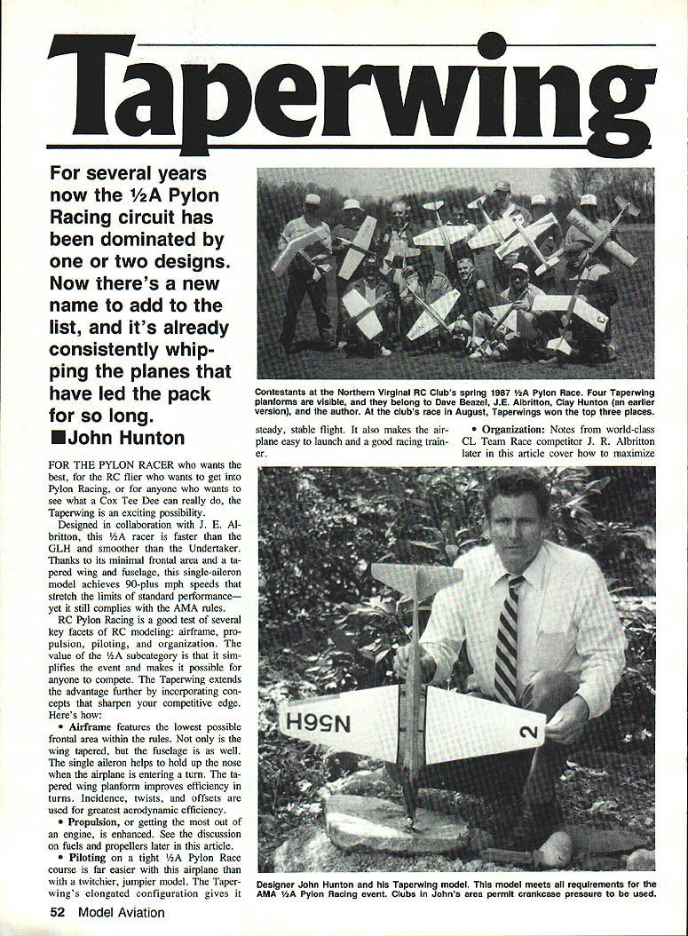
At the Northern Virginia RC Clubs' spring 1987 1/2A pylon race, four Taperwings were visible (owners: Dave Beazell, J. E. Albritton, Clay Hunton, and an earlier version by the author). At the club's August race, Taperwings took the top three places. Clubs in the author's area permit crankcase pressure to be used in pit operations to increase reliability.
Contacts
Kustom Kraftsmanship P.O. Box 3010 Fallbrook, CA 92028
J. E. Albritton 503 Orrin Dr. Vienna, VA 22180
Designer: John Hunton (with J. E. Albritton)
Transcribed from original scans by AI. Minor OCR errors may remain.

