
Taylorcraft
By Brad Shepherd
It was one man's dream to turn a general aviation aircraft of the 1930s into an aerobatic machine suitable for national competition. His success is celebrated in the clipped-wing T‑Craft, one of the two versions presented here. These models are for four-channel controls and .40 engines.
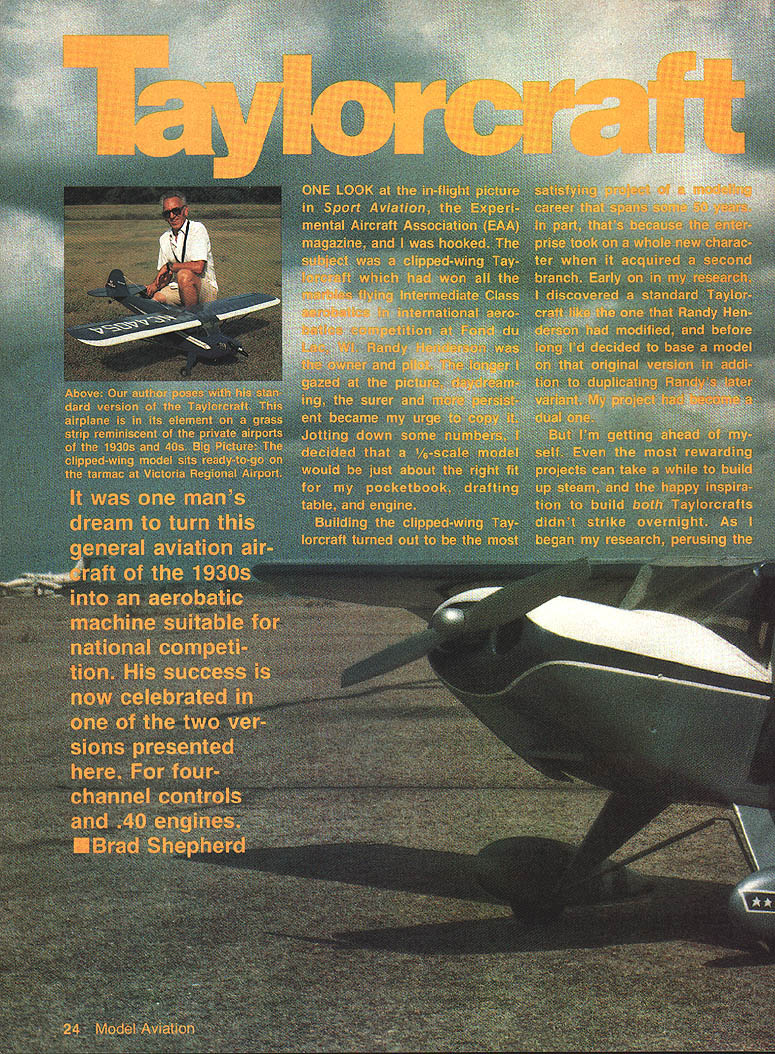
One look at the in-flight picture in Sport Aviation, the Experimental Aircraft Association (EAA) magazine, and I was hooked. The subject was a clipped‑wing Taylorcraft that had won top honors flying Intermediate Class aerobatics at Fond du Lac, WI. Randy Henderson was the owner and pilot. The longer I gazed at the picture, the stronger became my urge to copy it. Jotting down some numbers, I decided that a 1/6‑scale model would fit my pocketbook, drafting table, and engine.
Building the clipped‑wing Taylorcraft turned out to be the most satisfying project of a modeling career spanning some 50 years. The project took on a second branch when I discovered a standard Taylorcraft like the one Randy had modified. Before long I decided to base a model on that original version in addition to duplicating Randy's variant—my project became a dual one.
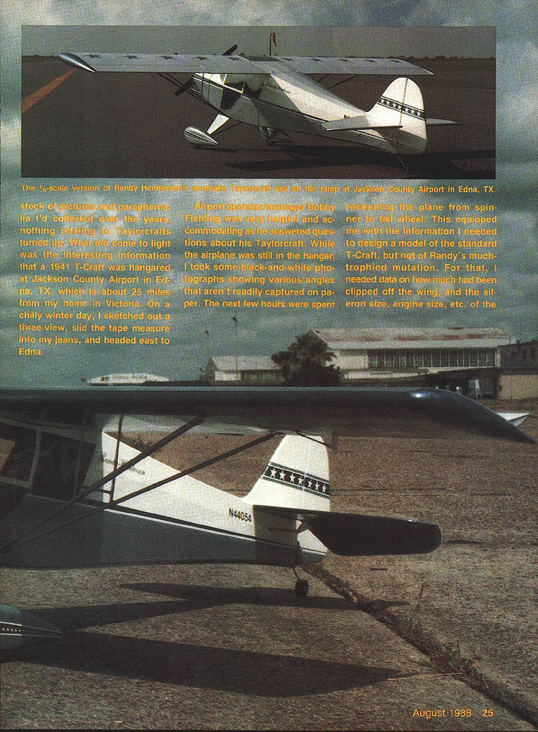
Early in my research I learned a 1941 T‑Craft was hangared at Jackson County Airport in Edna, TX, about 25 miles from my home in Victoria. On a chilly winter day I sketched a three‑view, slid the tape measure into my jeans, and headed to Edna.
Airport operator/manager Bobby Fielding was very helpful. While the airplane was still in the hangar I took black‑and‑white photographs and measured the plane from spinner to tailwheel. That gave me the information I needed to design a model of the standard T‑Craft, but not of Randy's modification. To get the clipped‑wing data I wrote the EAA for Randy's address. Meanwhile I used my sketches, dimensions, and photos of the unmodified 1941 Taylorcraft to begin building.
I made an initial rough drawing and built a fuselage for the hangar‑stock model, solving center‑section problems as I went. About the time I finished a second version of the fuselage, I received photos and dimensions from Randy. The photos helped finish the model under way; the dimensions enabled me to proceed with the clipped‑wing version.
After building the 1/2‑scale model of Randy's airplane, I visited Frisco, TX to meet the man behind the metamorphosis. We stayed with a son and his family in Dallas. The four hours I spent with Randy were some of the most enjoyable of my life. Randy is a gracious, engaging individual who made me feel at home. During our visit I photographed my model with Randy's prototype, examined logbooks, and learned more about the winnings that his originality and competence had earned him. Randy also told vivid stories of his progression from young pilot to accomplished aerobatics enthusiast.
Randy worked his way through two years of college, then joined the Air Force and served as a medic. He earned his pilot's license while stationed in England. After discharge he returned to Mississippi, obtained his commercial rating, and landed a job as first officer on DC‑3 aircraft with a cargo company flying out of Memphis, TN. Starting with just 380 hours of flying time, in three years he'd accumulated over 3,000 hours flying day and night in all kinds of weather—and surviving 13 engine failures.
In 1978 Randy achieved a longtime ambition when his former commercial flight instructor helped him acquire a B‑737 rating at Piedmont Airlines. He later joined Southwest Airlines and is now, at 38 years young, a captain flying out of Love Field in Dallas.
While pursuing his career, Randy was bitten by the aerobatics bug after watching Charlie Hilliard and Mary Gaffney win the 1972 International Aerobatics Championships (IAC). In 1979 he did his first roll at 5,000 ft in a 1947 clipped‑wing Cub he had purchased that year. Shortly afterward he started flying his Cub in air show work with J.D. Gauthright.
In 1980 Gauthright purchased a partially refurbished Taylorcraft NC‑44054, intending to use it for air shows. Randy subsequently bought the Taylorcraft and decided to upgrade it for IAC contests. Three years of work later, the championed T‑CRAFT was unveiled and test‑hopped on Randy's birthday in August 1983. During 1984–85 the T‑Craft captured Sportsman category trophies. Randy advanced to Intermediate level contests and never placed lower than second in 1985 and 1986 events at Sherman, TX. In 1986 he became the U.S. Intermediate Champion. He also won the 1987 Lone Star Championships at Denton, TX, and the Houston Gulf Coast Championships at Jackson County Airport in Edna.
Randy is currently developing a beefed‑up 250‑hp midwing Laser variation for Advanced competition. Having watched him fly his Intermediate routine at the "Cotton Patch Aerodrome"—Randy's front yard—I expect he will become World Champion one day. Every maneuver of his routine was almost picture perfect inside the box.
The NC‑44054 was rolled out of the Taylorcraft factory at Alliance, OH, in October 1946 for final inspection and runup of the 65‑hp Continental. Its airworthiness certificate followed a 35‑minute test flight a few days later. The Taylorcraft spent much of its life around the upper central U.S. until J.D. Gauthright purchased it 34 years after its debut.
After Randy bought the T‑Craft, he installed wings clipped to 28 ft with squared tips, built balances into the aileron ends, set up rudder pedals so the plane could be flown from either side or the middle in competition, installed a 180‑hp Lycoming and a smoke system for air show work, added Pitts‑style wheel pants and cowlings, and doubled the tail wires.
On a later visit Randy gave me a ride in the T‑Craft. He promised a "no surprises" ride around the pasture—and delivered the best airplane ride of my life. Vibration was practically nonexistent, indicating the engine and prop were well balanced, and the 180 horses made it perform. Randy let me fly it from the passenger seat; the airplane was set up so perfectly that the smallest control movement commanded an instant response.
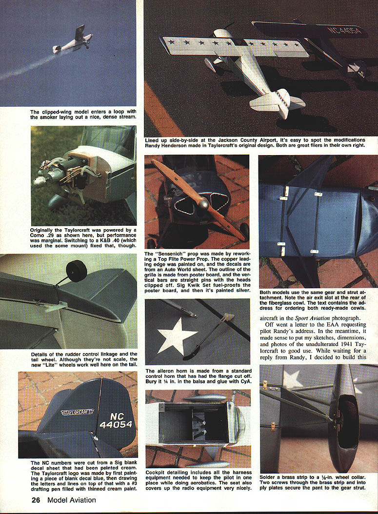
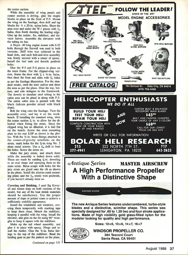
I first flew my T‑Craft model from a grass strip on a ranch I call Utopia. Powered initially by a Com .29 with a smoke system and a Master Airscrew 9 x 6 prop, the model had only marginal performance and was nose‑heavy. A 10 x 4 black magnum prop helped only slightly. Back home I substituted a K&B .40 engine and moved the radio gear aft. The K&B .40 provided the performance needed.
After adjusting the trim and control throws (adding right thrust, less rudder, and more aileron), performance improved dramatically. Leon Folsom photographed a banquet of maneuvers with the smoker going: snaps‑on‑loops, square loops, inverted loops, slow rolls and point rolls, knife‑edge flight, outside loops and snaps. While attempting a slip on landing approach I nearly wrecked it, but recovered—those landings will take practice!
The T‑Craft proved itself, and I put it aside until the Houston Gulf Coast IAC Championships at Jackson County Airport in Edna. Randy was competing and wanted to see the model fly and get some pictures for an article in Sport Aerobatics. With only one radio, I removed the gear from the clipped wing and installed it in the standard NC‑44054 T‑Craft for test flying.
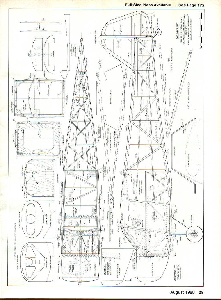
I also flew the model at the Waco Hot Macs field while on a camping trip at Lake Waco with my family. After waiting for winds to subside we flew the model with an O.S. .40 four‑stroke and a Master Airscrew 11 x 6 prop. The rudder initially responded backwards (operator error), but after reversing a servo the T‑Craft floated off. The model weighs less than five pounds and has a 765‑sq. in. area. Powered by the four‑stroke and the 11 x 6 prop, it attains a virtually scale speed and performs maneuvers at scale‑like speeds. The model snaps and rolls beautifully, and is a real joy in the air. Rudder coordination is critical for rolls and straight flight.
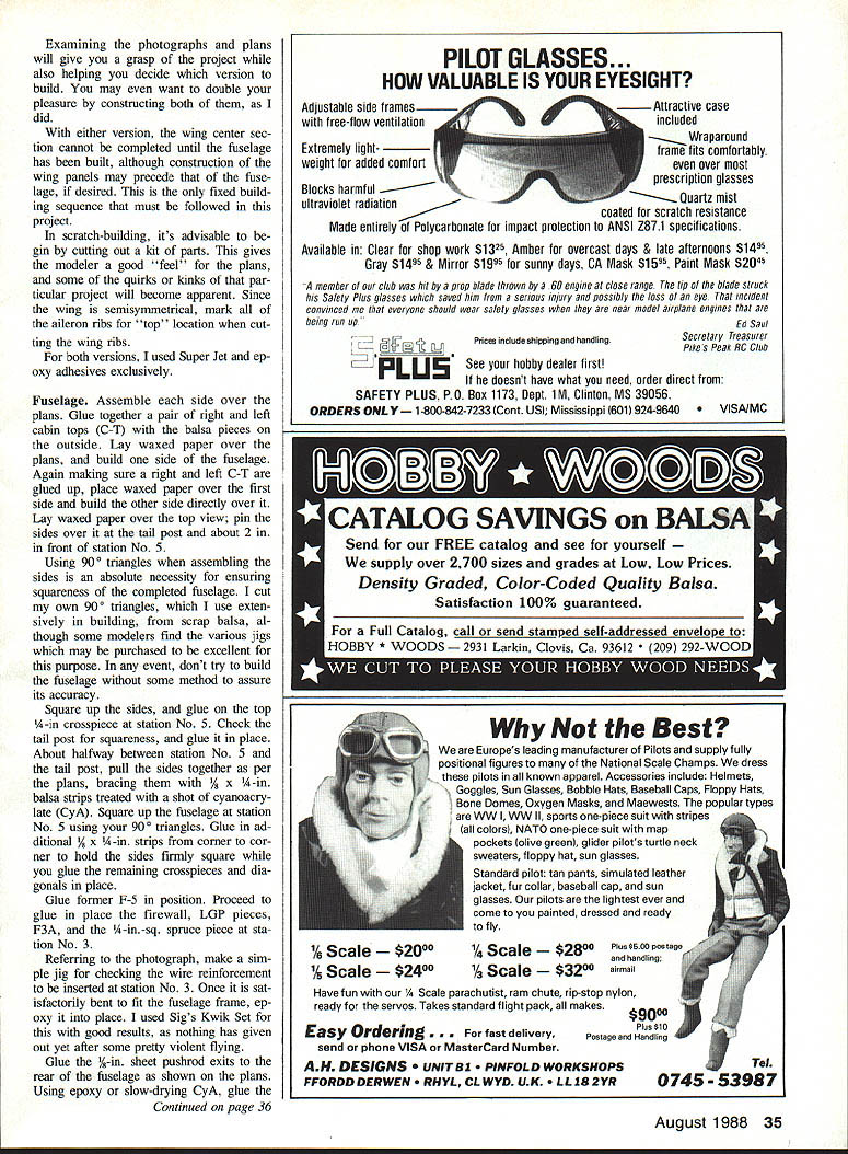
Both my hangar‑stock and clipped‑wing models use stick‑and‑tissue construction. This method allowed me to craft lighter, stronger models almost as quickly as the balsa sheet models I’d built for many years. Examining the photographs and plans will help you decide which version to build—or build both, as I did.
With either version, the wing center section cannot be completed until the fuselage has been built, although wing panels may be built first if desired. This is the only fixed building sequence you must follow.
In scratch‑building, begin by cutting out a kit of parts. This gives a feel for the plans and reveals quirks of the project. Since the wing is semisymmetrical, mark all aileron ribs for "top" location when cutting ribs. I used Super Jet and epoxy adhesives exclusively.
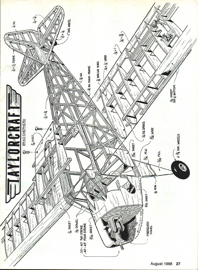
Materials and hardware (selected)
- 1/4 x 1/4 frame stock
- 1/16 sheet
- 1/8 sheet
- 1/8 sq. main frame
- 1/8 balsa ribs
- 1/4 x 1/8 stock
- 1/8 sq. spars
- 3/32 sheet top & bottom
- 3/32 sheet
- 3/32 dowel
- Engines: 30–40 two‑stroke, 40–45 four‑stroke (recommended)
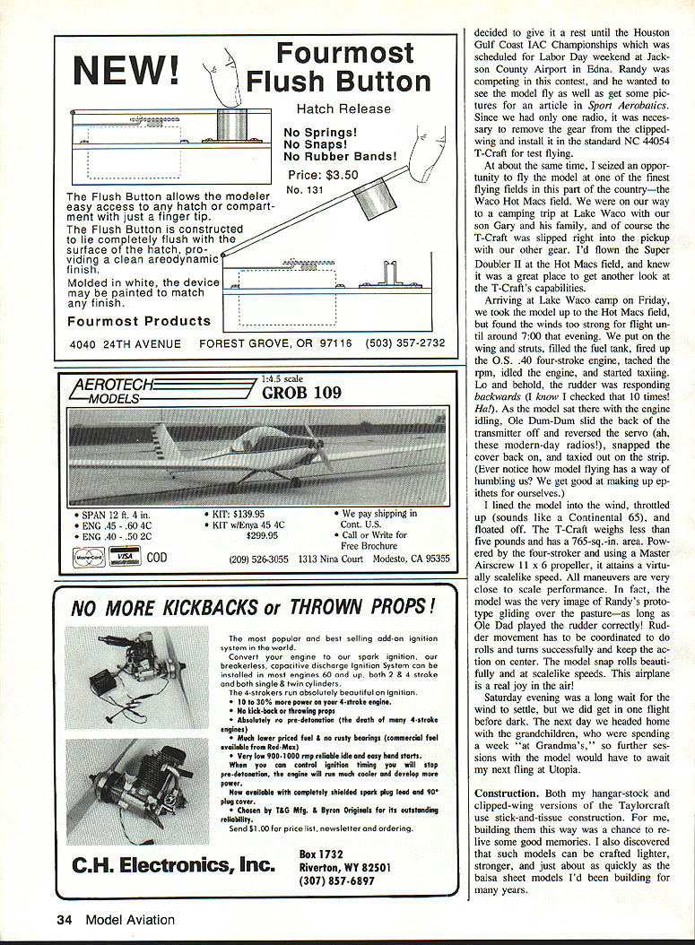
- Fiberglass cowl
- 3/16 fill
- 3/32 wire
- Wheels: 2‑3/8 in. dia. wheels or 1 in. dia. off‑the‑shelf hangar‑stock wheel
- Hayes .40 long engine mount (used) with 6‑32 bolts through the firewall
Construction
Fuselage
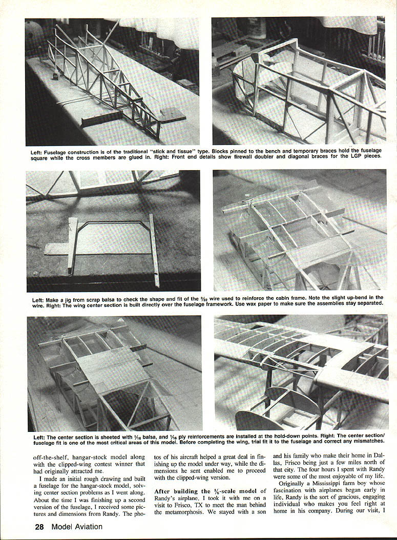
Assemble each side over the plans. Glue together a pair of right and left cabin tops (C‑T) with the balsa pieces on the outside. Lay waxed paper over the plans. Build one side of the fuselage; make sure a right and left C‑T are glued up, place waxed paper over the first side, and build the other side directly over it.
Lay waxed paper over the top view and pin the sides over it at the tail post and about 2 in. in front of station No. 5. Use 90° triangles when assembling the sides to ensure squareness. I cut my own 90° triangles from scrap balsa, though jigs are available.
Square up the sides and glue on the top 1/4‑in. crosspiece at station No. 5. Check the tail post for squareness and glue it in place. About halfway between station No. 5 and the tail post, pull the sides together as per the plans and brace them with 1/4‑in. balsa strips treated with a shot of cyanoacrylate (CyA). Square the fuselage at station No. 5 using your triangles. Glue additional 1/8 x 1/4‑in. strips from corner to corner to hold the sides firmly square while you glue the remaining crosspieces and diagonals in place.
Glue former F‑5 in position. Glue in the firewall, LGP pieces, F3A, and the 1/4‑in.‑sq. spruce piece at station No. 3. Make a simple jig for checking the wire reinforcement to be inserted at station No. 3; once bent to fit, epoxy it into place. I used Sig's Kwik Set with good results.
Glue the 1/8‑in. sheet pushrod exits to the rear fuselage as shown on the plans. Using epoxy or slow CyA, glue the 1/8‑in. ply corner gussets to the firewall. Place waxed paper over the cabin area. Glue together the left and right ply‑and‑balsa CR‑1 pieces with the balsa on the outside and pin them accurately to the C‑T cabin pieces. Glue in the 1/4‑in.‑sq. spruce piece, the plywood center spar, and the rear 1/8 x 1/4‑in. spruce piece.
Measuring from the center section view on the plans, glue the CR‑2 and CR‑3 pieces in place. Glue 1/8 x 1/4‑in. balsa strips to the top of the center spar. Fit and glue the trailing edge stock per the center section frame photo. After gluing on the top 1/16 sheeting and 1/16 ply bolt pads, remove the structure from the fuselage.
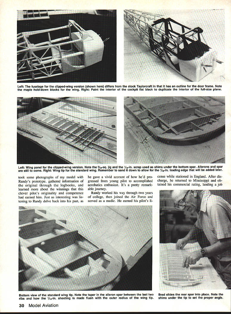
Glue the F‑3 and F‑4 pieces in place on the main frame. For the clipped‑wing version, frame the door with 3/8 x 1/4‑in. balsa then sheet the front and sides with 3/32‑in. balsa. For the standard model, omit the door outline and sheet the area per the plans. Glue the top, bottom, and side stringers to the framework. Dowels that simulate steel tubing in the cabin area can be glued in along with F‑3. The entire cabin area is painted flat black (talcum powder mixed with black dope).
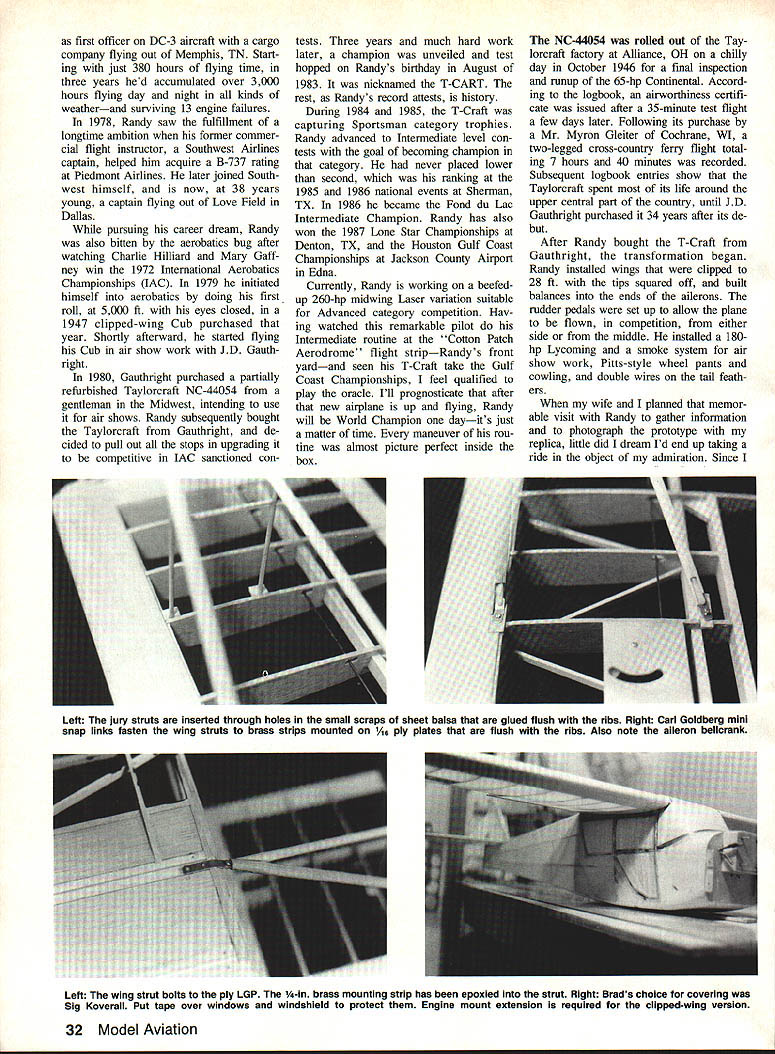
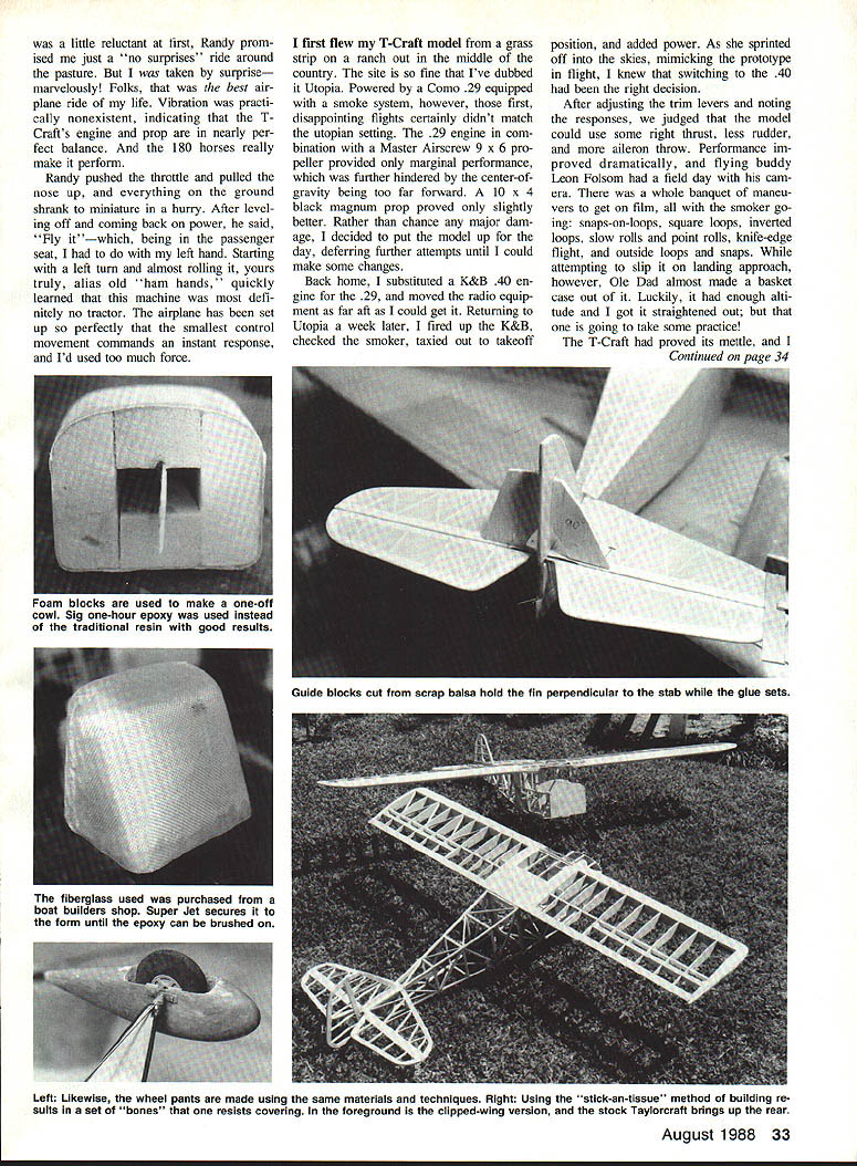
Bolt the wing onto the fuselage. Turn the assembly over and lay it on the bench. If installing the standard wing, shim the center section 1/8 in. to allow for dihedral when fitting the struts. Since the clipped wing has no dihedral, it is laid flat. Screw the strut mounting plate to the rear LGP as shown in photos. With 1/4‑in. brass fittings attached to the center‑of‑gravity mini‑links on the struts, mark holes for 3/8‑in. long No. 2 sheet metal screws. Use a 1/16‑in. drill to bore the holes and screw the struts on.
Make jury struts by sanding 1/8‑in. doweling to an oval shape and epoxying them to the main struts. Glue balsa scraps with holes for the jury struts onto the rail as shown. Install aileron‑crank mounting plates and 1/16‑in. music wire pushrods if not already done.
A Hayes .40 long engine mount with 6‑32 bolts through the firewall was used in both versions. Stiff wire is soldered in the head slots, and each bolt‑and‑wire assembly is secured with epoxy. Install the fuel tank and make throttle pushrod holes.
Wing
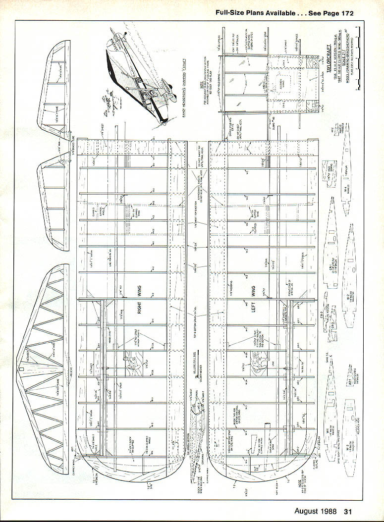
When building the wing panels, study the plans carefully to avoid misplacing ribs, especially when clipped‑wing plans are interposed over the standard wing drawing. Some ribs at the center section and tip are rearranged.
Place a 3/16‑sq. balsa strip over the plans at the jig line. Shim the bottom 1/4‑in. spar with scrap 1/16‑in. pieces, then pin the spar to the board. Pin all ribs in place, shimming the W‑1 pieces with 1/64 scrap. Place the 1/4 x 1‑in. trailing edge in the slots and pin the 1/4‑in. aileron section spar to the rear of the W‑3 ribs. Accurately position the 1/4‑in. top spar and slide the 1/4 x 1/2‑in. rear spar through the ribs. Go over all joints with Super Jet adhesive or equivalent.
For the standard wing, glue the 1/8‑in. tip pieces together, block up the tip 1/8‑in. end, and fit rib W‑4. For the clipped wing, glue a W‑2 rib in place and cut the tip to fit.
Glue the 1/4‑in. leading edge (LE) strip in place and sand it to a bevel matching the ribs. Install the 1/16‑in. sheet leading edge, leaving space at the center as shown on the plans. Turn the panels over and sheet the bottom LE. When dry, remove the panels and sand the 1/16 edges flush with the 1/8 x 1/2‑in. LE strip, then glue the 1/8‑in. LE cap in place.
When building the ailerons, sand a bevel into the 1/4‑in. spar and pin it to the plans. Mark the 1/2‑in. trailing edge for rib positions, ensure the tops of the ribs seat, and slip the ribs in place over the TE. Position the TE and glue the assembly with CyA.
Draw a 72‑in. straight guideline on the workbench to assist in assembling the wing panels and center section accurately. Using the rear edge of the bottom spars and the spar slots on the CR‑1 pieces of the center section as reference points, pin the center section down, line up the wing panels with the guideline, and pin them into place. The standard wing requires a 5/8‑in. block under the outer rib for dihedral; the clipped wing is flat. Use epoxy to join the panels to the center section. After the epoxy cures, remove the wing from the board and install the aileron bellcranks, torque rods, and pushrods per the plans.
Covering and finishing
I used Sig Koverall and nitrate dope on both versions, but any heat‑shrink covering is acceptable. Use sufficient coats of primer or dope to achieve a scale appearance.
Install the windshield and windows, covering them temporarily with masking tape to keep them clean. Mount the stabilizer, keeping it parallel with the wing. Install the elevator and glue on the fin using 90° triangles to keep it square with the stabilizer.
Make up the tailwheel assembly and glue it in place with epoxy. Hinge and install the rudder. Glue 1/4‑in. balsa fairings to the top of the stabilizer.
Bend the landing gear per the pattern on the plans and fill it in with 3/8‑in. balsa, sanded to fair into the wire. Cover the landing gear and finish with nitrate dope.
Transcribed from original scans by AI. Minor OCR errors may remain.

