
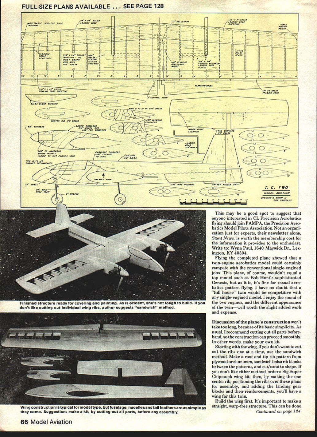
T.C. TWO
By Dick Sarpolus
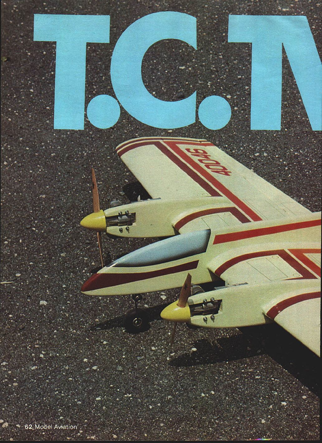
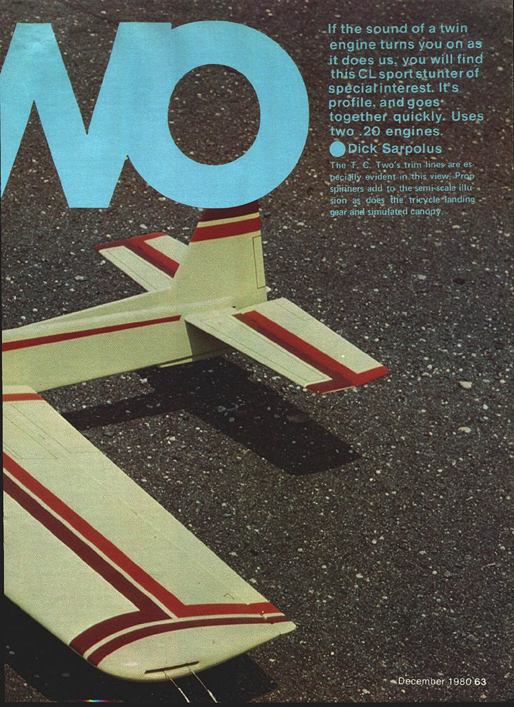
If the sound of a twin engine turns you on as it does us, you will find this CL sport stunter of special interest. It's a profile model and goes together quickly. It uses two .20 engines.
Profile models
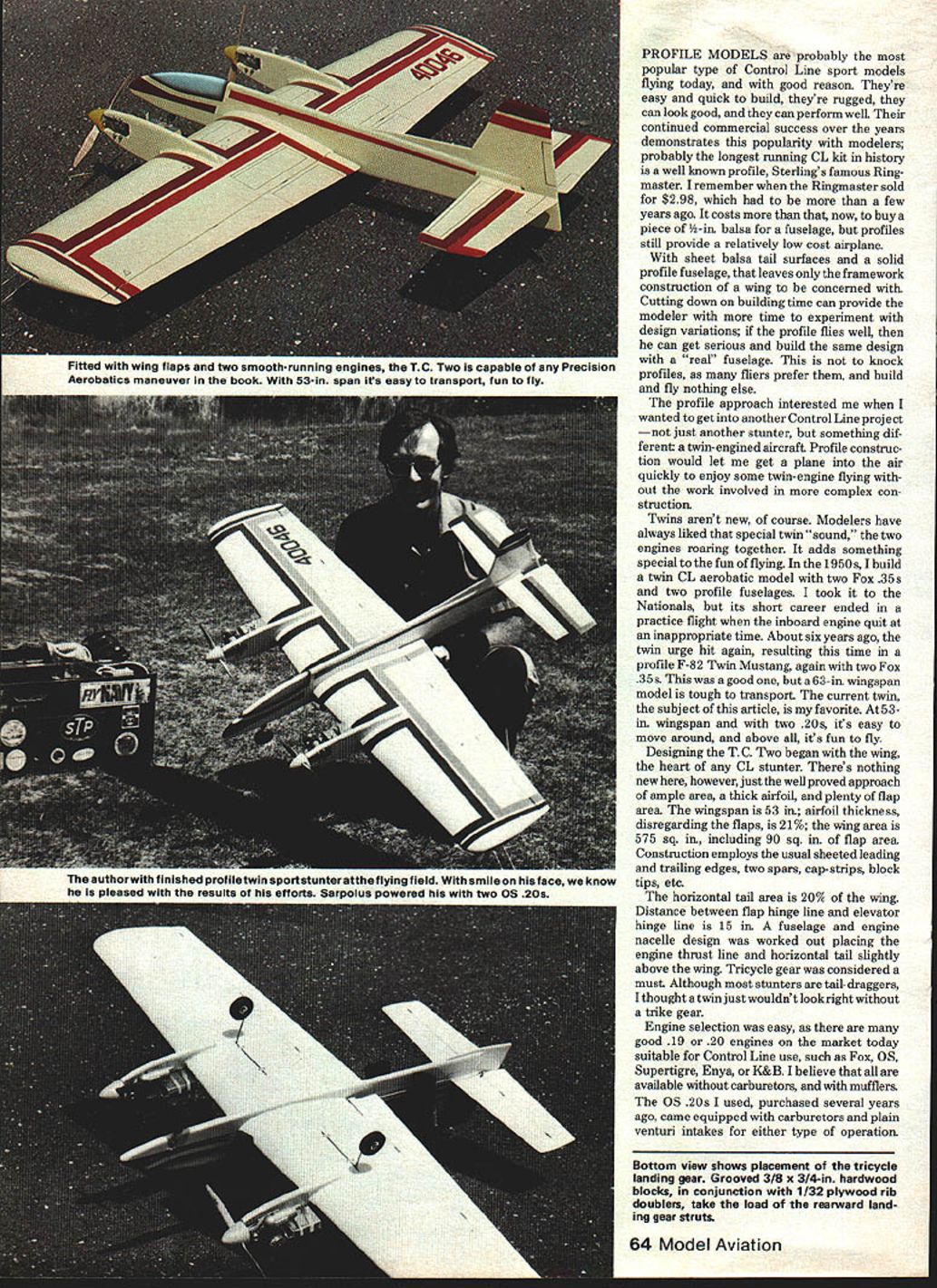
Profile models are probably the most popular type of Control Line (CL) sport models flying today, and with good reason. They're easy and quick to build, rugged, can look good, and can perform well. Their continued commercial success over the years demonstrates this popularity with modelers. Probably the longest running CL kit in history is a well-known profile: Sterling's famous Ringmaster. I remember when the Ringmaster sold for $2.98. It costs more than that now to buy a piece of 1/4-in. balsa for a fuselage, but profiles still provide a relatively low-cost airplane.
With sheet balsa tail surfaces and a solid profile fuselage, only the framework construction of a wing remains. Cutting down on building time can provide the modeler more time to experiment with design variations; if the profile flies well, he can build the same design with a conventional fuselage later. This is not to knock profiles — many fliers prefer them and build and fly nothing else.
Why a twin?
The profile approach interested me when I wanted another CL project—not just another stunter, but a twin-engined aircraft. Profile construction would let me get a plane into the air quickly to enjoy twin-engine flying without the extra work of more complex construction. Modelers have always liked the special twin "sound," the two engines roaring together. It adds something special to the fun of flying.
I've built twins before: in the 1950s a twin CL aerobatic model with two Fox .35s and two profile fuselages, and about six years ago a profile F-82 Twin Mustang with two Fox .35s (a good flyer but bulky at 63 in. wingspan). The current twin, the T.C. Two, is my favorite: 53 in. wingspan, two .20s, easy to move, and above all, fun to fly.
Design highlights
- Wingspan: 53 in.
- Airfoil thickness (excluding flaps): 21%
- Wing area: 575 sq. in. (includes 90 sq. in. of flap area)
- Horizontal tail area: 20% of the wing
- Distance between flap hinge line and elevator hinge line: 15 in.
- Construction: sheeted leading and trailing edges, two spars, cap-strips, block tips, etc.
- Landing gear: tricycle (trike) — chosen because a twin just wouldn't look right without it
- Engine thrust line and horizontal tail set slightly above the wing
Engines, mufflers, and fuel
Engine selection is easy: many good .19 or .20 engines are suitable for Control Line use, such as Fox, OS, Supertigre, Enya, or K&B. Many are available without carburetors and with mufflers. The .20s I used came equipped with carburetors and plain venturi intakes for either type of operation.
- Mufflers: Stock OS mufflers were used. Mufflers are recommended to maintain peace with flying-field neighbors.
- Fuel tanks: Fox 2½-ounce, 2-in. wide square wedge models, rubber-banded in place.
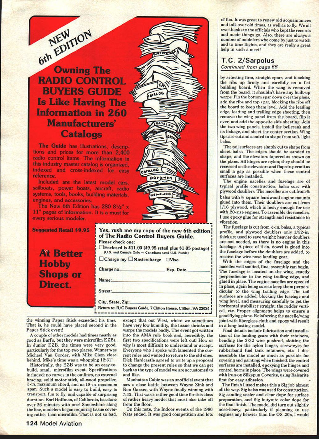
A note for those interested in CL Precision Acrobatics: consider joining PAMPA (Precision Aerobatics Model Pilots Association). Their newsletter, Stunt News, is useful. Write to: Wynn Paul, 1640 Maywick Dr., Lexington, KY 40504.
Flying
Flying the completed plane showed that a twin-engined aerobatics model can compete with conventional single-engined jobs for casual aerobatics pattern flying. It won't equal a top model such as Bob Hunt's sophisticated Genesis, but it is fine for sport flying. I enjoy the sound of the two engines and the different appearance of the twin—well worth the slight added work and expense.
Construction
Discussion of the plane's construction won't take long because of its basic simplicity. As usual, I recommend cutting out all parts beforehand so construction can proceed smoothly — in other words, make your own kit.
Wing
Designing the T.C. Two began with the wing — the heart of any CL stunter. Use the well-proven approach of ample area, a thick airfoil, and plenty of flap area. If you don't want to cut out ribs one at a time, use the sandwich method: make a root and tip rib pattern from plywood or aluminum, sandwich balsa rib blanks between the patterns, and cut/sand to shape.
If you prefer not to use either method, order a Sig Super Chipmunk wing kit; by making one center rib, positioning the ribs over these plans for assembly, and adding the landing gear blocks and reinforcements, you'll have a wing for this twin.
Build the wing first. Make a straight, warp-free structure by selecting firm, straight spars and blocking the ribs firmly and carefully on a flat building board. When the wing is removed from the board, it shouldn't have built-up warps.
Steps:
- Pin the bottom spar down over the plans, add the ribs and top spar, blocking the ribs off the board to keep them level.
- Add the leading edge and leading/trailing edge sheeting.
- Remove the wing panel from the board, flip it over, and add the opposite side sheeting.
- Join the two wing panels, install the bellcrank and its linkage, and sheet the center section.
- Cut and sand wing tips to shape from soft, light balsa.
Tail and controls
The tail surfaces are simply cut to shape from sheet balsa. Sand the edges to shape and taper the elevators as shown on the plans. All hinges are nylon and should be recessed on the elevators and flaps to permit as small a gap as possible when installed.
Engine nacelles and fuselage
The engine nacelles and fuselage use typical profile construction: balsa core with plywood doublers.
- Nacelles: Cut from 3/8-in. balsa with 3/8-in. square hardwood engine mounts glued into them. Doublers are 1/16-in. plywood, heavy enough for .20-size engines. Use epoxy for strength and vibration resistance.
- Fuselage: Cut from 1/2-in. balsa. Use plywood doublers only 1/32-in. thick to save weight (no engine in the fuselage). Glue a piece of 1/2-in. dowel into the fuselage before adding doublers to receive the wire nose landing gear.
With edges well sanded, final assembly can begin. Locate the fuselage on the wing exactly perpendicular to the wing trailing edge and glue in place. Epoxy the engine nacelles in place, keeping them perpendicular to the wing trailing edge. Add the tail surfaces, blocking the fuselage and wing level and measuring carefully to get the horizontal stabilizer straight and the rudder vertical. Proper alignment helps ensure a good-flying plane. Reinforcing the nacelle/wing joint with fiberglass cloth and epoxy will result in a long-lasting model.
Final details and finishing
Final tasks include fabricating and installing the landing gear with their retainers, bending the 3/32-in. wire pushrods, slitting surfaces for the nylon hinges, installing screw-eyes for rubber-band fuel tank retainers, etc. Disassemble the model as much as possible for covering and painting; when finished, install the control surfaces, epoxying the hinges and control horns in place.
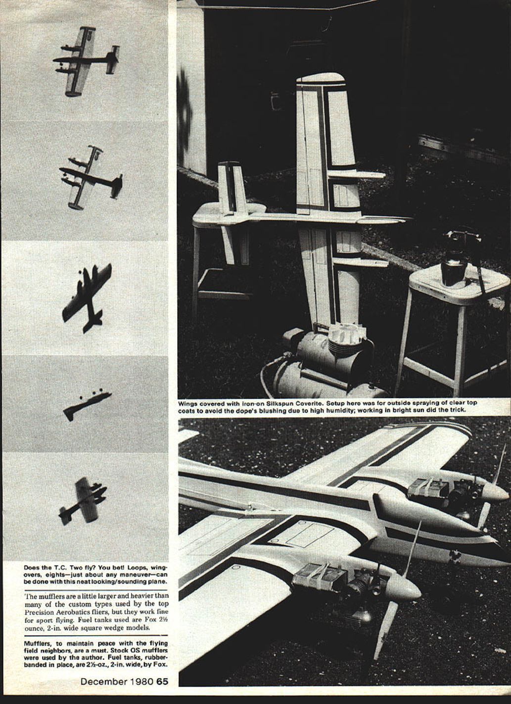
The wings were covered with iron-on Silkspan Coverite, using Balsarite first for easy adhesion. The finish I used is mostly Sig products: Sig balsawood for construction, Sig doping sealer and clear dope for surface preparation, and Sig butyrate color dope for the final finish.
The model did turn out slightly nose-heavy. If planning to use engines heavier than the OS .20s, consider shortening the engine nacelles by 1/2 in. or 3/4 in. to permit proper balance without adding tail weight.
Name
The name comes from a young friend, Trent Charles, affectionately known as T.C.; I thought he'd like an airplane named after him—so, the T.C. Two.
What we have here is a good-sized profile model, easy to build quickly, offering good aerobatic performance plus the thrill and excitement only a twin-engined model can give. Try it — you'll like it, too.
Transcribed from original scans by AI. Minor OCR errors may remain.

