
Techniques for RC Aircraft
- Objectives
- Criteria of Success
- The Test Specimen
- Test Setup
- Test Loads
- Test Procedure
- Instrumentation
- Data Requirements
Objectives
Objectives are always hard to define. You may start with something generic like "safety," but you must be specific: how much safety is required? A practical objective might be: "To perform a static loading test of the wing structure which will simulate the symmetrical wing bending caused by maximum positive high angle of attack at maximum velocity." That is a real flight condition you can analyze from the design and mission, develop acceptable test loads, and then test for.
Example: designing a Formula 1 Pylon Racer. Estimate maximum airspeed 150 mph and turning radius 100 ft. Use the following equations and definitions:
- Centrifugal force:
F = w v^2 / (g r) where w = weight (lb), v = velocity (ft/s), g = acceleration of gravity = 32.2 ft/s^2, r = turning radius (ft). Conversion: 1.467 = factor from mph to ft/s. v^2 means velocity squared.
- Dynamic pressure:
q = 0.001189 v^2 (the factor 0.001189 incorporates air density and unit conversions).
- Lift:
L = c_L q S where c_L = airfoil section lift coefficient (dimensionless), S = wing area (ft^2).
For v = 150 mph:
- Convert to ft/s: 150 × 1.467
- q = 0.001189 × (150 × 1.467)^2 ≈ 57.6 lb/ft^2
Example calculations:
- A 6-lb model at 150 mph turning on a 100-ft radius needs:
F = 6 × (150 × 1.467)^2 / (32.2 × 100) ≈ 90 lb of lift from the wing → a 15-G turn (90/6 = 15).
- Allowing ~15% more lift to account for down tail force gives about 103.5 lb total lift required.
- If wing area = 450 in^2 = 450/144 = 3.125 ft^2, lift per ft^2 = 103.5 / 3.125 = 33.1 lb/ft^2.
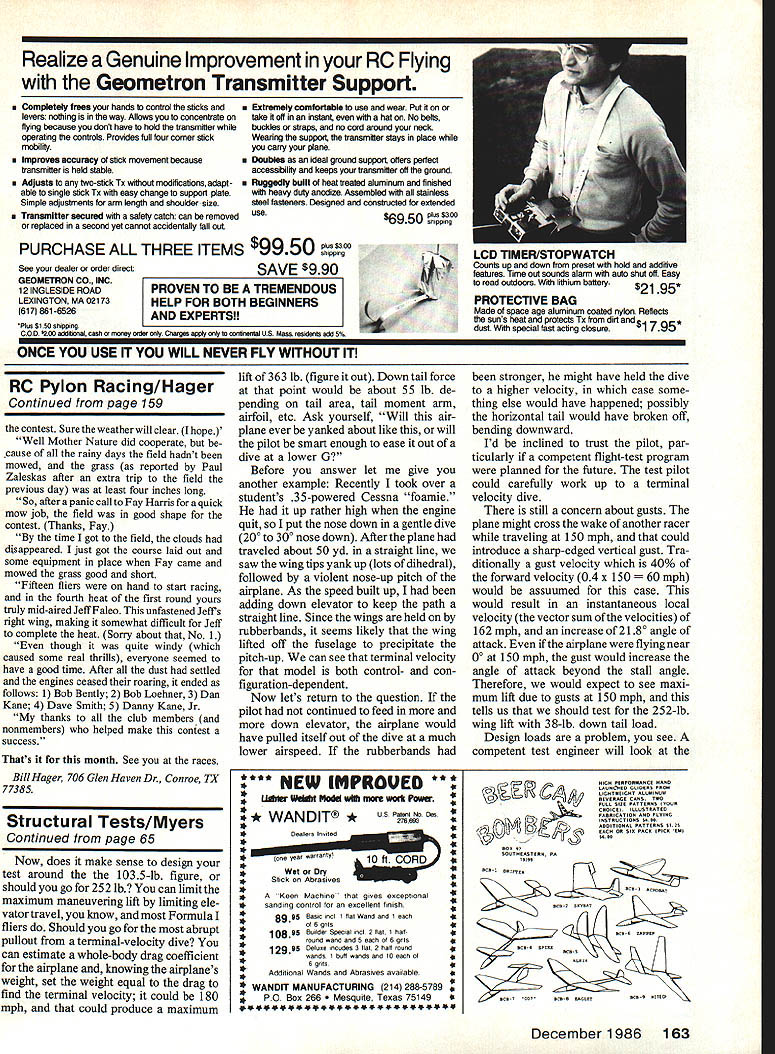
- Required lift coefficient: c_L = 103.5 / (57.6 × 3.125) ≈ 0.575. Airfoil data may show c_L could go as high as 1.4.
- Maximum lift estimate at 150 mph: (1.4 / 0.575) × 103.5 ≈ 252 lb total, or ≈ 80.6 lb/ft^2.
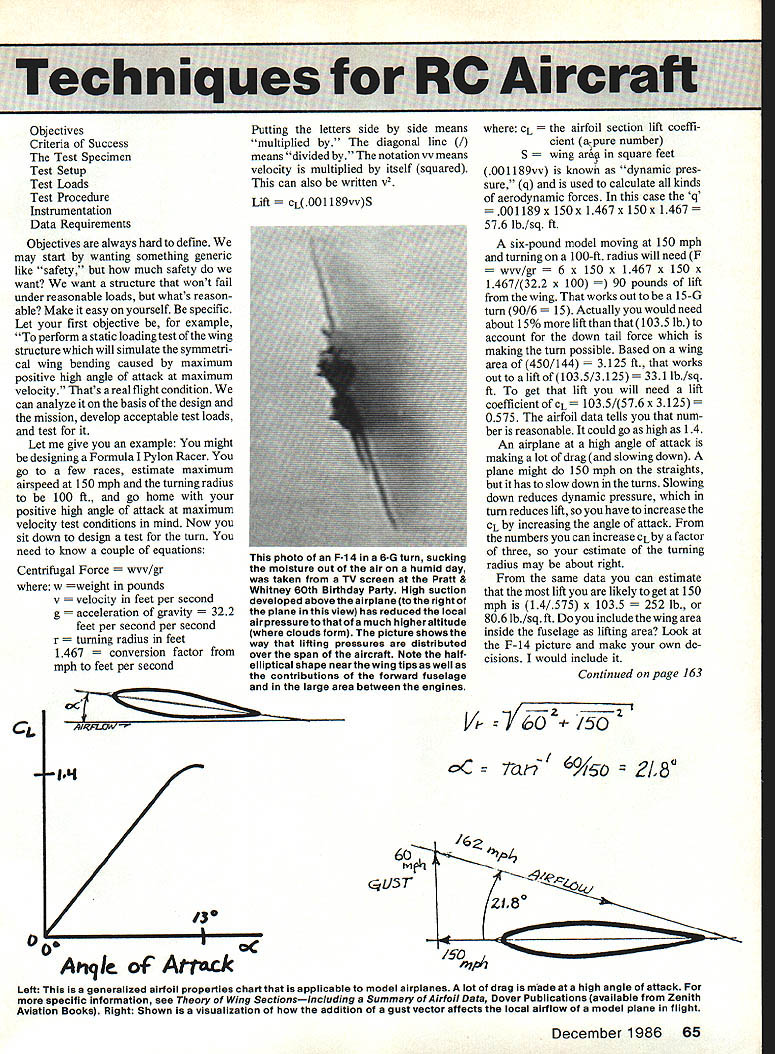
Include the wing area inside the fuselage as lifting area if it contributes—look at full-scale examples (e.g., F-14) and decide. I would include it.
Gusts: a sharp-edged vertical gust from another racer is a concern. Traditionally assume gust velocity = 0.4 × forward velocity (0.4 × 150 = 60 mph). The instantaneous local velocity is the vector sum ≈ 162 mph, producing an angle-of-attack increase of ≈ 21.8°. Even if flying near 0° at 150 mph, the gust could exceed stall angle and produce maximum lift in this condition. This suggests testing for the 252-lb wing lift with a 38-lb down tail load.
Design loads are a problem: competent test engineers consider the worst plausible combination of events in service and attempt to test for that—carefully.
Criteria of Success
Decide what constitutes success for the wing structure:
- Is cracking allowed so long as the structure does not separate into two or more pieces (concealed damage may exist)?
- Is crushing acceptable if the dihedral increases (easy to measure)?
- Have you designed a sacrificial yield feature that will reveal overload without catastrophic failure? (Example: Lee Renaud put a 1/8-in.-dia. steel dowel in the wing root of the Aquila to indicate overloads without breaking.)
- Total failure is easy to recognize; subtle success criteria must be defined and checked.
Test Specimen
- Specify the representative specimen: full wing, center section, or a scaled/test subassembly.
- Consider construction types (balsa-sheeted foam-core, Old-Timer style with skinny spars and ribs) when choosing support and load distribution.
Test Setup
- Keep the setup simple where appropriate: two sawhorses with padded supports can work for many pattern wings—use pillows or padded supports to avoid local crushing.
- For fragile-spar construction, spread the load more carefully—distribute lift loads across ribs and spars. Look to full-scale examples (e.g., F-14 load distribution) for ideas.
- Make jigs or fixtures that simulate support conditions encountered in flight.
Test Loads
- Recognize you cannot guarantee you designed for the single most critical condition the aircraft will ever encounter, but good design, testing, flying experience, and record-keeping reduce repeated mistakes.
- Learn from past failures: e.g., the Sun-Fli 4-20 had large maple blocks in each wing panel for landing gear; blocks were supported only by soft 1/8" balsa ribs and thin doublers and repeatedly tore out or allowed wheels to punch through the wing. The plans didn’t specify operating surface (turf vs. pavement), so tests or stronger installations are required when operating conditions differ.
- Crash loads:
- Primary structure should protect the radio and engine. Good RC designs use ample plywood around the radio compartment (see Bob Abele designs).
- The U.S. Navy criterion for pilot protection is 40-G forward and 20-G downward. For model work you can apply similar static tests to components:
- Chainsaw-engine extension mount: about (44.7 × 6 lb) ≈ 268 lb (as an example of a large load).
- Mounts for .40 to .60-size engines: resist about 50 lb.
- Radio tray (four servos, switch harness, receiver, battery): resist about 35 lb.
- Servo rails: resist about 5 lb per servo.
- Handling and transportation: include all causes of "hangar rash." Packing and shipping impose loads often overlooked—consider reinforcing mounting and contact areas.
Test Procedure
- Define stepwise load increments and inspection points.
- Monitor and record visible deformations, cracking, displacement (e.g., dihedral change), and any yielding at designed sacrificial points.
- Repeatability: perform multiple cycles where relevant to observe fatigue or progressive damage.
Instrumentation
- Use appropriate instruments to measure load, displacement, strain, and deflection as required by the test objectives.
- Simple setups may rely on calibrated weights and visual/metric measurements; more complex tests may use load cells, strain gauges, and data acquisition.
Data Requirements
- Record load vs. deflection curves, locations and types of damage, load at first crack or yielding, and final failure mode.
- Maintain test logs to inform future designs and improvements.
Practical Advice and Anecdotes
- Keep records of designs, flights, and failures—each iteration makes the next design easier and prevents needless overdesign.
- If uncertain about what a structure was designed to withstand (e.g., landing gear intended for pavement vs. turf), test it to the expected operating environment.
Author: George M. Myers, 70 Froehlich Farm Rd., Hicksville, NY 11801.
Engines (Inconsistent Runs and a Fix)
Over the last decade the author experienced inconsistent runs on ST.46 engines—needle valves incredibly sensitive, speeds varying flight to flight, and engines sometimes breaking into a two-cycle and staying there. After examining a problem engine, discoloration (blue hue from fuel) was noted on the piston below the ring, and corresponding polished areas were found on the cylinder wall. This indicated "blowby"—the seal between ring and cylinder wall is broken and explosive charge escapes, reducing cylinder pressure and torque.
Theory: the piston ring was effectively "hydroplaning" on a thin oil film over highly polished cylinder-wall areas, destroying the seal and producing erratic, needle-sensitive engine runs. The hydroplaning analogy: like a tire on a wet runway, a lubricating film prevents a good seal/contact unless there is surface texture to disperse the film.
Fix that proved successful:
- Buy an inexpensive brake-cylinder hone from an auto-parts store.
- Chuck the hone in a drill press and run at the slowest possible speed.
- Hone the cylinder walls until they are uniformly dull with a crosshatch pattern.
The tiny scratches produced by the hone act like grooves in a runway, allowing oil to dissipate and preventing the ring from hydroplaning—restoring a reliable seal and consistent four-cycle operation. This fix has proved successful for the author to date.
Transcribed from original scans by AI. Minor OCR errors may remain.

