
Ten Penny Speed Trainer
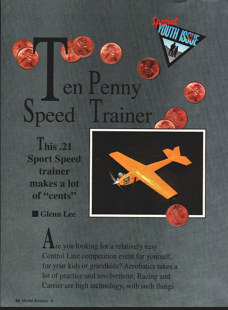
This .21 Sport Speed trainer makes a lot of "cents"
By Glenn Lee
Are you looking for a relatively easy Control Line competition event for yourself, your kids or grandkids? Aerobatics takes a lot of practice and involvement; Racing and Carrier are high-technology with such things as shut-offs and throttles; but Speed is simple: you just have to take off, get in the pylon, and fly level. All you need is a good engine and a stable airplane.
This .21 Sport Speed trainer is easy to build and easy to fly. There are several good engines available to power it, and some of them are quite inexpensive. Current AMA rules for Sport Speed allow profile models in competition, so you do not have to build a fancy speed model with magnesium pans, streamlining, monoline, tuned pipes, or other trick stuff.
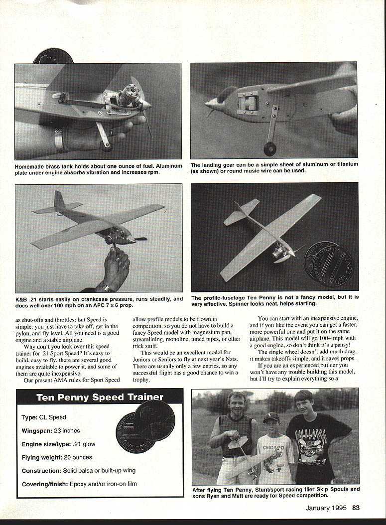
This model would be excellent for Juniors or Seniors at next year's Nats. There are usually only a few entries, so any successful flight has a good chance to win a trophy. You can start with an inexpensive engine and later install a faster one on the same airplane. With a good engine this model will exceed 100 mph.
Designed by Glenn Lee.
Specifications
- Type: CL Speed
- Wingspan: 23 inches
- Engine size/type: .21 glow
- Flying weight: ~20 ounces
- Construction: Solid balsa or built-up (hollow) wing
- Covering/finish: Epoxy and/or iron-on film
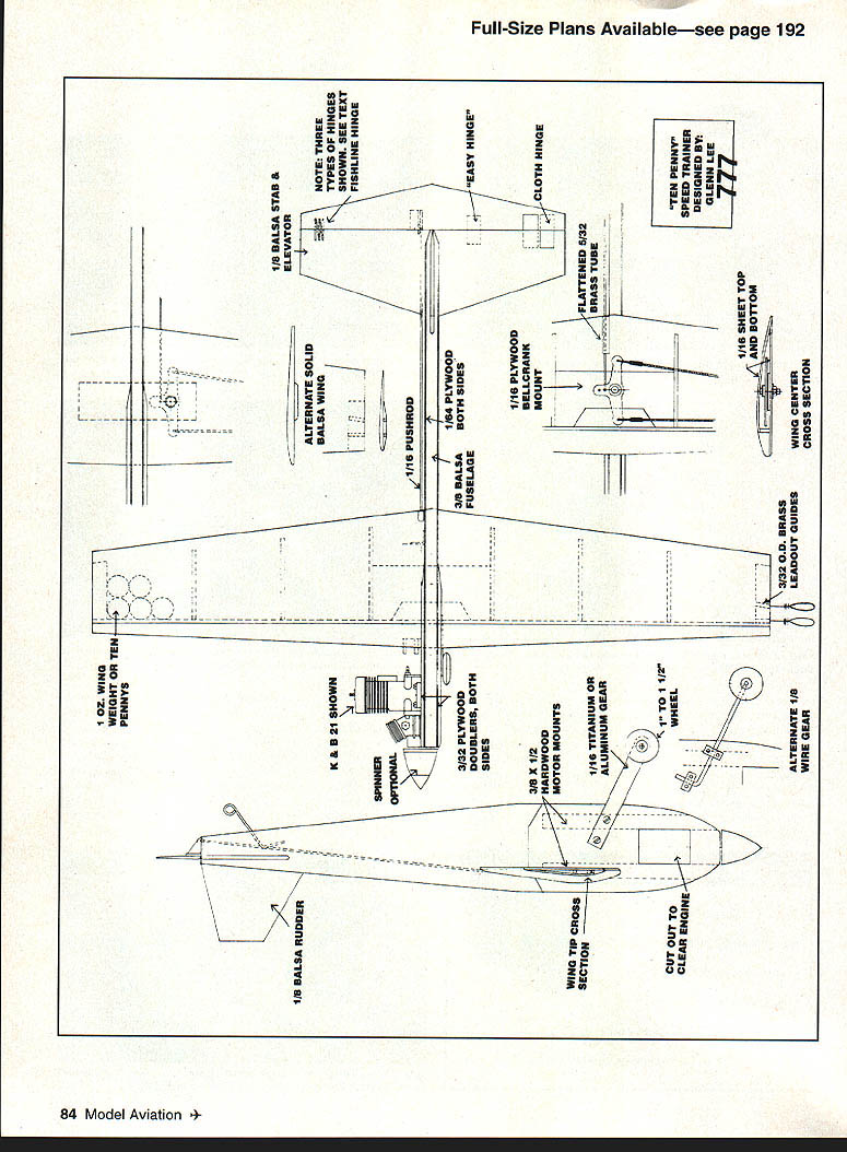
- Typical items shown on plans:
- 1/16" pushrod
- 1/8" balsa stab & elevator
- Several hinge types shown (fishline, Easy Hinge, cloth hinge)
- Flattened 5/32" brass tube for pushrod exit
- 1/16" plywood bellcrank mount
- 3/32" plywood on both sides of nose
- 3/8" balsa fuselage (profile)
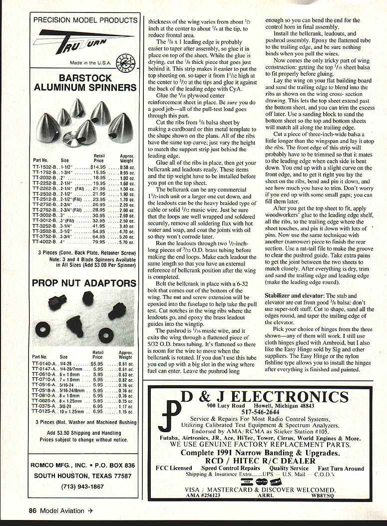
- Spinner optional
- K&B .21 shown on plans
- ~1/2 oz wingtip weight (about ten pennies)
- 1/16" sheet top and bottom wing sheeting
- 3/32" O.D. brass leadout guides
- Alternate 1/8" wire gear
- 1" to 1-1/2" wheel
- 1/8" balsa rudder
- 3/8" x 1/2" hardwood motor mounts
Construction
Look the plans over carefully before starting. Decide which part to build first; usually start the fuselage so while glue is drying you can work on other parts.
Fuselage
- Pick a good piece of firm balsa for the fuselage (example given: 7/8" x 3"). Do not use super-soft wood for primary structure.
- Prepare hardwood engine mounts (examples: 3/8" square or 3/8" x 1/2"); they should be the same thickness as the fuselage balsa where they are fitted.
- Saw slots for the mounts so the distance between them fits your engine. If you lack power saws, trim-fit with an X-Acto knife.
- The plans show full-length thin plywood sheeting on both sides of the fuselage extending under the nose doublers. Use 1/64" or 1/32" plywood for these sheets — they greatly increase strength and crash resistance.
- Cut the plywood at least 1/2" oversize around the edges so you can trim after gluing.
- Glue the two plywood sheets and engine mounts to the fuselage with epoxy or aliphatic resin woodworkers' glue. Clamp and weigh the assembly on a flat surface; use waxed paper between the fuselage and board to avoid accidental glue bonding.
- After glue is dry, trim the excess plywood and shape the fuselage.
- Add 3/32" plywood doublers to the front. Taper the back edges to blend into the fuselage. To hold pieces while gluing, locate them and temporarily drive a small nail or brad through the plywood a little into the fuselage; remove nails after glue dries.
- Round corners, test-mount the engine, and streamline the nose area.
Notes on engine mounts and reinforcement
- If available, saw a 1/16" aluminum plate to support the engine; it will absorb vibration and stiffen the front end, improving rpm.
- Install a little out-thrust for initial flights by placing washers under the front mounting lug holes; remove the washers after trimming flight technique.
Wing
Choice: hollow built-up wing or solid balsa wing. Either will work but have different pros/cons.
Solid balsa wing
- Use a medium-heavy 1/4" block and carve the airfoil with a block plane, carving knife and sanding block.
- A solid wing can be built thinner since the bellcrank does not have to fit inside. External controls add drag but are acceptable for ease of construction.
Hollow (built-up) wing (preferred for neatness and possible speed)
- Start with 1/16" hard balsa bottom sheet cut to shape; splice sheets with CyA if needed.
- Leading edge: glue a 3/8" x 1" leading edge on top of the sheet; easier to taper after assembly.
- Just behind the leading edge glue a 1/8" high strip tapered from about 1/32" at center to 3/32" at the tips to form the leading shelf for top sheeting.
- Glue a 1/16" plywood center reinforcement — this takes the pull-test load.
- Cut ribs from 1/8" balsa sheet using a template. All ribs have the same top curve; vary rib height to match the support strip behind the leading edge.
- Glue ribs in place.
- Install bellcrank and leadouts and wingtip weight before top sheeting.
- Bellcrank: any commercial ~1-1/2" unit or cut-down larger unit.
- Leadouts: heavy braided cable or solid 1/32" music wire; make end loops well wrapped and soldered, clean flux, coat joints with aliphatic resin glue to prevent corrosion.
- Run leadouts through two 1/2" long pieces of 3/32" O.D. brass tubing before making end loops.
- Make each leadout the same length so you have an external reference of bellcrank position.
- Bolt the bellcrank in place with a 6-32 bolt that comes out of the bottom of the wing; the nut and bolt extension will be epoxied into the fuselage to help take the pull load.
- Cut notches in ribs where leadouts pass and epoxy the brass leadout guides into the wingtip.
- Install a wingtip weight of about 1 ounce (approx. ten pennies) near the outer wingtip to keep the airplane from rolling in on takeoff. Epoxy the weight in place, smear glue over it, and cover with a piece of fiberglass cloth for security.
- Pushrod: use 1/16" music wire that exits the wing through a flattened 5/32" O.D. brass tube; flattening allows clearance for the wire and avoids a large slot that could let fuel in.
- Top sheeting: sand the trailing edge to match ribs so the top sheet will extend past the bottom sheet and trim later. Fit a 3" wide top sheet in two pieces if necessary; use woodworkers' glue on the leading edge shelf, ribs and trailing edge contact points and pin until dry. Make a groove to clear the pushrod guide. Take care to match the butt joint between the top sheets closely. After drying, trim and sand the leading and trailing edges and round the leading edge.
Strength considerations
- The model weighs about 20 ounces with a K&B .21; a pull test can reach ~60 pounds. The wing-to-fuselage joint and center reinforcement must be built to withstand this load.
- Reinforce the wing-fuselage joint with epoxy and a fillet: glue a 1/4" x 45° balsa strip under the wing or apply a filled epoxy fillet around the junction on both sides of the fuselage.
Stabilizer and elevator
- Cut stab and elevator from good 1/8" balsa (not super-soft). Sand edges round and taper the elevator trailing edge.
- Hinges: choose among cloth hinges glued with Ambroid, the Easy Hinge (nylon) or the fishline (nylon) hinge. The Easy Hinge/nylon types allow installation after painting.
- For fishline hinge: drill hinge holes, thread the line on a needle, sew the line through from top to bottom so the line crosses at the hinge gap. Align stab and elevator, then glue the line in place with CyA.
- Cut the rudder from the same balsa, round the leading edge, taper the trailing edge, and glue it straight to the fuselage. Do not introduce rudder offset.
Final assembly
- Mark wing and stab positions on the fuselage with pencil or pen. Ensure the stab is at 0° incidence to the bottom of the wing.
- Cut a 1/8" slot for the stab on this line.
- Make a cardboard template of the wing cross-section, slide it onto the wing and trim until it fits at center. Trace the cutout onto the fuselage at the proper distance from the nose and cut with a jigsaw.
- Trial-fit the inboard side of the wing into the slot and remove interfering wood with a half-round file. Repeat until the wing slides snugly.
- Make clearance for the bellcrank bolt if it extends below the wing.
- Center the wing, check longitudinal squareness by measuring from wingtip corners to the rear of the fuselage, and use a square under the wing against the fuselage.
- When aligned, use CyA in several close-fitting areas at the wing-fuselage joint and hold until set. For gaps, use epoxy and work it into the opening.
- Epoxy the cavity where the bellcrank nut and bolt are embedded to strengthen the load path.
- Apply fillets or 1/4" balsa strips under the wing for added strength.
- Slide the stab into its slot, square it to the fuselage, and glue as with the wing.
- Install the landing gear:
- Wire gear: bent 1/8" music wire clamped to the side of the fuselage and pinned with nylon retainers.
- Flat gear: 1/16" titanium or aluminum filed to a streamlined cross-section (less drag).
- Mount gear on the left (inboard) side of the fuselage to maximize wingtip-weight effect.
- Bolt in the engine and install the tank.
Tank and pressure tap
- A simple all-metal tank running on crankcase pressure works well; ~1 ounce of fuel is plenty. Keep the tank narrow to minimize CG shift as fuel level changes.
- Off-the-shelf small RC tanks will work. Clamp the tank to the fuselage with J-bolts and rubber bands or a bent strip of tin and self-tapping screws.
- Buy a pressure tap that replaces an upper backplate screw or drill/tap the backplate. Common sizes for RC muffler pressure fittings are 4-40 and 6-32.
Finish
- Sand the entire airplane, round corners, and fill dents with a suitable filler (Model Magic or equivalent). Leave the wing trailing edge square (less drag than rounded).
- Finish options:
- All-dope: lightweight, not very fuelproof, requires multiple coats.
- Finishing epoxy resin: fuelproof but heavier and more difficult to sand.
- Recommended: epoxy finish (K&B or Hobbypoxy). Apply two coats of primer-surfacer, sand between coats, then a coat of colored epoxy. Sand most of the primer off before painting to keep weight down.
- Alternative: paint the fuselage and cover the wing with iron-on plastic covering, sealing edges with CyA.
- Use a sprayer if possible for a smoother finish. Ensure good fuel- and oil-resistant coating around the engine and tank area.
After finish is dry
- Install the control horn on the elevator, glue in the tail skid, and bolt on the landing gear.
- A spinner is optional but neat and helpful with a starter; a rounded prop nut also suffices.
Flying and setup
- Run the engine on the bench a few times before flying to learn starting and needle-valve settings. Most .21 ABC engines need little or no break-in.
- Start with a 7x5 or 7x6 APC or wood prop and good commercial 10% nitro fuel (e.g., Sig).
- Fastest prop for your particular engine and build may be ~6-1/2 x 5; experiment.
- Bolt the engine in with slight out-thrust (washers under the front mount holes) for the first flights; remove washers later as you learn to handle the model on takeoff.
- After proficiency, you can remove the landing gear and hand-launch the airplane (or use a skid), as was common before takeoff dollies.
Supplies and suppliers
Very few hobby shops carry Control Line equipment; sources for lines, handles, clips, etc.:
- Sig Mfg. Co. — general products, engines
401-7 S. Front St., Montezuma, IA 50171 Tel.: (515) 623-5154
- Morris — lines, neat bellcranks, clips
9044 Rushmore Blvd. South, Indianapolis, IN 46234 Tel.: (317) 271-1231
- Bear Necessities — variety of Control Line products
Box 549, Beecher, IL 60401-0549
If you have problems or need help, write to: Glenn Lee 819 Mandrake Dr. Batavia, IL 60510
Transcribed from original scans by AI. Minor OCR errors may remain.

