
Terrible Coupe
With a four-year string of victories, this model has proven itself to be one of the best-ever designs in Coupe d'Hiver modeling. — Chuck Markos
Introduction / Name
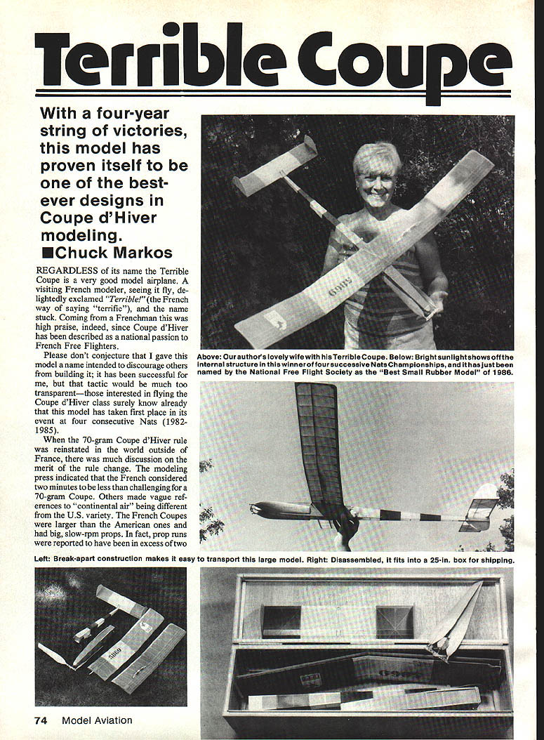
Regardless of its name, the Terrible Coupe is a very good model. A visiting French modeler, seeing it fly, exclaimed "Terrible!" (the French way of saying "terrific"), and the name stuck. Coming from a Frenchman this was high praise indeed, since Coupe d'Hiver has been described as a national passion of French free flyers.
Please don't conjecture that I gave the model that name to discourage others from building it; that would be too transparent. Those interested in flying the Coupe d'Hiver class surely know that this model took first place in its event at four consecutive Nats (1982–1985).
History and competition record
When the 70-gram Coupe d'Hiver rule was reinstated outside France there was much discussion about the merit of the rule change. The modeling press indicated the French considered two minutes less challenging for a 70-gram Coupe. Others made vague references to "continental air" being different from U.S. air. French Coupes were larger than American ones and used big, slow-rpm props; reported prop runs were sometimes in excess of two minutes.
I reasoned that a big Coupe built in the 1979 French style and kept to 70 grams would have no trouble with a 120-second max in still air. I incorporated a break-apart wing and fuselage for easier shipping so the model could be tested against European competition.
- My first try weighed 85 grams as built and required six grams of nose ballast to meet the English 70-gram event. That model later weighed 95 grams before being lost at Westover AFB in 1983; it had been twice the U.S. Coupe d'Hiver champion.
- The second model weighed 72 grams ready-to-fly and took first-place honors at the Reno Nats in 1984, but was later lost when the stab de-thermalizer (DT) failed during a local contest.
- The present model weighs 75 grams and incorporates a pop-off wing DT and a traditional stab DT.
Since 1980, these three models have executed 26 consecutive 120-second maxes in Nats competitions (most in still air before 10 a.m.). They have also proven to be good wind-thermal fliers, taking two wins at windy Westover Nats.
Construction notes
The following notes address questions modelers often ask at contests and comment on features and techniques not always standard to this type of modeling.
Propeller hub
- Hub material: tempered aluminum, worked with a drill press, Dremel tool, files and a hacksaw (fine-toothed blade recommended).
- Fit brass tubing liners into the hinge/shaft holes using a vise; make the tubing slightly overlong and use the pressure of the vise to create a slight distortion to keep the liner in place.
- Bend 3/32" music-wire hinges to accept 3/32" brass tubing. Slightly flatten the wire with a Dremel for a better fit and easier soldering.
- Wrap the joint with copper wire, add flux, and solder with Sta-Brite silver solder. Maintain 180° alignment while soldering; place lengths of 1/16" OD aluminum tubing into the brass sockets for alignment.
- Fine adjustment: file away excess copper-wire solder, add .015" brass shims as needed, then re-solder and file to final shape. Best hubs have shaft and hinge holes exactly perpendicular and parallel—any bias will fold prop blades and prevent a snug fit against the fuselage.
- Similar hubs may be purchased from FAI Model Supply or Jim Crockett Replicas.
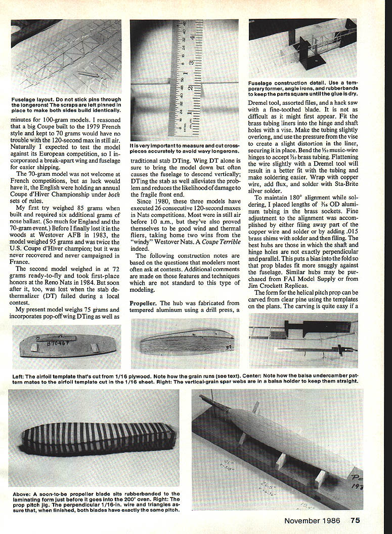
- A helical-pitch prop can be carved from clear pine using the templates on the plans.
Propeller blades (laminate)
- Blade sandwich: 1/32" hard sheet balsa + 0.6-oz glass cloth and epoxy + 1/16" sheet balsa.
- Soak balsa blanks in water, lash tightly to the pitch form with rubber bands, and bake at 200°F for 30 minutes.
- After cooling, coat the inside surface with a thin layer of slow-drying epoxy (Hobbypoxy Formula 1 recommended), add the glass cloth, re-lash to the form, and return to the 200°F oven for 30 minutes. Protect the form with Saran Wrap or similar plastic, and ensure oven temperature does not exceed 200°F.
- Finish with sandpaper and glue blades into a 3/16" birch-dowel shaft with 5-minute epoxy. Use a jig to set pitch. When correct, glue the prop shaft into the brass socket with cyanoacrylate (CyA).
- Drill a 1/16" hole through the socket and shaft and insert the hooks for the rubberband that folds the prop.
Fuselage layout and construction
- Layout: stick pins through the longerons into scraps left pinned in place so both sides build identically.
- Construction: use a temporary former, angle irons and rubber bands to keep parts square until glue is dry. Measure and cut crosspieces accurately to avoid wavy longerons.
- Final sanding: use 220- and 320-grit paper with a sanding block.
Wing construction
- Use a plywood rib template guiding a single-edged razor blade along the airfoil to produce uniform ribs. Orient the exposed grain of the plywood perpendicular to the chord axis to protect the template.
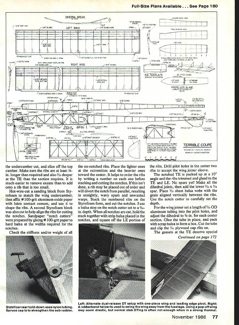
- Cut undercamber and slice off top camber. Make ribs at least 1/8" longer than required and 1/32" deeper at the trailing edge—it's easier to remove excess than add.
- Hot-wire cut a Styrofoam sanding block to match wing undercamber; affix #100-grit aluminum oxide paper with latex contact cement and use it to shape ribs.
- Prepare a second Styrofoam block to help align ribs for cutting notches. Make sandpaper "notch cutters" by gluing #100-grit paper to hard balsa at the required widths.
- Check stiffness/weight of all un-notched ribs. Place lighter ribs at the extremities and heavier ones toward the center. Number ribs before stacking and cutting notches to avoid misplacement.
- Stack numbered ribs on the Styrofoam form and cut notches. Use a balsa stop on the notch cutter set to a 3/16" depth. After cutting, hold the stack with strip balsa in the notches and square off the leading-edge portion. Drill pilot holes in the center two ribs to accept the wing joiner sleeve.
- The notched trailing edge is packed up at a 10° angle; trim and glue ribs to TE and LE. Make dihedral joints first, then add the 1/4 x 1/16" spar.
- Place 1/32" sheet balsa webs with grain aligned vertically between ribs; use the notch cutter to set depth carefully.
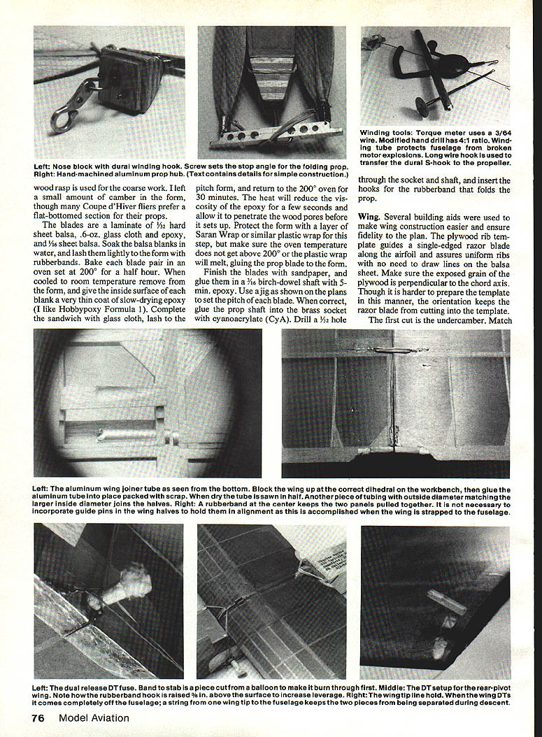
- Wing joiner: insert 7/64" OD aluminum tubing into pilot holes and adjust dihedral to 1/4" for each center section. Glue tube in place and pack with scrap balsa to form a box. Cut the tube and slip 1/8" plywood cap ribs on.
- Pay special attention to TE gussets: hand-fit each to match the TE and mind the wood grain.
- Use the undercamber sanding block clamped in a vise to scrub the wing with short strokes to remove construction unevenness.
Gussets and final woodworking
- Each TE gusset needs hand fitting for a perfect match to the trailing edge.
- Final sanding of the fuselage and wing should be done carefully with 220- and 320-grit paper and a sanding block.
Covering and finishing
- Give the framework two coats of dope wherever it will contact the covering. Use nitrate dope if available; otherwise use Sig Lite Coat butyrate.
- Japanese tissue is available from Peck-Polymers or Old-Timers Model Supply in various colors. Tissue has a grain direction—lay the bottom camber covering with the grain spanwise.
- Brush thinner through the tissue (first at the spar, then at the ribs) and rub lightly with a finger to press tissue into close contact while the dope is still soft.
- Cover the perimeter framework next. Trim excess tissue flush to the TE with a sharp razor blade but leave ~1/8" at the leading edge to curl to the top.
- Seal edges with dope using a fine brush. To prevent covering from pulling away from the undercamber after shrinking and doping, give the rib/tissue junctures a coat of dope before covering the top camber.
- Fuselage covering: two layers of tissue cross-grained at a 45° angle to the axis of the motor box (front portion). Do not apply tissue with biased grain to the tail boom—severe warping will occur.
- The covering was water-sprayed and shrunk, then given two coats of thinned dope. Spray doping is recommended for super-light models. Only three grams of weight were added in finishing this model.
Flying
- Preflight checks:
- Wing: slight wash-in of the inner right panel; both outer panels should be washed out.
- CG: with a 10-gram motor in place the CG should be as indicated on the plans.
- Trims: align dead straight ahead (one check method is to establish perpendicular reference lines on a tiled floor).
- Down and right thrust should be built in according to the plans.
- Test-glide to obtain a smooth right-hand turn using, in order: stabilizer tilt (up to 3/8"), sub-rudder adjustment, and stabilizer incidence.
- Always wind with the winding tube in place to protect the fuselage from exploding motors.
- Recommendation: Do not make more than three flights from a motor used in contest flying.
- Motor experience:
- I have flown the model with eight strands of 1981 4mm Pirelli, six strands of 1979 6mm Pirelli, and 10 strands of 1981 1/8" FAI supply rubber.
- At 70–75 grams you can exceed two-minute dead-air times with any of these motors.
- Best combination: eight strands of 4mm Pirelli wound to a torque of 1,500 gram-centimeters and up to 520 turns.
Notes on trim behavior:
- A big, slow-moving model like this is less susceptible to trim changes than smaller, faster models. It is forgiving and easy to adjust.
- Stalling climbs should be corrected with added downthrust or more right thrust before adding more turns.
De-thermalizer (DT) arrangements
- The present model incorporates a pop-off wing DT plus a traditional stab DT. Wing DT alone will usually bring the model down but often causes the fuselage to descend vertically; DTing the stab alleviates this and reduces the likelihood of damage to the fragile front end.
- The DT hooks and rubberband arrangement have been refined for a more positive action with less complication. Four methods were investigated; two most successful methods are described below.
- LE pivot (preferred): pivots on the wing leading edge and requires a LE mount similar to a stab DT. Used on a one-piece wing.
- TE pivot: requires rounding and reinforcing the trailing edge and using a hook to hold the rubberband at least 3/8" above the wing for enough leverage to pivot the wing from the fuselage.
- Dual sets of hooks help hold a two-piece wing together while in flight.
Questions / Contact
Questions or comments? Send a S.A.S.E. to: Chuck Markos 655 Carlisle Ave. Deerfield, IL 60015
Transcribed from original scans by AI. Minor OCR errors may remain.

