
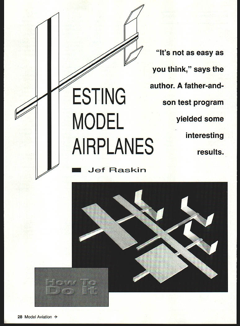
Testing Model Airplanes
By Jef Raskin
"It's not as easy as you think," says the author. A father-and-son test program yielded some interesting results.
The idea
I was explaining the term aspect ratio to my then-nine-year-old son Aza. For a rectangular wing, aspect ratio is span divided by chord. A wing of one-foot span and one-foot chord would have aspect ratio 1:1; a wing of four-foot span and one-foot chord would be 4:1. We talked about how larger wings can carry more weight or, for the same weight, fly more slowly than smaller wings. Aza noted that very small wings mean high speed to stay up (the F‑104 with tiny wings goes very fast).
Aza asked, "What difference does aspect ratio make in the way an airplane flies?" I explained that for full-size airplanes higher aspect ratios usually make them more efficient (better range, less fuel) and gave gliders as an example. He then asked whether the same would be true for models. Rather than try to explain Reynolds-number effects in detail, Aza suggested a simple experiment: build two (or more) models with different aspect ratios but keep everything else the same, and see which flies better.
Building the models
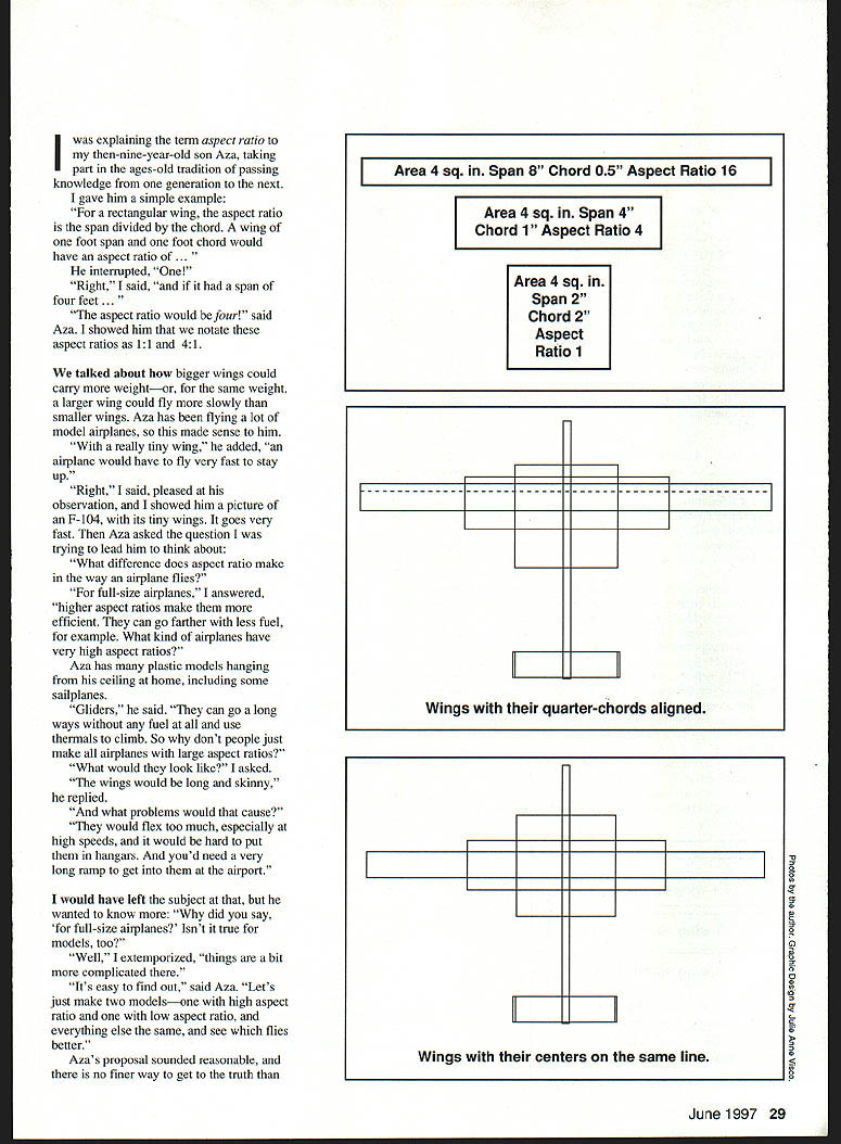
We decided on small balsa gliders with a wing area of four square inches. The three wings chosen were:
- Aspect ratio 1:1 — 2 in. × 2 in. (square wing)
- Aspect ratio 4:1 — span 4 in., chord 1 in.
- Aspect ratio 16:1 — span 8 in., chord 1/2 in.
Materials and basic geometry:
- Sheet of 1/32" balsa for the wings (so the same thickness for all wings).
- 1/8" × 1/8" sticks for tail surfaces and fuselage.
- Cyanoacrylate (CyA) glue to assemble the models.
- Stabilizer area set to 25% of wing area (our family's rule)—one square inch.
- Fuselage: simple 1 in. × 2 in. rectangle stick.
- Twin‑fin design to stiffen and align the stabilizer; fins about 1/2 in. chord and 3/4 in. high.
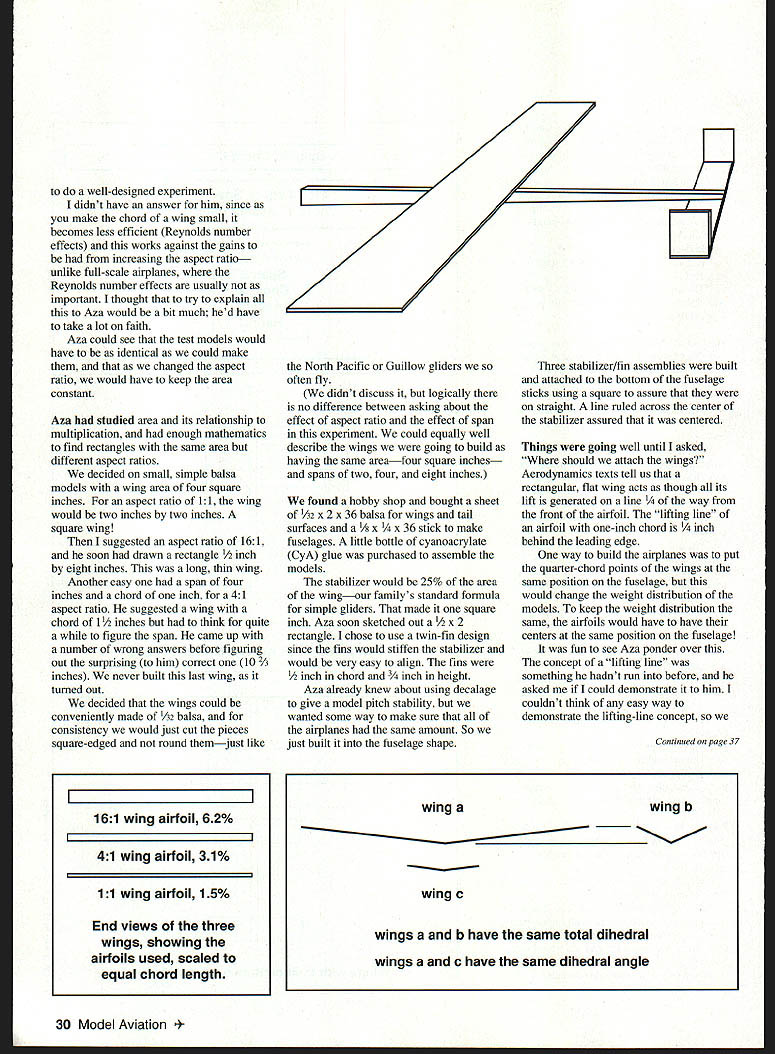
Because the wings were all the same absolute thickness (the 1/32" sheet) but had different chords, their thickness ratios differed:
- 16:1 wing — thickness ratio ≈ 6.2%
- 4:1 wing — thickness ratio ≈ 3.1%
- 1:1 wing — thickness ratio ≈ 1.5%
This meant the three models effectively had three different airfoils, a significant experimental impurity.
Experimental choices and compromises
Aza and I tried to make the models identical except for span and chord, but many practical choices influence the result:
- Wing placement on the fuselage: aerodynamic texts say a flat rectangular wing acts as if its lift is generated at the quarter‑chord line. One option was to align the quarter‑chord points of all wings at the same fuselage position; the other was to put the wing centers at the same position. We settled on aligning wing centers, acknowledging that neither choice is "pure" and that airplanes are sensitive to wing position.
- Dihedral: the 16:1 model was a bit unstable. We considered adding dihedral and whether to give all wings the same dihedral angle or the same vertical rise of the wingtips. We decided to keep the same dihedral angle (physically reasonable if lift is proportional to area). After trimming, the 16:1 flew stably without adding dihedral.
- Airfoil/thickness: using the same sheet thickness produced different thickness ratios (see above). To have the same airfoil shape proportionally, the wings would have needed different absolute thicknesses (different sheet thicknesses), but that raises the question of what "same" means — same absolute thickness or same thickness ratio? Another approach would be to scale models so chord is the same (same Reynolds number) but that complicates stabilizer sizing and trim.
- Fuselage coverage: the portion of wing covered by the fuselage differed. The 1:1 wing had much more wing area obscured by the fuselage than the 16:1 wing. Again, another impurity.
Trimming and balancing
- After assembly we weighed the models on a simple balsa balance and added clay at the top of the wing center until weights were equal. (We might have been better to place clay at the center of gravity, but that point was unknown at the time.)
- Nose weight was added so the models would fly. Two approaches were possible:
- Fly them, trim by trial and error until they flew well, then rebalance for equal weight.
- Balance all at a fixed fraction of the wing chord (e.g., 30% chord).
- We tried balancing at fixed points; 30% chord left them nose‑heavy and 50% was also wrong. We trimmed each by trial and error, then reballasted to equal weight. That still left the question: had we trimmed each optimally? Probably not.
Testing method
We chose distance as the performance metric because it relates to glide angle (lift-to-drag) when all flights start from the same height. Practical testing details:
- Launch height: Aza launched from a rise about five feet high. Soft grass cushioned landings. Most mornings were windless.
- Launch speed and technique: launches were by hand. Harder throws usually go farther, but an overly aggressive launch can loop a model. Getting identical launches is difficult.
- Repetition: we flew each airplane many times to get a feel for consistency and reduce variability.
- Unconscious bias: a major concern. Experimenters can unintentionally influence results (trimming more carefully, launching a favored model more vigorously, measuring distance differently, etc.). Blind or double‑blind methods are necessary to eliminate this, but difficult to arrange for hand‑launched model tests. I demonstrated unconscious bias to others with a radio slope soarer by flipping a switch that did nothing; everyone reported improved handling.
Results
- The 1:1 wing seemed best overall — most consistent in achieving distance.
- The 4:1 wing was a close second.
- The 16:1 wing sometimes produced the single longest flight, but on average it was usually the worst performer and was less consistent.
Aza concluded, correctly, that our test was not rigorous enough to isolate the effect of aspect ratio. Any consistent performance difference might well have been due to other variables (airfoil thickness ratio, wing/fuselage interference, slight warps, trimming differences), not aspect ratio alone. To draw firmer conclusions we would have needed multiple copies of each design and better control of variables — and ideally blind testing and a mechanical launcher.
Lessons and advice
- Many design changes cannot be tested in isolation; small, practical differences often confound experiments.
- Reynolds‑number effects and airfoil thickness matter for model airplanes and can negate expected gains from higher aspect ratios that apply to full-scale aircraft.
- Unconscious bias is powerful; blind testing is important whenever possible.
- When you read claims about model airplane design, ask how the test was done: Was the effect isolated? Were other variables controlled? Could unconscious bias be present?
A good experiment can be very hard to do. Aza learned that controlled testing is difficult and that results are often not clear cut — but that is part of the value of doing experiments.
Jef Raskin 8 Gypsy Hill Rd. Pacifica, CA 94044
Transcribed from original scans by AI. Minor OCR errors may remain.

