
Texas Wildcat
You could hear it coming from 10 miles out. The Texas Wildcat—its slipstream howling through brass tubes in the fuselage-mounted box radiators—gave a terrifying screech as it roared by in a wide-open pylon turn at nearly 200 mph. It's easy to see why the racer was nicknamed "Whistling Bill."
The Texas Wildcat and its sister ship, the Cactus Kitten, were sponsored by flamboyant Texas oilman and aviation enthusiast C. E. J. Cox and his strong-willed wife, Nellie. Nellie Cox, already famous as the first woman in America to have her own personal plane and pilot, ordered the Curtiss Aeroplane Company to build her a Gordon Bennett racer on April 13, 1920. Two months later, Mr. Cox ordered a second racer.
In an era when most airplanes looked like flying bird cages, the Wildcat and Kitten were notable as 90-day wonders. With only three months to complete the racers before they had to be shipped to France, the design emphasis was on maximizing speed and details were to be kept secret. The engine was the new Curtiss 430-hp C-12. The fuselage was planked with stressed-skin veneer and the wings were covered with doped fabric. The Wildcat was built with two sets of wings—a 32-ft high-lift wing for test flying and a thin 25-ft racing wing with a double-cambered airfoil. Finally, a rigid landing gear was used—a decision with fateful consequences for Cox's dream.
Test pilot Roland Rohlfs first flew the Wildcat shortly after she was christened Nellie. The racer exhibited severe aileron flutter that nearly ended Rohlfs' career; the problem was quickly corrected and he completed the test flights. Nellie persuaded her husband to assign her chosen pilot to fly in the Gordon Bennett race, bypassing Rohlfs. Furious at the snub, Rohlfs convinced Cox to reassign the other pilot to the Kitten, then painted "Texas Wildcat" in block letters on both sides of the plane.
Once in France, organizational problems and design flaws from the rushed execution became distressingly obvious. Incredibly, the monoplane (racing) wings had been left in America, so the Wildcat arrived assembled in its untested biplane form. On his first flight Rohlfs opened the throttle and the plane wouldn't accelerate—the extremely high-pitched racing prop simply didn't have enough bite, and the Wildcat had to be pushed to start its takeoff run. It covered the whole airstrip and part of a farmer's field before becoming airborne, then pitched violently in flight; Rohlfs barely managed to return and land, calling the flight a nightmare.
In desperation the designers worked nights laying out new ribs and spars. The French Morane-Saulnier factory provided workspace and a new set of biplane wings was completed and fitted in just four days. Time was running out. The racer rolled out smelling of fresh dope and with enough fuel for a 30-mile flight. Rohlfs took off at dusk; just after lift-off the wheels struck a hidden rut and the plane bounced into the air. The shock had broken wheel spokes in the rigid landing gear. On final approach the engine quit; during the dead-stick landing the broken spokes collapsed, the rigid gear dug into the ground, the airplane flipped, and the fuselage broke in half. Fortunately there was no fire and Rohlfs' worst injury was a dislocated shoulder.
The Cactus Kitten was never uncrated in France. It was shipped back to America and converted to a triplane.
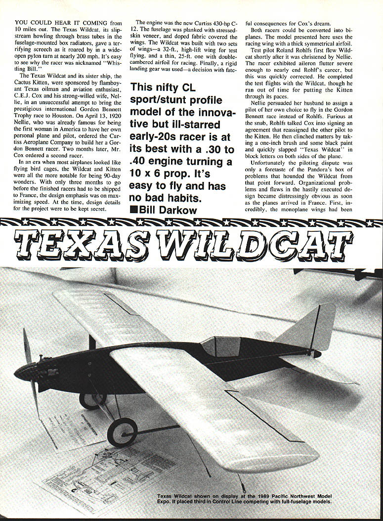
Note: This article also describes a CL sport/stunt profile model of the Wildcat. The model is best with a .30 to .40 engine turning a 10 x 6 prop, is easy to fly and has no bad habits.
Construction
The Wildcat model has three distinctive features that improve flight safety and make finishing easier: the exterior-mounted control system, the landing gear tied directly into the engine mounts, and unique plug-in wing struts. The exterior-mounted controls and landing gear are tied directly into 1/2 x 2-1/8 x 12-in. engine mounts. The plug-in wing struts are added after the model is finished.
Wing
- Make a rib pattern from thin metal or plywood.
- Cut ribs from three sheets of 1/16 x 15 x 36-in. balsa stock; use the remainder for the rudder.
- Join the wing spars with four 1/8 x 1/8 x 6-in. plywood doublers.
- Cut half-depth notches on 2-in. centers in the main spar for the wing ribs.
- Cut 24-in. leading and trailing edge planking strips from two sheets of 1/16 x 3 x 36-in. balsa. Use the remainder for cap strips and center section planking.
- Mark 2-in. spaces on the rear spar and the inside of the trailing edge planking.
- Assemble the ribs on the spars without gluing. Note double ribs at the center section and triple-laminated ribs at the strut attachment points.
- Pin the entire lower half of the trailing edge to a flat surface, being careful to keep it straight.
- Glue the rear of the wing ribs to the lower half of the trailing edge, leaving 1/2 in. of clearance at the back.
- Glue the upper half of the trailing edge to the rear of the lower half and the wing ribs.
- Remove the wing from the building board. Mark the wing rib locations at 2-in. intervals on the 1/4-in. leading edge, then glue the ribs in place. Rubber bands may be used to hold everything together.
- After checking alignment carefully, glue the ribs to the spars. Add the leading edge planking to complete the D-tube spar—the wing will become quite rigid.
- Plank the center section, install cap strips, and glue and shape the tips.
- Set the wing aside; do not drill holes for the strut fittings at this time.
Fuselage
- Cut the upper and lower halves to shape from two pieces of 1/2 x 3 x 36-in. medium-soft balsa. Join them at the centerline.
- Make cutouts for the wing and engine, then epoxy the engine mounts in place.
- Cut 1/8-in. plywood nose doublers to shape and glue them to the fuselage.
- Drill landing gear mount holes through the lower engine mount as indicated on the plan. Glue 5/32-in. O.D. brass tubes in the holes flush with the fuselage sides.
- Drill 1/8-in. holes for the engine and bellcrank mounts.
- For dummy exhausts, drill 1/8-in. holes on 3/8-in. centers as shown on the plan, then glue 1-in. lengths of 1/4-in. doweling in the holes.
Tail assembly
- Cut the rudder, stabilizer, and elevator to shape.
- Join the stabilizer halves with a strip of 3/16 x 1/4-in. spruce.
- Join the elevator and stabilizer with nylon hinges.
- Cut out the stabilizer slot and glue the tail assembly to the fuselage, maintaining correct alignment.
- Mount a 3/32-in. wire tail skid in a spruce block and glue this unit into the notch at the rear of the fuselage.
Wing struts
- Make struts from 1/8 x 1/8-in. balsa. Glue 3/32-in. plywood fittings in place and sand to a streamline section.
- The plug-in fittings are made from 3/16-in. brass tubing. Plug one end with a 3/32-in. brass rod and solder in place.
- Drill holes in the fuselage doublers for the tubes to fit; the struts simply plug into the tubes.
- The wing center section has plywood dihedral braces as shown on the plan.
Covering and finishing
- Use your preferred covering material for the wing; this may be done before or after epoxying the wing to the fuselage. Maintain correct alignment when mounting the wing.
- Finish sand, paint, and trim the model.
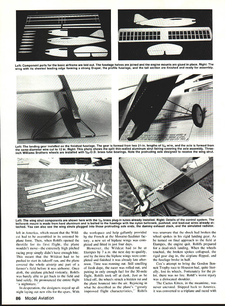
Landing gear
- Cut two 21-in. lengths of 3/32-in. wire. Center the wires in the brass tube fuselage mounts, then bend them down by hand until they are parallel and flush with the fuselage sides.
- Bend them back out until they are positioned at approximately 45° to the fuselage.
- Measure 6 in. from the fuselage, then bend each wire back under the fuselage and at right angles to it. You should have two triangles swinging from the mounts, with the tips of the wires just touching under the fuselage.
- Cut a 12-in. piece of 3/32-in. wire for the axle. Center it between the gear legs, then bind and solder securely.
- For a finished look, split an 8½-in. piece of streamlined, thin-walled aluminum strut material and epoxy it to the axle section.
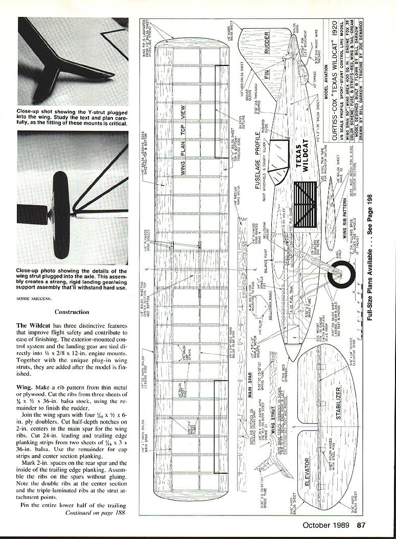
- Cut two 1-in. lengths of 5/32-in. brass tubing and slide them on the axle for wheel bearings. Carefully mount 3-in. Williams Brothers Golden Age wheels. About 1 in. of wire should remain on each axle for wing strut attachment—bend it back and up until it points directly at the wing strut plug points.
- Cut the Y-struts from 1/8-in. plywood, leaving them a little long for trimming to fit. Notch as shown on the plan and glue 1-in. long 3/32-in. brass tubes in place.
- Glue 1/16-in. plywood facings to the struts and trim to fit. Note that there are both right and left bevels at the attachment points.
- Bend four L-shaped attachment fittings from 3/32-in. wire. With the struts plugged into the axle, fit the four wire pieces to the Y-ends and mark the exact attachment points on the triple-laminated wing ribs. The mounting points should be approximately 3 in. apart, with the front point 2 in. from the leading edge. Drill the strut mounting holes and glue in 3/32-in. brass tubes.
- Finish sand, paint, and plug in the struts.
Control system
- Make a bellcrank mount from hard aluminum as shown on the plan.
- Bolt it, with nylon bellcrank, pushrod, and lead-out wires attached, to the fuselage.
- Use an adjustable threaded clevis to fasten the pushrod to the elevator control horn.
- Run lead-out wires through the line guide on the strut and form loops to attach the control lines.
Engine, muffler, and fuel system
- The prototype used a vintage .35 Fox engine (1954/55). If your engine lacks muffler mounts, clamp on a cut-down Du-Bro Muff-I-Aire.
- Using a 10 x 6 prop the Fox provides ample power; the muffler reduces noise somewhat.
- Clamp a 4-oz pressurized constant-flow fuel tank to the fuselage as indicated on the plan.
Flying
- Before the first takeoff, ensure all flying surfaces are warp-free and properly aligned.
- Balance the model at the center-of-gravity indicated on the plan. On the prototype, this was achieved by securing about 1/2 oz of lead on top of the lower engine mount with the mounting bolts.
- The Wildcat model is a smooth, nimble flier and a graceful stunter. It has no bad habits—unless you rediscover the consequences of a rigid landing gear like those encountered by Roland Rohlfs with the full-scale racer.
Transcribed from original scans by AI. Minor OCR errors may remain.

