
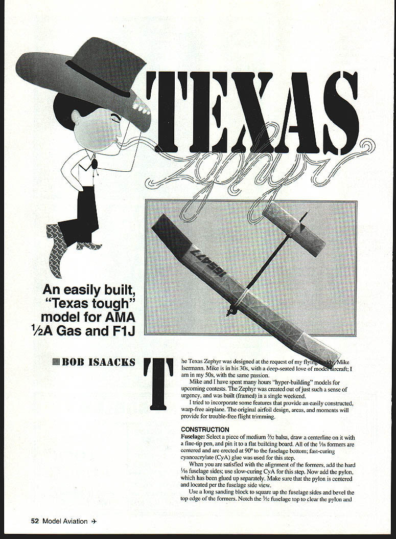
Texas Zephyr
An easily built, "Texas tough" model for AMA 1/2A Gas and F1J
Bob Isaacks
The Texas Zephyr was designed at the request of my flying buddy Mike Isermann. Mike is in his 30s with a deep-seated love of model aircraft; I am in my 50s with the same passion.
Mike and I have spent many hours "hyper-building" models for upcoming contests. The Zephyr was created out of just such a sense of urgency and was framed in a single weekend.
I tried to incorporate features that provide an easily constructed, warp-free airplane. The original airfoil design, areas, and moments will provide trouble-free flight trimming.
Construction
Fuselage
- Select a piece of medium 3/32" balsa, draw a centerline with a fine-tip pen, and pin it to a flat building board.
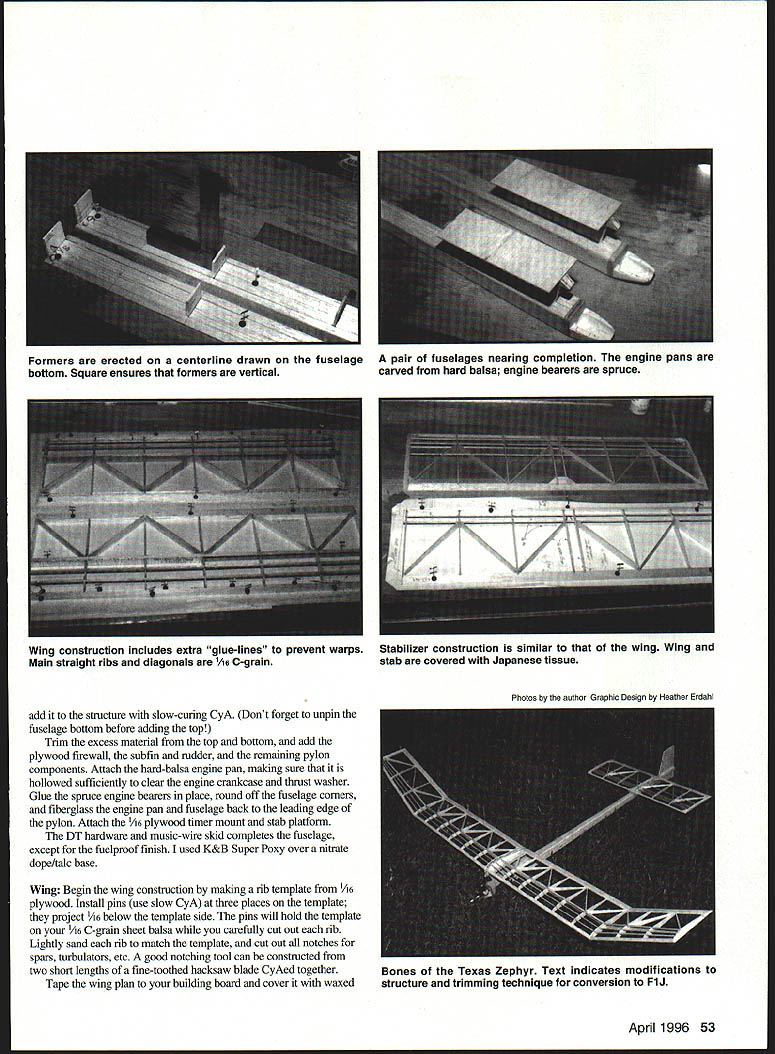
- Center the 1/16" plywood formers on the fuselage bottom and erect them at 90°. Use fast-curing cyanoacrylate (CyA) for this step.
- When satisfied with former alignment, add the hard 1/16" balsa fuselage sides using slow-curing CyA.
- Add the pylon (glued up separately). Make sure the pylon is centered and located per the fuselage side view.
- Use a long sanding block to square the fuselage sides and bevel the top edge of the formers. Notch the 3/32" fuselage top to clear the pylon. Unpin the fuselage bottom before adding the top.
- Trim excess material from top and bottom, then add the plywood firewall, subfin, and rudder.
- Attach remaining pylon components and the hard-balsa engine pan; hollow the pan sufficiently to clear the engine crankcase and thrust washer.
- Glue spruce engine bearers in place; round off fuselage corners.
- Fiberglass the engine pan, fuselage back, and leading edge of the pylon.
- Attach a 1/16" plywood timer mount/stab platform. Install DT hardware and the music-wire skid.
- Fuelproofing and finish: K&B Super Poxy over a nitrate dope/talc base was used.
Wing
- Make a rib template from 1/16" plywood. Install pins in three places and use slow CyA. Use the template on the plan; side pins will hold it.
- Cut ribs from 1/16" C-grain sheet balsa. Carefully cut and lightly sand each rib to match the template. Cut notches for spars, turbulators, etc.
- A good notching tool can be made from two short lengths of fine-toothed hacksaw blade CyAed together.
- Tape the wing plan to the building board and cover it with waxed paper.
- Glue up the leading edge and leading-edge filler. Glue the 1/16" sheet (grain vertical) TE cap to the front of the trailing edge. This construction provides a glue line to the leading and trailing edge components—a significant contribution to warp reduction.
- Glue in all 1/16" ribs (excluding the diagonals), utilizing 1/8" spacers to provide a secondary glue line at the trailing edge and extra gluing area for the ribs.
- Trim the front of the ribs in the rib section to provide the leading-edge sweepback.
- Add the 1/8" balsa dihedral break ribs, tilting them slightly to approximate angles required.
- Add spars, spar caps, webs, and turbulator spars. Then add diagonal ribs (rectangular strips of 1/16" balsa), carefully sanded to match the upper camber of the conventional ribs.
- Complete dihedral breaks as for a hand-launched glider wing: bevel the 1/4" ribs to achieve the correct angles and butt-glue the wing panels together using slow-curing CyA.
- Install soft-block wingtips, 1/8" gussets, and the 1/16" plywood dihedral brace.
- Carve and sand the leading edge to shape and give the wing a careful sanding in preparation for covering. Eliminate glue bumps or high spots that would interfere with smooth covering.
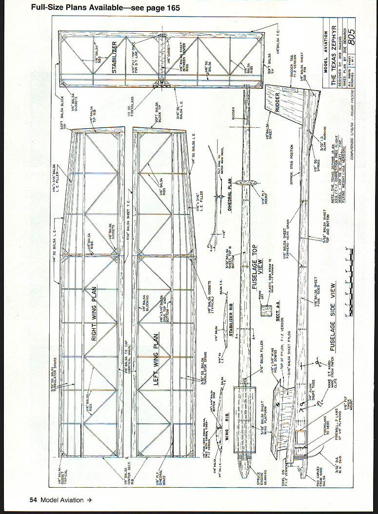
Note: Full-size plans are available (see original publication reference).
Stabilizer
- Cut stabilizer ribs using the same method as wing ribs. Notch the trailing edge with the prepared notching tool.
- Glue up the basic stabilizer assembly, including spars.
- Add diagonal ribs and soft-block tips.
- Add filler sheeting between the center ribs and finish-sand the stabilizer in preparation for covering.
Covering
- Give all surfaces to be covered three coats of full-strength nitrate dope, sanding lightly between coats.
- Apply Japanese tissue with thinned dope, then apply two finish coats of dope.
- Sand lightly if necessary to produce a smooth, fuelproof finish.
Flight Trimming
- After covering and dope cure, assemble the airplane and check carefully for warps.
- Each wingtip should have 1/8" washout (trailing edge higher than leading edge). The right main panel should have 3/16" wash-in.
- Because geodetic surfaces are difficult to warp, a five-inch strip of 3/16" TE stock reverse-glued to the right main panel was used to achieve the wash-in.
- The stabilizer should be absolutely flat. Do not fly until surfaces match these conditions.
- From the front, ensure the stabilizer is tilted parallel with the right main panel.
- Check that the center of gravity matches the plan. If nose weight is necessary, remove the timer and add clay behind the firewall.
- Find a field with high grass on a light/no-wind day for initial tests.
Test gliding and initial trim:
- Remove the prop and begin test gliding with a firm launch at an imaginary spot 50 feet in front of you.
- Correct stalling by removing packing from the rear of the stabilizer; correct diving by adding packing under the rear of the stabilizer in 1/16" increments.
- The Zephyr should tend to turn right; this is corrected by stabilizer tilt. If more shimming is required, add the same shim to both front and rear of the stabilizer. Go slowly—make only one change at a time.
First power flights:
- Use the prop on backwards at 90% power for first power flights. A five-second engine run should reveal flight trajectory.
- The Zephyr should climb out at approximately 60° with a definite turn to the right. A straight-up climb usually indicates a lack of incidence—correct by packing under the rear of the stabilizer.
- If the Zephyr goes "round" (like a loop on its side), remove packing under the rear of the stabilizer.
- Continue testing at 90% power, gradually increasing engine run time until the model is grooved with a ten-second engine run, adding shimming as required.
- Complete trimming by installing the prop correctly and going to full power. Reduce engine-run time to four seconds and observe the power pattern.
- The Zephyr should climb very steeply (about 85°) with a definite right turn. Continue shimming as necessary to control climb angle and turn.
- If the Zephyr straightens near the end of a 10-second run, add a slight right rudder tab. Think through each change and make only one adjustment at a time.
- When trim is optimized, disassemble and take the model to the next 1/2A contest. With its high-aspect-ratio wing and thin (7%) airfoil, the Zephyr gains altitude quickly—always light the DT fuse.
Good luck with your Zephyr. If you have questions concerning building or flying your version, write to me and enclose a stamped, self-addressed envelope. Thermals!
Changes for the F1J version
- Build the pylon lower (see dotted line on drawing) and build an engine cowl.
- Build in a tube (soda straw) for actuating lines in the fuselage (see section A-A for approximate location).
- Reinforce spar webs in the wing with carbon fiber (see drawing note).
- Install a hinged rudder tab (see drawing).
- Do not build in stabilizer tilt.
- Trim with wing and stabilizer at 0° incidence. Launch vertically. Use the rudder tab to initiate the glide pattern—this works better than a bungee. About 3/4 tab was necessary to achieve a good rollout. Best glide was achieved with about 3° negative on the stabilizer. Actuate glide trim on the stabilizer 1–1/2 to 2 seconds after engine cut.
Bob Isaacks 4335 Field Meadow Katy, TX 77449
Transcribed from original scans by AI. Minor OCR errors may remain.

