
Thinking Big
Jim Crawford
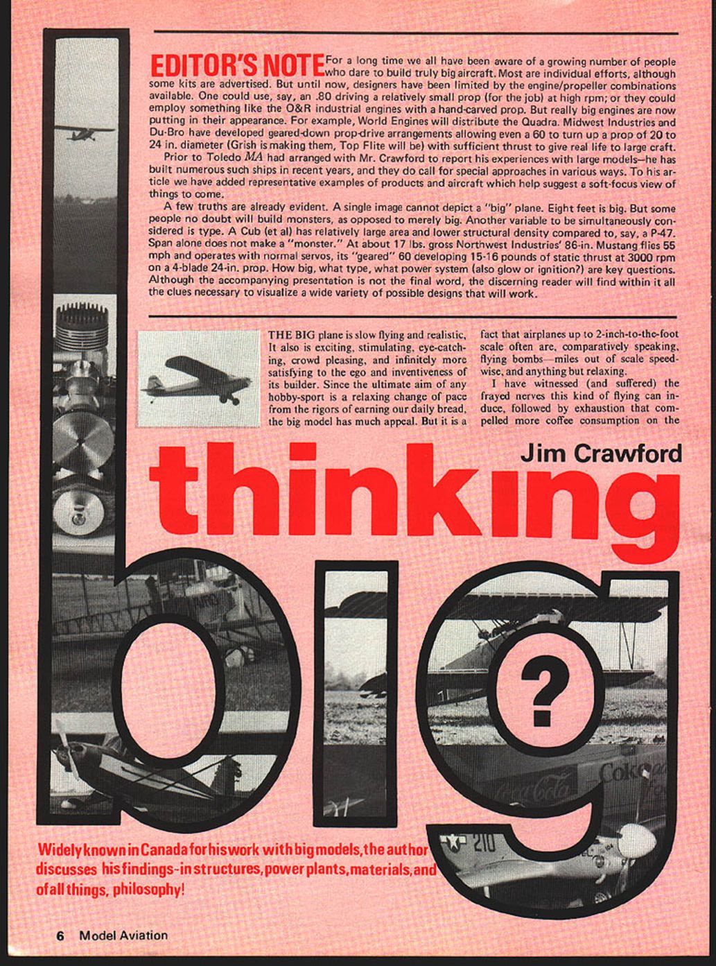
THE BIG plane is slow flying and realistic. It also is exciting, stimulating, eye-catching, crowd pleasing, and infinitely more satisfying to the ego and inventiveness of its builder. Since the ultimate aim of any hobby-sport is a relaxing change of pace from the rigors of earning our daily bread, the big model has much appeal. But it is a fact that airplanes up to 2-inch-to-the-foot scale often are, comparatively speaking, flying bombs—miles out of scale speedwise, and anything but relaxing.
I have witnessed (and suffered) the frayed nerves this kind of flying can induce, followed by exhaustion that compelled more coffee consumption on the
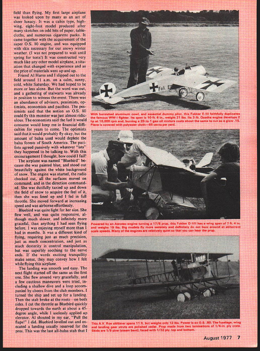
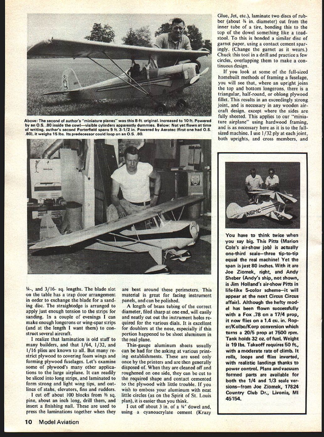
Widely known in Canada for his work with big models, the author discusses his findings — in structures, power plants, materials, and of all things, philosophy! field than flying. My first large airplane was looked upon by many as an act of sheer lunacy. It was a cabin type, high-wing, eight-foot model produced after many sketches on odd bits of paper, tablecloths, and numerous cigarette packs. It came together with the acquirement of the super O.S. 80 engine, and was equipped with skis necessary for our snowy winter weather. (I was not prepared to wait until spring for tests!) It was constructed very much like any other model airplane, a situation that changed with experience and as the price of materials went up and up.
Friend Al Harse and I slipped out to the field around 11 a.m. on a calm, sunny, cold, white Saturday. We had hoped to be more or less alone. But the word was out, and a gathering of stalwarts was already in position to witness the event. There was an abundance of advisors, pessimists, optimists, economists and pacifists. The pessimists said that the notion an O.S. 80 could fly this monster was just almost ridiculous. The economists said the fuel it would consume would keep me in financial difficulties for years to come. The optimists said that it would probably fly okay, but the amount of balsa used would deplete the balsa forests of South America. The pacifists agreed passively with whatever "ists" they happened to be talking to. With this encouragement I thought, how could I fail?
The airplane was named "Bluebird" because she was painted blue, and stood out beautifully against the white background of snow. The engine was started, the radio checked out, all the surfaces moved on command, and in the direction commanded. She was dutifully taxied up and down the field of snow to acquire the feel of it, then she was lined up and I fed in full throttle. She moved forward at increasing speed and was airborne effortlessly.
Bluebird was quite light for her size. She flew well, and was quite responsive, although much slower, and infinitely more graceful, than anything I had seen flying before. I was enjoying myself more than I had in months. It was a different kind of flying, requiring just as much precision, just as much concentration, and just as much dexterity in control manipulation, but was superbly soothing to the nerve ends. If the words exciting tranquility make sense, they may convey how I felt while flying this airplane.
The landing was smooth and easy. The next flight started off the same as the first one. She flew around very gracefully, and a few cautious maneuvers were tried, including a shallow dive and a loop accompanied by cheers from the club members. I turned the ship and set up for a landing. Then the stab broke at the roots—on both sides. I cut the throttle as Bluebird quickly dropped towards the earth at about a 45-degree angle, while I uselessly applied up elevator. Al shouted in my ear, "Pull the flaps!" I did. Bluebird levelled out and executed a landing usually reserved for the pros. This was the last all-balsa stab that I built. Big planes require different building techniques.
An examination of the broken stab made it obvious that balsa was not going to stand up to the stresses applied during even mild aerobatics, the surfaces being large in area compared to the section. Unless I used huge chunks of balsa that humiliated my sense of scale construction. Other ways had to be found.
The acquirement of several E.A.A. magazines (Sport Aviation) offered some light, and the methods used by the home-builder of full-sized airplanes opened a new door in building techniques. I purchased such magazines as Homebuilt and others that contained drawings and construction photographs. Enlightened by the techniques displayed, a new approach to the design and construction of large models became for me as exciting as the flying. I envisioned them as "miniature aircraft" rather than models.
For instance, I had spent hours devising the shock-absorbing landing gear necessary to preserve the nose on a model of this size, mainly adhering to the familiar techniques used with smaller models. This may have been suitable for the small models but was inadequate for planes spanning eight or nine feet or more. Now, a miniature copy of the J-3 type landing gear was easily achieved, and worked just as the real one did. Not only authentic, it was a necessity if the aircraft was to survive. A study of the J-3 landing gear and its function, plus a little thought, should enable you to produce a good workable duplicate.
Contrary to opinion, ordinary soft solder can be used in most of these units. I fabricate from stainless steel the fittings for attaching landing gears and wing struts. Hard brass or thin-gauge steel also has been used successfully. Another useful material is 1/4-in. thick-walled copper tubing, as sold in plumbing outlets. It is used to secure landing gear legs to the fuselage fittings. The copper tube is cut about 1/4-in. long, slotted at one end for about 3/8 in. down its length, flattened slightly, then filed round and drilled through the slots to take a nut and bolt. The tubing is then sweat soldered to the end of the landing leg for attachment to its appropriate fuselage fitting. "Bungee" cord can be suitable rubberbands. These in turn can be neatly covered in "canvas," as many of the real ones were. (See Spirit of St. Louis plan, June issue.)
The basic fuselage of the large model should be constructed from so-called hardwood. That this hardwood has to be spruce is a myth. I have used several types of woods, and find that a good straight-grained pine, and in some applications cedar, is an excellent substitute for the expensive and elusive Sitka spruce.
I built a saw table with a 3/4-in. ply top 2'6" by 6' in length. An ordinary 7-in. plywood blade was used for cutting the 3/8-in.
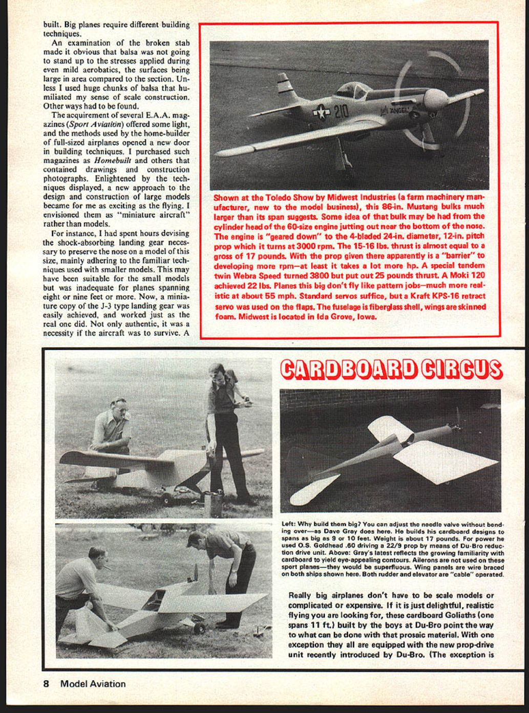
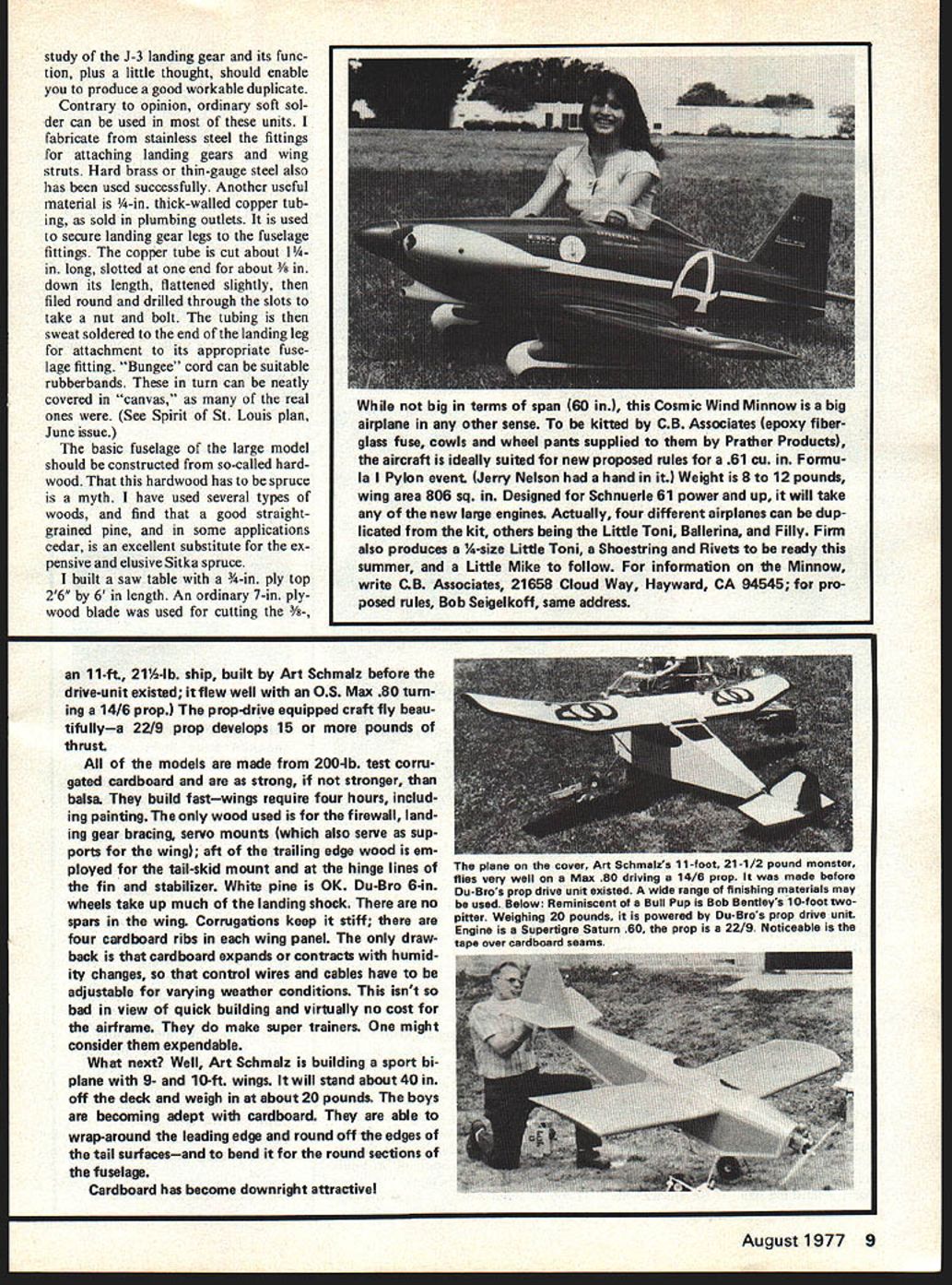
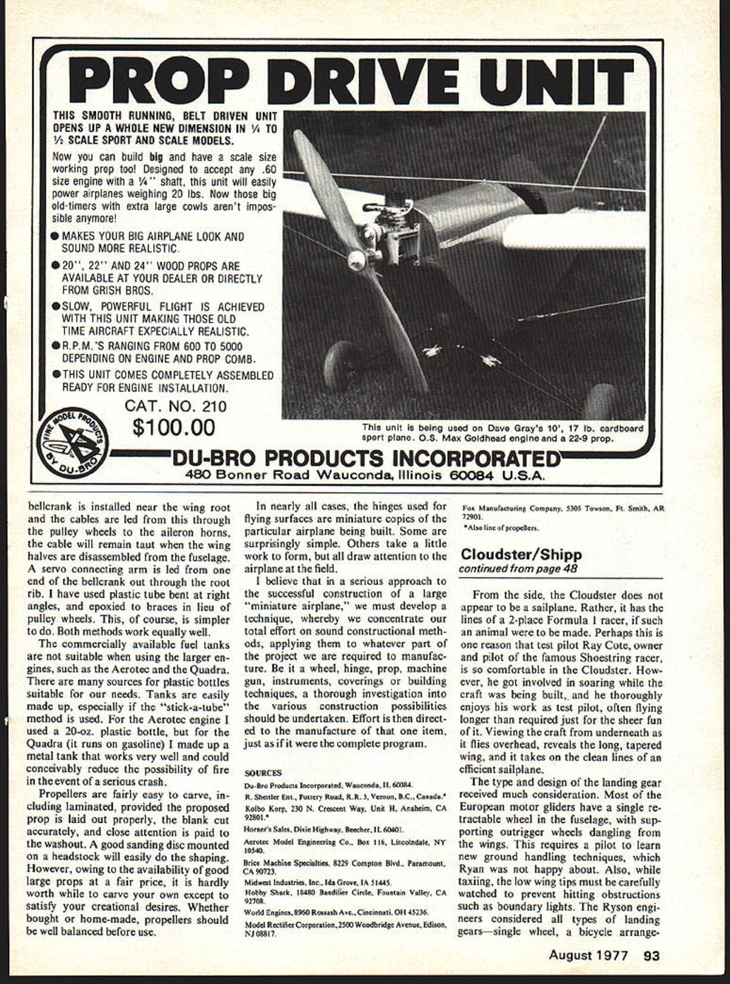
An 11-ft., 21-1/2-lb. ship, built by Art Schmalz before the drive-unit existed, flew well with an O.S. Max .80 turning a 14/6 prop. The prop-drive equipped craft fly beautifully—a 22/9 prop develops 15 or more pounds of thrust.
All of the models are made from 200-lb. test corrugated cardboard and are as strong, if not stronger, than balsa. They build fast—wings require four hours, including painting. The only wood used is for the firewall, landing gear bracing, servo mounts (which also serve as supports for the wing); aft of the trailing edge wood is employed for the tail-skid mount and at the hinge lines of the fin and stabilizer. White pine is OK. Du-Bro 6-in. wheels take up much of the landing shock. There are no spars in the wing. Corrugations keep it stiff; there are four cardboard ribs in each wing panel. The only drawback is that cardboard expands or contracts with humidity changes, so that control wires and cables have to be adjustable for varying weather conditions. This isn't so bad in view of quick building and virtually no cost for the airframe. They do make super trainers. One might consider them expendable.
What next? Well, Art Schmalz is building a sport biplane with 9- and 10-ft. wings. It will stand about 40 in. off the deck and weigh in at about 20 pounds. The boys are becoming adept with cardboard. They are able to wrap-around the leading edge and round off the edges of the tail surfaces—and to bend it for the round sections of the fuselage.
Cardboard has become downright attractive! 1/4-, and 3/16- sq. lengths. The blade slot on the table has a trap door arrangement in order to exchange the blade for a sanding disc. The straightedge is arranged to apply just enough tension to the strips for sanding. In a couple of evenings I can make enough longerons or wing-spar strips (and at the length I want them) to construct several aircraft.
I realize that lamination is old stuff to many builders, and that 1/64, 1/32, and 1/16 plies are known to all. But many restrict plywood to covering foam wings and forming plywood fuselages. Let's examine some of plywood's many other applications to the large airplane. It can readily be sliced into long strips, and laminated to form strong and light wing tips, and outlines of stabs, elevators, fins and rudders.
I cut out about 100 blocks from 3/8 sq. pine, about an inch long, drill them, and insert a finishing nail. These are used to press the laminations together when they are bent around these perimeters. This material is great for facing instrument panels, and can be polished.
A length of brass tubing of the correct diameter, filed sharp at one end, will easily and neatly cut out the instrument holes required for the various dials. It is excellent for doublers at the nose, especially if this portion happened to be sheet aluminum in the real plane.
Thin-gauge aluminum sheets usually can be had for the asking at various printing establishments. These are used only once by the printers and are then generally disposed of. When they are cleaned off and roughened on one side, they can be cut to the required shape and contact cemented to the plywood with little trouble. If you wish to emboss your aluminum with neat little circles (as on the Spirit of St. Louis plan), it is easier than you think.
I cut off about 3 in. of a 1/4" dowel and, using a cyanoacrylate cement (Krazy Glue, Jet, etc.), laminate two discs of rubber (about 3/8 in. diameter) cut from the inner tube of a tire, bonding this to the top of the dowel something like a toadstool. To this is bonded a similar disc of garnet paper, using a contact cement sparingly. (Change the garnet as it wears.) Chuck this tool in a drill and practice a few circles, overlapping them to make a continuous design.
If you look at some of the full-sized homebuilt methods of framing a fuselage, you will see that, where an upright joins the top and bottom longerons, there is a triangular, half-round, or oblong plywood fillet. This results in an exceedingly strong joint, and is necessary in any wooden aircraft design, except where the sides are fully sheeted. This applies to our "miniature airplane" using hardwood framing, and is as necessary here as it is to the full-sized machine. I use 1/32 ply at each joint, both uprights and cross members, and glue these fillets in place. feather the edges by sanding. This adds realism.
In an article in Canada's M.A.A.C. magazine, Dick Phillips stated he spent something like $20 in building the airframe of an eight-foot plane; it cost him $40 to cover it. I was shocked. The cost of the airframe used to be the consideration, the covering a comparative incidental. When I calculated the cost of covering an airplane this size using our known covering materials, it was ridiculous. The price asked for a yard of flimsy covering material was unbelievable. I thought over this covering material problem—application-wise, weight-wise and cost-wise—and the answer was nylon.
I purchased a few yards from a textile store and covered the airplane. The nylon brought the covering price to a sensible level. It was easy to work with, and doped well to the framework. The filling coats were clear dope, cut 50-50 with the usual amount of talcum powder added.
The best method to apply these first coats is to sponge them on. By this I mean cutting off a 6 X 4" piece from sponge rubber and dipping it into the dope and drawing it across the covering. The material fills quickly and evenly. However, nylon had some defects. One is small areas (about an inch square) that did not dope-fill. Another is its tendency to sag a little in damp weather, although it returns to normal when drier air is present. Then I discovered the world of polyesters.
This material is mostly used for lining drapes, coats, jackets, etc. At 65¢ a yard and 48 in. wide it was even cheaper than nylon. The only difficulty with this material was in applying it to the framework with dope. It tended to "spring up" in places. But what did work very well indeed was contact cement. You cut out your covering, then apply contact cement to the outer perimeter of your wing or fuselage section and lay on the polyester. Use a gel contact cement because the other stuff can be pretty stringy. You now can lift and stretch the polyester until you have a smooth and taut covering.
Now go over the cemented areas with a heat iron to cure the cement. When the covering is complete, let it stand for 24 hours and then pass your iron over all the surfaces, and the wrinkles, fold lines, and small creases will disappear. Don't iron too soon or you might draw the material from the cemented area and cause sagging.
Another product, usually found in drug stores, is a "Scotch-brand" hair-set tape produced by the 3M company. This item was originally intended to hold your wife's curls in place. The tape is pinked along both edges and is 30 ft. long by 1/2 in. wide, semi-sticky on one side.
For aircraft from around 1925 on, I used pinking tape to cover over rib stitching; and where two lengths of covering met, such as down the fuselage sides. Around the wing perimeter it is not only scale-like, but helps to hide any unevenness in the covering when it is trimmed. Pass your hot iron over the tape to insure a firm bond.
One problem was suitable wheels. They had to be large enough to suit the scale, be acceptably light, and functionally strong. I approached this problem from too many angles to list here. For smaller scale (2 in.-to-the-ft. WWI airplanes) I fabricated passable spoked wheels. My method for this appeared in Dave Platt's "Scale in Hand," RCM, August '69. However, as real spoked wheels were generally covered in canvas, or sometimes aluminum discs, I decided on a more practical approach. The result was a method by which any size or type could be produced, fulfilling the above requisites.
A drawing must be made of the proposed wheel, and from this an elevation, showing both sides of the wheel while looking at its edge—that includes the tire rim, the sides and the hub. This method re-
Thinking Big/Crawford
requires two slabs of wood at least 3/4 in. larger than the circumference of the wheel, and at least 1 1/2 in. thick. Chuck this to the faceplate of a wood lathe and mark out the tire rim section, and the hub. You can turn the shape required into the wood, forming one side of the wheel, and when finished, you should have the plugs corresponding to the outside shapes of the required wheel.
In some wheel types both sides are identical and, therefore, only one plug would be required. Sand, wax, and polish the plugs and lay up with sufficient fiberglass and resin, depending on the type and size, to form the wheel sides. When set up, remove and lay up the second one. Now trim the excess glass to the tire rim and sand down the edges. Drill the axle holes and put the two halves together, then measure the exact distance between both faces, where the holes are located. A small sliver of wood through one hole and touching the opposite face, will give you the correct distance, allowing for the fiberglass thickness.
How true the wheel turns, depends upon your accuracy in lining up the axle. I have used broomstick, cut to fit between the holes, as the hub. This, in turn, is drilled and a brass tube shaft inserted. Allow the brass tube to project from both sides of the wheel. When you have the hub in place, resin well. The two rim edges will now come together; these are resined and wrapped a couple of times with fiberglass tape. When the resin is set up, cut off the protruding brass tube about 1/8 in. clear of the wheel hub. Make several saw cuts across the ends of the protruding tubes and tap down the segments around the hub perimeter. The whole wheel can now be sanded smooth; a length of dowel through the axle hole will help at this point.
The tires are cut from rubber tubing, or the circular sponge rubber used in industry for expansion joints. Measure and cut the tire carefully for a tight fit, and cement the two ends together with cyanoacrylate. When the tires are mounted, a drop of this glue around the perimeter of the tire and rim will insure a close relationship.
On airplanes using cables for the controls, a superb substitute is dial cord, sold at many radio accessory outlets. One method I use to install these cables, is to make up two small wooden blocks, drilled halfway in, and epoxied on each side of the fuselage for bearings. Between these is a length of brass tube (generally 3/16) which carries a bellcrank; fit the tube into the blocks before you epoxy them in. The bellcrank is vertical and in line with the center of the fore-and-aft line of the fuselage. The tubing is provided with an arm on one side; that in turn carries the connecting arm to the servo. This allows the elevator cables to run down the center of the fuselage, while the servo is mounted at one side, and also allows the rudder servo to be mounted on the centerline.
I have found it helpful to put a little tension on the elevator crank to assist the servo in pulling the elevator to the up direction. A rubberband will suffice; make sure that it does not overload the servo. The Baby Ace (it was 9 feet, and each rib was built up from 1/8 sq. spruce) had cable-operated ailerons—as did the full-size machine—that ran through small pulley wheels.
I duplicated this plane from full-size plans, including aluminum wing tips, and aluminum-sheeted leading edge. If a large bellcrank is installed near the wing root and the cables are led from this through the pulley wheels to the aileron horns. The cable will remain taut when the wing halves are disassembled from the fuselage. A servo connecting arm is led from one end of the bellcrank out through the root rib. I have used plastic tube bent at right angles, and epoxied to braces in lieu of pulley wheels. This, of course, is simpler to do. Both methods work equally well.
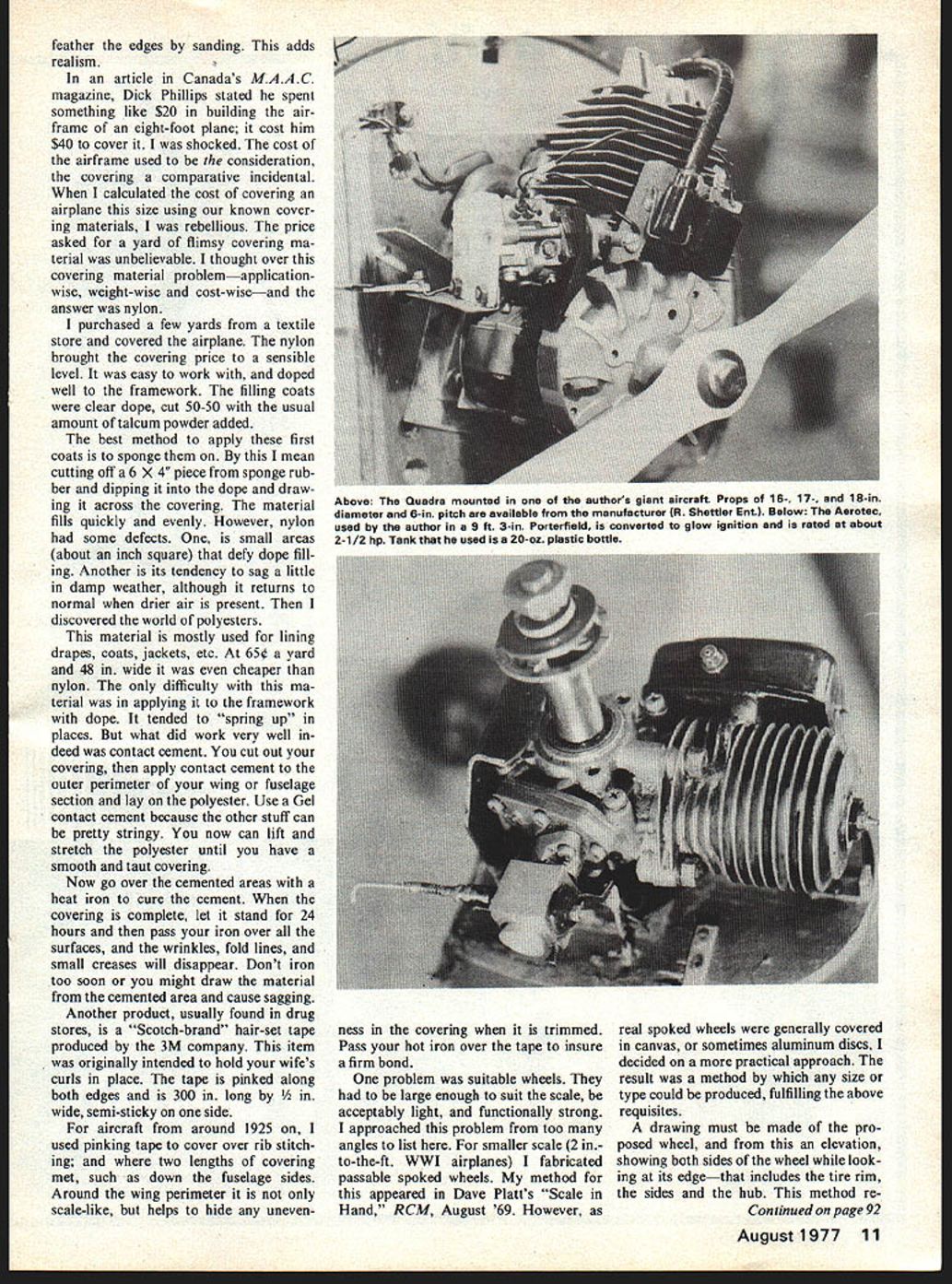
The commercially available fuel tanks are not suitable when using the larger engines, such as the Aerotec and the Quadra. There are many sources for plastic bottles suitable for our needs. Tanks are easily made up, especially if the "stick-a-tube" method is used. For the Aerotec engine I used a 20-oz. plastic bottle, but for the Quadra (it runs on gasoline) I made up a metal tank that works very well and could conceivably reduce the possibility of fire in the event of a serious crash.
Propellers are fairly easy to carve, including laminated, provided the proposed prop is laid out properly, the blank cut accurately, and close attention is paid to the washout. A good sanding disc mounted on a headstock will easily do the shaping. However, owing to the availability of good large props at a fair price, it is hardly worth while to carve your own except to satisfy your creational desires. Whether bought or home-made, propellers should be well balanced before use.
In nearly all cases, the hinges used for flying surfaces are miniature copies of the particular airplane being built. Some are surprisingly simple. Others take a little work to form, but all draw attention to the airplane at the field.
I believe that in a serious approach to the successful construction of a large "miniature airplane," we must develop a technique, whereby we concentrate our total effort on sound constructional methods, applying them to whatever part of the project we are required to manufacture. Be it a wheel, hinge, prop, machine gun, instruments, coverings or building techniques, a thorough investigation into the various construction possibilities should be undertaken. Effort is then directed to the manufacture of that one item, just as if it were the complete program.
SOURCES
- Du-Bro Products Incorporated, Wauconda, IL 60084.
- R. Shetler Ent., Pottery Road, R.R. 3, Vernon, B.C., Canada.*
- Kolbo Korp, 230 N. Crescent Way, Unit H, Anaheim, CA 92801.*
- Horne's Sales, Dixie Highway, Beecher, IL 60401.
- Aerotec Model Engineering Co., Box 116, Lincolndale, NY 10540.
- Brice Machine Specialties, 8729 Compton Blvd., Paramount, CA 90723.
- Midwest Industries, Inc., Ida Grove, IA 51445.
- Hobby Shack, 14880 Bairdshire Circle, Fountain Valley, CA 92708.
- World Engines, 8960 Roesch Ave., Cincinnati, OH 45236.
- Model Rectifier Corporation, 2500 Woodbridge Avenue, Edison, NJ 08817.
- Fox Manufacturing Company, 5305 Towson, Ft. Smith, AR 72901.
*Also line of propellers.
Transcribed from original scans by AI. Minor OCR errors may remain.

