
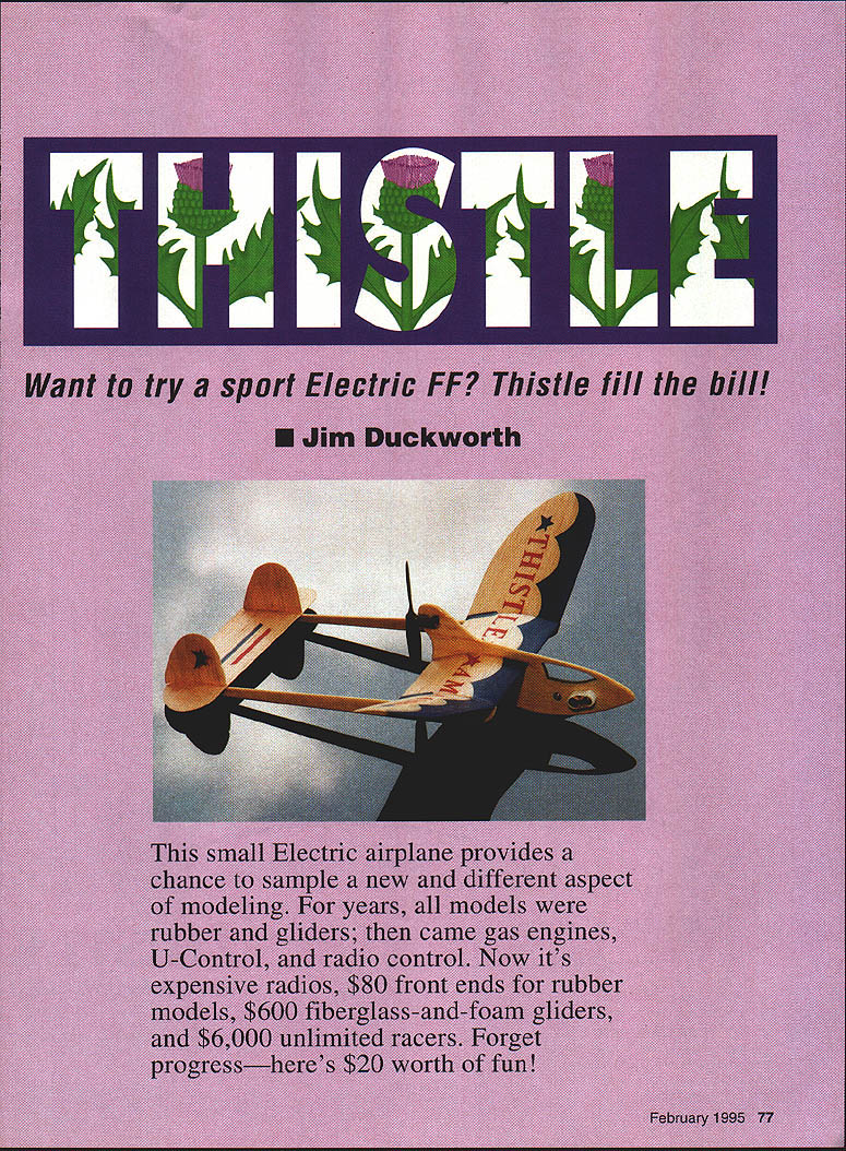
Thistle: Want to try a sport Electric FF? Thistle fills the bill!
Jim Duckworth
This small electric airplane provides a chance to sample a new and different aspect of modeling. For years, all models were rubber and gliders; then came gas engines, U-Control, and radio control. Now it’s expensive radios, $80 front ends for rubber models, $600 fiberglass-and-foam gliders, and $6,000 unlimited racers. Forget progress—here’s $20 worth of fun!
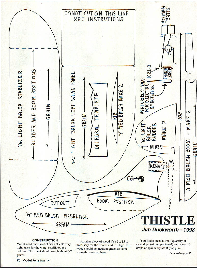
CONSTRUCTION
You’ll need one sheet of 1/32" x 3" x 36" very light balsa for the wing, stabilizer, and rudders. This sheet should weigh about 6–7 grams.
Another piece of wood, 1/8" x 3" x 15", is necessary for the booms and fuselage. This wood should be medium grade, as some strength is needed here.
You’ll also need a small quantity of clear dope (nitrate preferred) and about 10 drops of cyanoacrylate (CyA) glue.
Tools required include an X-Acto knife with a #11 blade; a small piece of 180–200 grit sandpaper; a steel straightedge; a smooth cutting surface; and a pencil. With all the materials on hand, construction should take about an hour.
A word about the Kenway motor: it is quite simple and well made, but I feel certain it would not stand the abuse of landings that allow the prop to hit the ground first. The power available from this motor is adequate for these small aircraft, but any bent shafts or out-of-alignment props will seriously affect the power output. I’m sure the motor could be disassembled, but getting everything to work after attempting to straighten the shaft might prove a formidable task. The pusher configuration of this model protects the motor quite well.
Plans are unnecessary; just trace the parts directly onto the balsa using the templates. Lay the wing template on the 1/32" sheet and trace around it. Mark the centerline and the dihedral break (indicated by marks on the template). Flip the template over, guide it on the centerline, and trace and mark again.
The stab and rudders are traced on the same sheet. Mark the rudder positions on the stabilizer, using the marks on the template. These lines also indicate where the booms attach. The grain should be spanwise on the stab and vertical on the rudders. Be sure your knife has a sharp #11 blade, and cut these parts out. Sand with very fine sandpaper until the edges start to get thin. You can hold the parts up to the light and see this effect. Remember, you are building an airframe that will weigh about 10 grams, so handle things gently and go slowly to avoid breaking the light balsa parts.
Now it’s time to “build” the airfoil into the wing. This airfoil is what we used to call a “zip” airfoil. Early zip airfoils were made by tracing the edge of one’s shoe sole, or anything handy that looked like an airfoil. (All you scientific types, count to ten before you say anything; it does work.) Wipe the top of the wing with a slightly damp cloth; this will expand the fibers on top. Put one coat of very thin clear dope on the bottom of the wing; the dope will shrink the fibers on the bottom. The wing will then have a slight curve. I use a hair dryer to speed this process, and by doing this I can manipulate the wing so it doesn’t warp spanwise.
Once you are satisfied that the wing has a reasonable curve, put a second coat of dope on the bottom, then a coat on the top. When you are done you should have a curved “airfoil” and the wing should not have any spanwise twists.
The booms are made from 1/8" medium balsa. The dimensions are 10-1/2" x 5/8" tapered to 1/4". You can make two booms from one piece 10-1/2" x 3/8" by making a cut from the 5/8" mark on one end to the 1/4" mark on the other end. With the remainder of the 1/8" wood, trace around the fuselage and cut it out again with a nice sharp blade. Don’t forget the cutout for the canopy, as this gives the Thistle a lot of “personality” when the light shines through it while airborne. The curved fuselage cut that will receive the wing should be made very carefully, with either a knife, jigsaw, or bandsaw. Challenge yourself not to break the fuselage at the front, where there is very little material. (If you do break it, no big deal; lay it on waxed paper and glue it with some CyA, and it will be stronger than it was originally.)
Some sanding of the booms and the fuselage should give them a nice finished appearance. Cut the two ribs that go under the dihedral break, and you’ve made yourself a kit! Now assemble these pieces into a flying machine:
- Cut the wing at the two dihedral breaks. Slip the center section into the cut in the fuselage. The curve of your wing may not be an exact match for the cut in the fuselage, but work the wing into the slot and hold it together with one hand while you line it up from the top as well as from the side.
- Push a straight pin in from the bottom, through the fuselage, and up through the wing at the rear. This should hold things while you line up the wing and fuselage. A little thin CyA along the wing–fuselage joint will make things permanent.
- Make the angle on the outer wing panel for the dihedral break by placing the dihedral template on the edge of the outer wing panel where you cut it away from the main wing section. Trace the curved line and cut on it. This will allow the center wing panel and the tip panel to come together, forming the proper dihedral. Some light sanding will assure that the two surfaces meet properly.
- The outer panel should have 1-3/4" dihedral. Thin CyA holds the wing panels together. Check that the wings have the same dihedral. Sand the rib pieces so they have the same curvature as the wing and glue them in place under the wing dihedral break. These ribs should be centered on the break and parallel with the direction of flight. Sand the bottom of these ribs to receive the booms.
- Pin the booms in place, making sure they are square with the wing and parallel with each other. When viewed from the side, the booms should be even. Attach the stabilizer on top of the booms, using the guidelines drawn on the stabilizer. Use pins to hold things in place, check the alignment, then CyA these pieces together.
- Attach the rudders, making sure they are perpendicular to the stabilizer. Check everything over and make any corrections necessary, which might mean using debonder to soften the CyA glue.
Give the entire model a very thin coat of dope to protect it from moisture. Cross your fingers and weigh the airframe. A small postal scale should be able to tell you how close you came to a weight of 10 grams.
Thistle
- Type: FF Electric Sport
- Wingspan: 14 inches
- Motor size/type: Kenway KR-1D or Micro 4
- Weight: 10 grams (airframe only)
- Construction: Solid balsa
- Covering/finish: Nitrate dope
MOTOR AND BATTERY INSTALLATION
Installation of the motor and the batteries begins by pushing the motor into position on the fuselage. Thick CyA can be used to hold the motor to the fuselage. Model aircraft cement, epoxy glue, or fast-curing epoxy can also be used. (I do not advise using thin CyA for this—it might run into the motor!)
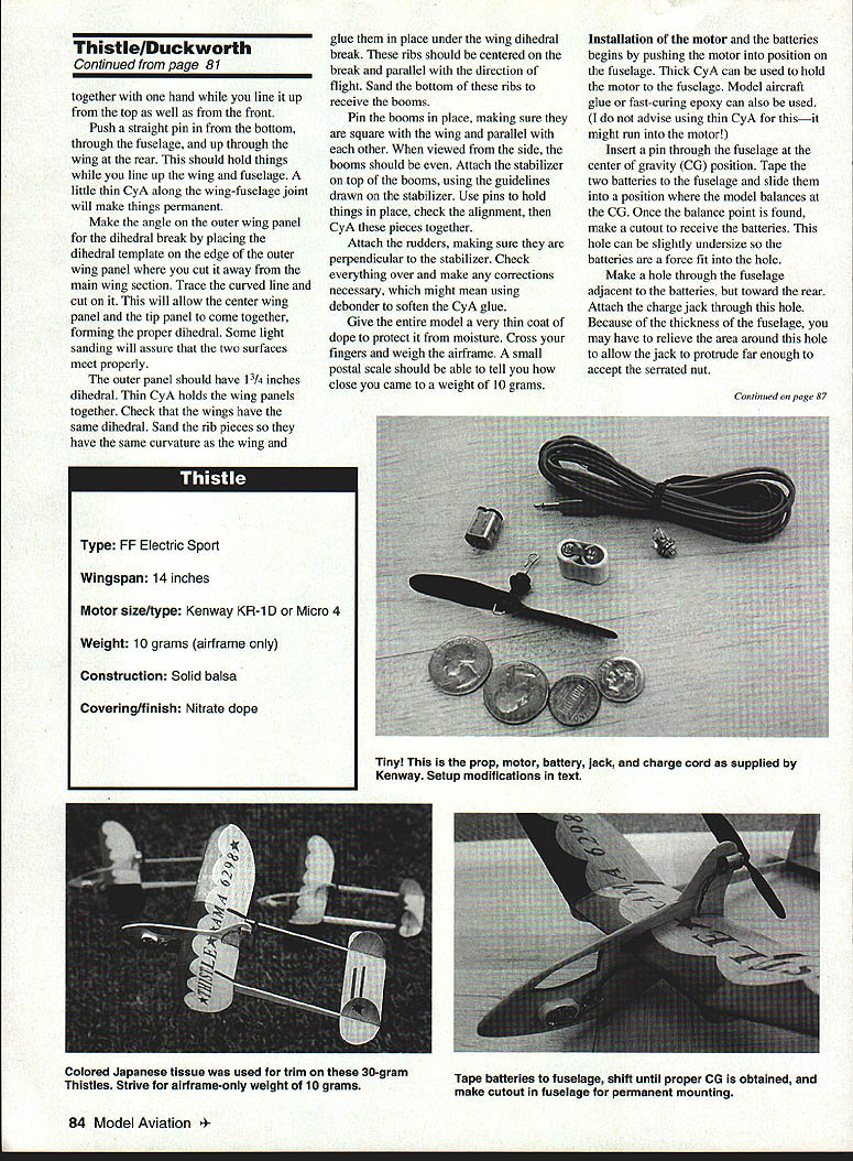
Insert a pin through the fuselage at the center of gravity (CG) position. Tape the two batteries to the fuselage and slide them into a position where the model balances at the CG. Once the balance point is found, make a cutout to receive the batteries. This hole can be slightly undersize so the batteries are a force fit into the hole.
Make a hole through the fuselage adjacent to the batteries, but toward the rear. Attach the charge jack through this hole. Because of the thickness of the fuselage, you may have to relieve the area around this hole to allow the jack to protrude far enough to accept the serrated nut.
Make up the wire that goes from the batteries to the charge jack to the motor. I use #28 wire, about seven inches long, color-coded red and black. Make a hole through the wing next to the fuselage to allow the connection between the battery system and motor.
Solder your system together using the schematic depicted on the template sheet. The contacts on the motor are the last items soldered.
At this time it is necessary to establish the proper rotation of the prop. This being a pusher setup using a tractor prop, the normal direction of rotation needs to be so that when you are looking at the prop from the rear, the prop rotates in a clockwise manner.
To balance the prop, place a straight pin through the motor shaft hole. The heavy blade can be lightened by scraping with an X-Acto blade held vertically against the flat side of the prop, or by adding layers of clear dope to the light blade until the prop balances. The prop must be in balance with this system, or the aircraft will shake violently and the available power will be greatly reduced.
The prop should be pushed on the motor shaft with the flat side of the prop toward the rear. If it feels as though the prop does not fit snugly on the shaft, you can use a piece of insulation from a small wire as a bushing in the shaft hole. The shaft hole can be reamed out to accept this bushing.
With this setup the prop will not fly off the shaft, but will force itself onto the shaft, due to the pusher configuration. Do not force the prop against the motor housing; leave a small clearance.
CHARGING SYSTEM
You can use three alkaline batteries soldered in series, or three 1200 mAh Ni-Cd cells soldered in series. When new, the alkaline system can overcharge the two cells, and the charge times should be reduced during early use. Three rechargeable Ni-Cds work fine; just solder up the plug and wire supplied with the Kenway motor. Double-check the polarity to make sure you do not reverse-charge the flight batteries.
You will want to have a dummy plug to insert in the jack on the aircraft to kill the motor after charging, unless you fly immediately. Radio Shack usually has these jacks in stock.
Put a small charge in the batteries and hold the leads against the motor contacts to determine the direction of rotation. Final solder connections to the motor are made with a very small soldering iron.
I use three 1200 mAh Ni-Cds in series. In order for this system to interface with the rest of my electric charging, I brought the positive and the negative out of the charge pack three inches and soldered a Dean’s female connector to them. The charger cord supplied with the Kenway is then equipped with a Dean’s male connector.
I “break” the charge wire at this point, when timing the charge to the flight batteries, and the charge cord is left dangling to serve as a dummy plug until I pull it out to fly. This lets me charge the 1200 mAh cells with my regular charge system for larger aircraft.
With the 1200 mAh cells fully charged, a charge time of 45 seconds seems to give 80 to 90 seconds of flight, depending on the conditions and how the aircraft is trimmed. It is important that you use some method of timing your charge to the flight cells. Counting in my head (one-thousand-one, one-thousand-two, etc.) works for me.
I don’t believe that the small cells can be damaged with just three Ni-Cd cells as a charge source; the voltage will equalize between the two packs before the small cells can vent or get too hot. This system can ruin the flight batteries if you try to charge with more than three cells.
FLYING
The Thistle has 0° difference between the wing and stab—it glides flat and fast. Mine carries about 1/32" up on the trailing edge of the elevator.
As far as turns go, you are on your own. These wings always have a “set,” and this will usually determine which direction your model will fly.
You will need to go through the tried-and-true method of test gliding over tall grass. Be careful—the model will lose any confrontations with fence posts and trees. You want a long, flat glide. Note any tendencies, and if severe, use a rudder tab to correct.
Power testing begins with a very small charge on the batteries; pull the charge jack and wait till the motor is winding down, then try your glide. Wait the turn to be sure it is not going to get too steep once under power.
Try it again utilizing more of the power charge, but not up to full power. You want a gentle circle about 30 feet across.
For the way I fly—“late-evening-stay-on-the-field”—I like the power and the glide pattern to be the same. It takes less “wide open spaces” if I use a pattern of left–left or right–right.
I usually work with whatever turn the craft seems to favor, and then use everything at my disposal (rudder trim, aileron trim or wing warp, wing weight, stab tilt, and thrust adjustments) to come to a flight pattern that will let the craft circle up and circle down, using minimum real estate.
Fly this model outdoors in absolutely quiet air. You will lose this aircraft if you try to fly it with any lift in the vicinity. I have been averaging 70–80 second flights in evening air.
A discouraging aspect to any of the very small aircraft is that after a nice flight, the landing often turns into a “flop in the grass,” with the model turning end-over-end. Phooey on this! The pusher configuration ensures that the model will often land in an upright position, and many times it will crease its way to a perfect landing. On asphalt or a smooth landing surface, it will sometimes bounce, become airborne again, and then settle in for a nice landing. When this happens, it makes your day!
There is another motor that works very well with this design: the Micro 4 motor will fit in the plane with just a few grams’ weight penalty, and a slight modification to the motor pylon. The performance with this motor will have you chasing the Thistle all over the county.
The first Thistle had a Micro 4, and I knew as I chased it on that first flight from our five-acre RC field (beyond a grove with 60-foot pecan trees, over a 40-acre peach orchard, and finally landing about 3/4 mile from the launch point) that my flying with the Micro 4 would be reserved for those times when I had some very young chasers at hand! With the Micro 4, you can expect some very impressive performance. Don’t forget your name-and-address label!
The day I test-flew the first Thistle was a bright, clear fall day with a very light wind. The light breezes were picking up insects, spider webs and thistles—hence the name. These inexpensive, small electric models can be very rewarding, and I hope yours gives you much pleasure.
- Kenway Motor: Kenway, Box 889, Hackettstown, NJ 07840.
- Micro 4 Motor: HiLine, Box 11558, Goldsboro, NC 27532.
- Contest Balsa: Sig Manufacturing Co., Montezuma, IA 50171.
Transcribed from original scans by AI. Minor OCR errors may remain.

