
Thomas-Morse MB-7
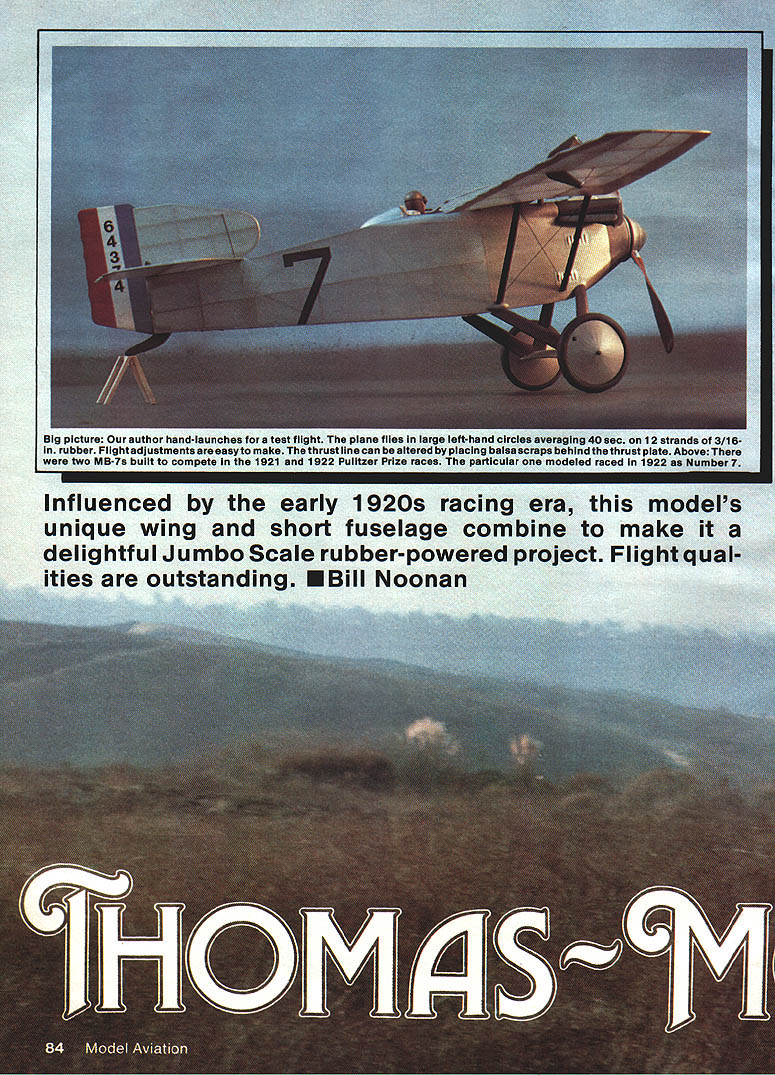
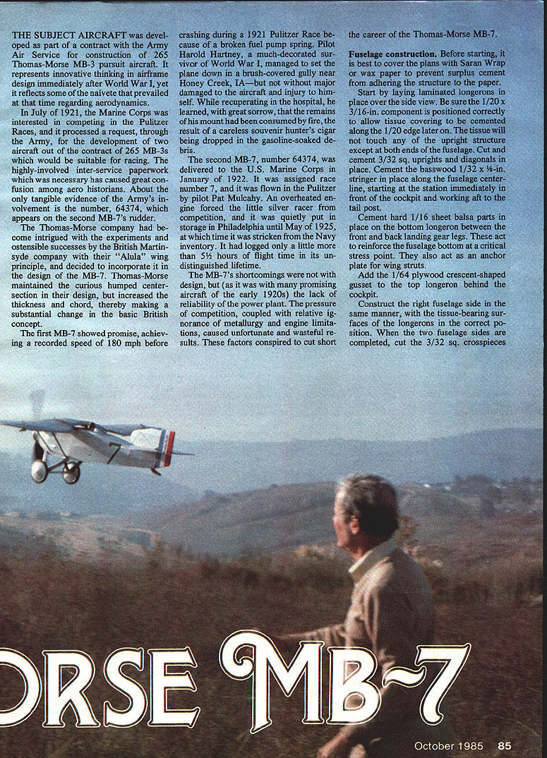
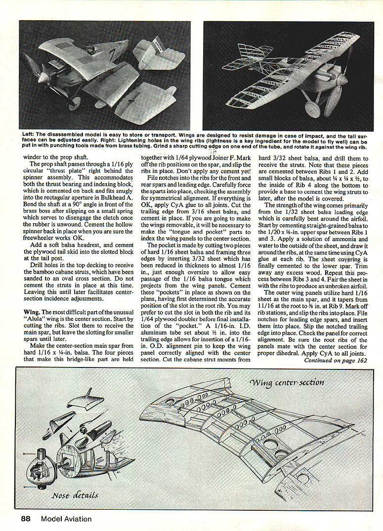
Influenced by the early 1920s racing era, the Thomas-Morse MB-7 combines a unique wing and short fuselage to make an attractive Jumbo Scale rubber-powered project. Flight qualities are outstanding.
The MB-7 was developed from an Army Air Service contract for construction of Thomas-Morse MB-3 pursuit aircraft and reflects innovative post–World War I airframe thinking (and some contemporary naivete about aerodynamics). In July 1921 the Marine Corps requested, via the Army, development of two aircraft from the MB-3 contract suitable for the Pulitzer Races. Inter-service paperwork has made the details confusing; tangible evidence of Army involvement appears only as the number 64374 on the second MB-7's rudder.
Thomas-Morse adopted and modified the British Martinsyde "Alula" wing principle, retaining a humped center section but increasing thickness and chord. The first MB-7 showed promise, reaching a recorded 180 mph before crashing in the 1921 Pulitzer Race due to a broken fuel-pump spring. Pilot Harold Hartney managed a forced landing but the aircraft was later destroyed by fire. The second MB-7 (No. 64374) was delivered to the U.S. Marine Corps in January 1922, assigned race number 7, and flown by Pat Mulcahy; an overheated engine ended its competition career, and it was placed in storage until stricken from the Navy inventory in May 1925 after logging just over 5½ hours. The MB-7’s shortcomings were primarily power-plant reliability and metallurgy limitations common to many early-1920s racers.
Fuselage construction
Before starting, cover the plans with Saran Wrap or wax paper to prevent surplus cement from sticking the structure to the paper.
- Lay out laminated longerons over the side view, ensuring the 1/20 x 3/16-in. component (positioned so later covering can be cemented along its 1/20 edge) is correct. The tissue will contact upright structure only at both ends of the fuselage.
- Cut and cement 3/32-in. square uprights and diagonals in place.
- Cement a 1/32 x 1/2-in. crossboard/stringer along the fuselage centerline, starting at the station immediately in front of the cockpit and working aft to the tail post.
- Cement hard 1/16-in. sheet balsa reinforcing parts to the bottom longeron between front and rear landing gear legs. These reinforce the fuselage bottom at a critical stress point and act as anchor plates for the wing struts.
- Add a 1/64-in. plywood crescent-shaped gusset to the top longeron behind the cockpit.
- Construct the right fuselage side in the same manner, keeping tissue-bearing surfaces correctly oriented. When both sides are completed, cut 3/32-in. square crosspieces to length and cement them in place, checking symmetry and taper toward the nose as shown on the plans. Cement crosspieces in place aft of the cockpit, then temporarily clamp and cement the tail posts together.
- Carefully cut upper and lower longerons to station (a fine-tooth saw helps). Cement front fuselage frames back in place, noting the taper to the nose, then cement crosspieces and the circular nose bulkhead.
- Carve the top cowl decking from soft balsa, hollowing it to about 1/8-in. wall thickness (work slowly). Use side formers B through E to check fair-ins as the fuselage sides are assembled. Remember the sides are covered with 1/32-in. sheet balsa; allow clearances for fitting side formers and the rear wing strut.
- Carefully cut the cockpit opening in the top decking (maintain elliptical symmetry). Cut 1/32-in. sheet balsa cowl sides slightly oversize, trim-to-fit against the fuselage, and cement in place (CyA works well). Wetting the outside of the sheet with an ammonia-and-water solution makes the wood more malleable for forming.
Engine and cowling details:
- Carve valve-cover assemblies from light balsa as single-piece units; separate trailing fairings are cone-shaped and leading fairings have vertical grain.
- Cut exhaust collectors from 1/16-in. sheet balsa and sand streamlined. Form the crossover from soft 1/16-in. sheet and add a hard-balsa breather pipe on top of the carburetor intake.
- Before adding the solid balsa lower cowling, bend the landing-gear legs from 1/32-in. wire (bend them as a single unit if possible). Bind crosspieces and fuselage wire thread and apply cement; add reinforcing gussets where crosspieces contact longerons.
- Cut a .045-in. wire spreader bar about 7 in. long and solder V fittings from the landing-gear legs to it.
Landing gear and fairings:
- Fit-in sheet-balsa streamline leg fairings so both ends fit neatly; fairing is built up like a small wing and cemented over the wire.
- Wheels: 3/4-in. diameter wheels may be turned from balsa in two pieces laminated at right angles or purchased commercially.
- Add a streamlined teardrop fairing at the junction of rear landing-gear leg and wing strut after covering the model.
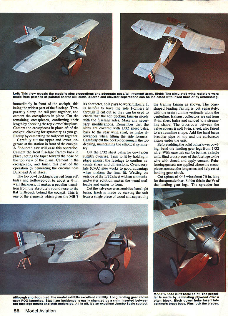
- The MB-7’s long landing gear makes ROG launches easy and contributes to stability.
Propeller and spinner (see separate subheading for full detail).
Finish fuselage assembly:
- Add a soft balsa headrest and cement the plywood tail skid into the slotted block at the tail post.
- Drill holes in the top decking to receive bamboo cabane struts (sand to an oval cross section). Do not cement struts in place yet—leave them removable to facilitate center-section incidence adjustments.
- Insert laminated plywood over the pitch block at the nose for local reinforcement.
Propeller and spinner
- The propeller is laminated plywood over a pitch block; blades are two pieces of 1/64-in. plywood laminated over the block (this makes blade replacement easy and allows pitch variation).
- The prop boss is 3/4-in. I.D. brass, drilled to accept a 1/16-in. shaft. The spinner is made by laminating six pieces of hard 1/4-in. sheet balsa at right angles to form a cube, then drilling and turning on a drill press or hand drill. Hollow the bullet-shaped nose to accommodate a freewheeling clutch.
- Insert the brass boss tube into the balsa disc and cement; add a 1/64-in. circular plywood doubler on the back for strength.
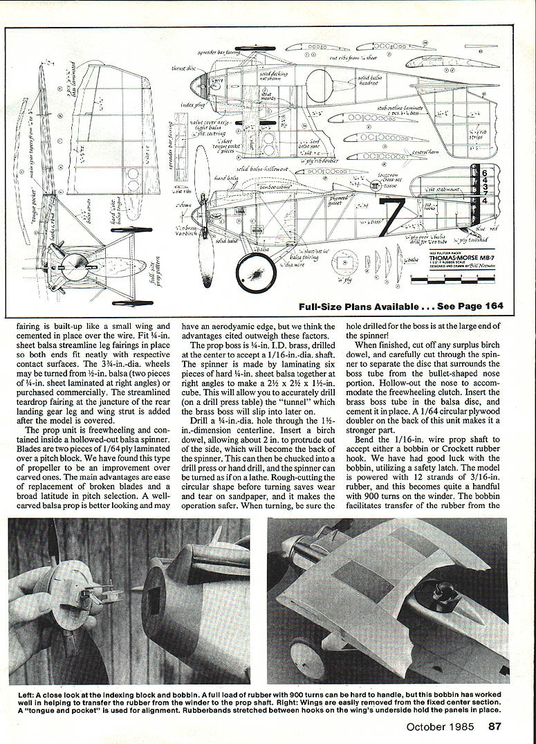
- Bend the 1/16-in. wire prop shaft to accept either a bobbin or Crockett rubber hook; a bobbin with a safety latch is recommended. The prop shaft passes through a 1/16-in. ply circular thrust plate behind the spinner to accommodate the thrust bearing and an indexing block that fits Bulkhead A.
- Slip a small spring onto the shaft and bend the shaft at 90° in front of the brass boss to disengage the clutch once the rubber is unwound. Cement the hollow spinner back in place after verifying the freewheeler works.
Power train:
- The model as built uses 12 strands of 3/16-in. rubber, about 36 in. long. This can be handled on a winder with a bobbin and safety latch.
Wings
The most difficult part of the unusual "Alula" wing is the center section.
Center section construction:
- Cut ribs and slot them to receive the main spar; leave slotting for smaller spars until later.
- Make the center-section main spar from hard 1/16 x 3/4-in. balsa. The four pieces that form this bridge-like spar are held together with a 1/64-in. plywood Joiner F. Mark rib positions and slip ribs in place but do not cement.
- File notches in the ribs for front and rear spars and the leading edge. Force spars into place, check symmetry, then apply CyA to all joints.
- Cut the trailing edge from 3/16-in. sheet balsa and cement in place.
- If making wings removable, create "tongue and pocket" registration parts: pockets from hard 1/16-in. sheet balsa framed with reduced-thickness 3/32-in. sheet so a 1/16-in. balsa tongue from the wing panel slides in. A 1/16-in. I.D. aluminum tube set about 1/2 in. into the trailing edge may receive a 1/16-in. O.D. alignment pin to maintain alignment.
Cabane strut mounts and wing-strut interface:
- Cut cabane strut mounts from hard 3/32-in. sheet balsa and drill to receive the struts; these pieces are cemented between Ribs 1 and 2.
- Add small balsa blocks (approx. 1/4 x 1/4 x 1/2 in.) to the inside of Rib 4 along the bottom to provide a base for cementing wing struts after covering.
Leading edge and outer panels:
- The wing’s strength comes largely from a 1/32-in. sheet balsa leading edge carefully bent around the airfoil. Cement straight-grained balsa to the 1/32 x 1/8-in. upper spar between Ribs 2 and 3. Wet the outside of the sheet with an ammonia-and-water solution, draw it around the ribs, and apply CyA at each rib. Cement the sheet to the lower spar and trim excess. Repeat between Ribs 3 and 4 and fair the sheet with the ribs for an unbroken airfoil.
- Outer wing panels use hard 1/16-in. sheet as the main spar with tip rafters tapering from 11/16 in. at the root to 3/16 in. at Rib 9. Slip ribs into place, notch for leading-edge spars and trailing edge, check dihedral and root-rib mating, then apply CyA to all joints.
- Cut wing indexing tongues from hard 1/16-in. sheet balsa, temporarily fit them for proper dihedral and alignment, then cement in place. Fabricate the outboard leading-edge tip from 1/32-in. sheet as an independent unit and cement around the laminated part. Add root gusset and a 1/16-in. sheet "collar" around the simulated control horn; cement the horn in place after covering. Trim trailing edge and laminated tip to fair smoothly with the airfoil.
Panel retention:
- After covering, bend two sets of retainer hooks for each wing (one set to the spar and the other to the trailing edge underside). A stretched rubber band holds panels in place while allowing some give in case of impact.
Tail surfaces
Both rudder and stabilizer are built using the "sprung rib" method for a lightweight, strong surface.
- Prepare a cardboard form 1/16 in. smaller than the stabilizer and fin to bend two pieces of 1/32 x 1/8 straight-grained basswood that form the outlines. Soak basswood in ammonia-and-water for about 15 minutes, rinse, apply a thin bead of white glue between laminations, secure them against the cardboard form, wax the edges for easy removal, and allow to dry overnight.
- Secure the laminated frame over the plans, cut and position trailing edges, and fit lower rib parts from medium-hard 1/32-in. sheet (1/8 in. wide, lying flat on the building surface). Apply cement at contact points with leading and trailing edges.
- Position spars on the ribs and cement at contact points. Repeat rib cutting for top rib parts and install, using CyA first at the trailing edge and then forcing parts down over spars and applying glue at leading-edge contact points to achieve a streamlined cross section.
- The horizontal stab is built as one piece: make a tissue tracing of the half (left) stab and align it on the fuselage centerline, upside down, to make the right side.
- The horizontal stab has a 1/32-in. sheet center section, top and bottom. The bottom part rests against two 1/16-in. sheet stabilizer-mount parts cemented to the top longeron.
- Mount the tail assembly with rubber bands stretched between .020-in. wire hooks and retainers cemented to the stab spars; rubberbands exit through holes in the wedge-shaped balsa tail-skid mount. Slip bamboo retainer slivers in place to secure rubberbands. This mounting allows convenient removal and incidence adjustments.
Wing struts, bracing, and covering
- Wing struts: cut from medium-grade 1/8 x 3/8-in. balsa, sand to a streamline shape, and reinforce mounting ends with wire pins. Brace wires between the struts may be made from black carpet thread.
- Covering: use lightweight white tissue. On the underside, the airfoil transitions from a cambered center section to a semi-symmetrical tip—ensure tissue is well cemented to the cambered portion.
- Shrink the covering with a light mist of water or alcohol. Apply two coats of clear nitrate dope diluted 50% with thinner. For the silver finish, add silver powder to the final coat (a small pinch per ounce of clear dope) and apply with an airbrush to avoid streaking.
- Add numerals, rudder stripes, and interior/stab separation outlines via paint, doped-on tissue, rub-off transfers, ink, or airbrush.
- Paint engine rocker-arm covers flat black; exhaust pipes may be black with a silver spray while wet for a mottled look. Rub powdered graphite over painted parts to heighten metallic simulation.
- Add cooling louvers to fuselage sides and fake wing radiators on top of the center section between Ribs 2 and 3 (coarse silk painted rusty brass makes a good illusion). Carve the pilot from light balsa, apply sanding sealer, and finish with acrylics; the scarf is white tissue.
Flying
Big-picture flying notes and trim:
- The prototype hand-launches and flies large left-hand circles averaging about 40 seconds on 12 strands of 3/16-in. rubber (roughly 36 in. long). Flight adjustments are easy—thrust line can be altered by placing balsa scraps behind the thrust plate.
- Rubber types differ: Sig rubber tends to tolerate more wind for a given length and gives a more constant torque; FAI rubber delivers aggressive torque at the start and drops off through the run. Experiment to suit your power run.
- Balance the model at the front strut. The incidence shown on the plans is a good starting point; a recommended beginning trim is about 2° downthrust and 3° right thrust. Incidence changes are easily made by inserting shims between the fuselage mount and the stab underside.
- The prop shaft may be fitted for either a bobbin or Crockett hook; a bobbin with safety latch eases transfer of the rubber from the winder to the prop shaft.
- The model is short-coupled but exhibits excellent stability; long landing gear allows easy ROG launches. Stabilizer incidence and tail incidence are simple to alter for trim.
Miscellaneous and final remarks
- Fit a birch dowel hub and brass boss in the spinner; pins lock the blades. A 1/64-in. plywood thrust plate and indexing block behind the spinner locate the prop unit in Bulkhead A.
- Fit thin laminated fairings and detail parts carefully; reinforce landing-gear and strut joints as needed.
- After covering and finishing, add final detailing (numbers, stripes, louvers, radiators, pilot, etc.) and conduct gentle test flights, making small trim changes as required.
- The Thomas-Morse MB-7 is an unusual subject—do not be put off by the novel wing arrangement and stubby fuselage. It is remarkably stable and a delight in the air.
(This model was developed from information, three-views, and photos contained in Thomas Foxworth's The Speed Seekers.)
Transcribed from original scans by AI. Minor OCR errors may remain.

