
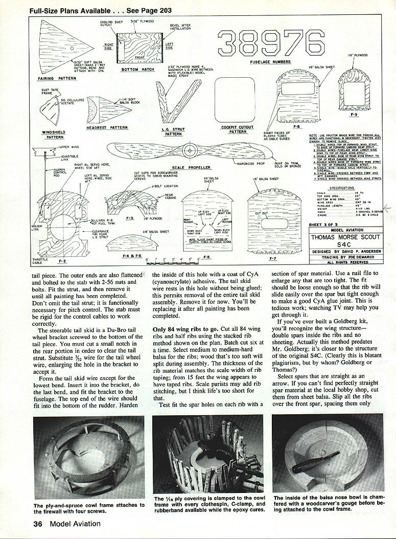
Thomas Morse Scout S4C
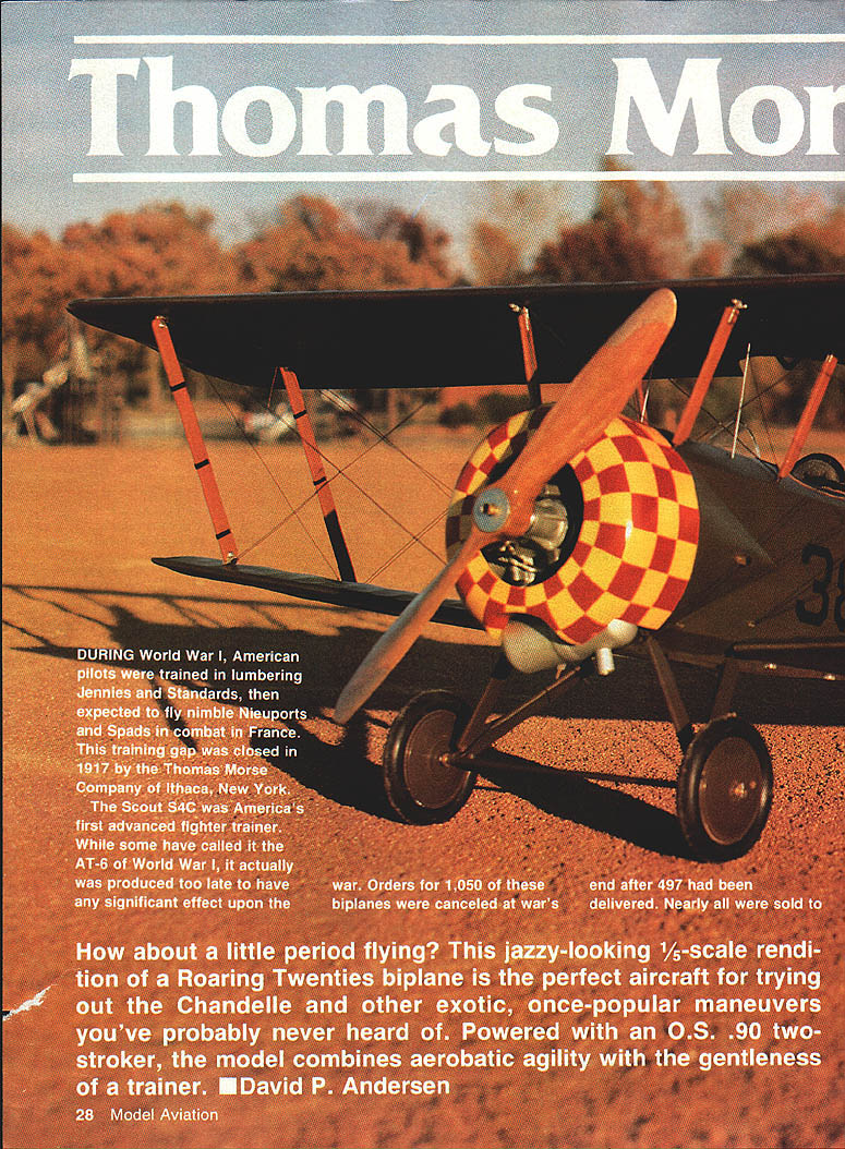
During World War I, American pilots were trained in lumbering Jennies and Standards, then expected to fly nimble Nieuports and Spads in combat in France. This training gap was closed in 1917 by the Thomas Morse Company of Ithaca, New York.
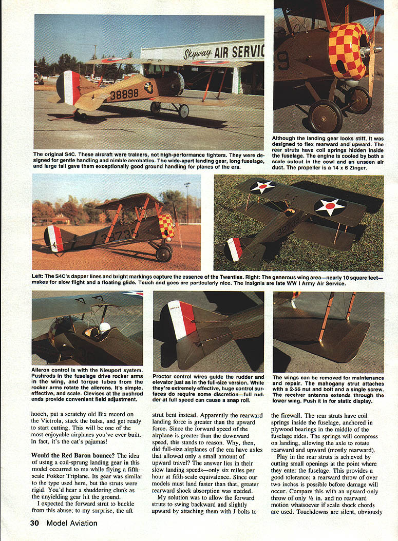
The Scout S4C was America's first advanced fighter trainer. While sometimes compared to the AT-6 of World War II, it was produced too late to have any significant effect on the war. Orders for 1,050 biplanes were canceled at war's end after 497 had been delivered. Nearly all were sold to the public, and the S4C was widely used throughout the 1920s both as a private airplane and in flying schools. Many of the apparent Sopwiths in movies such as Wings and Hell's Angels were actually Tommies, just as AT-6s were used to simulate Japanese Zeros in later films.
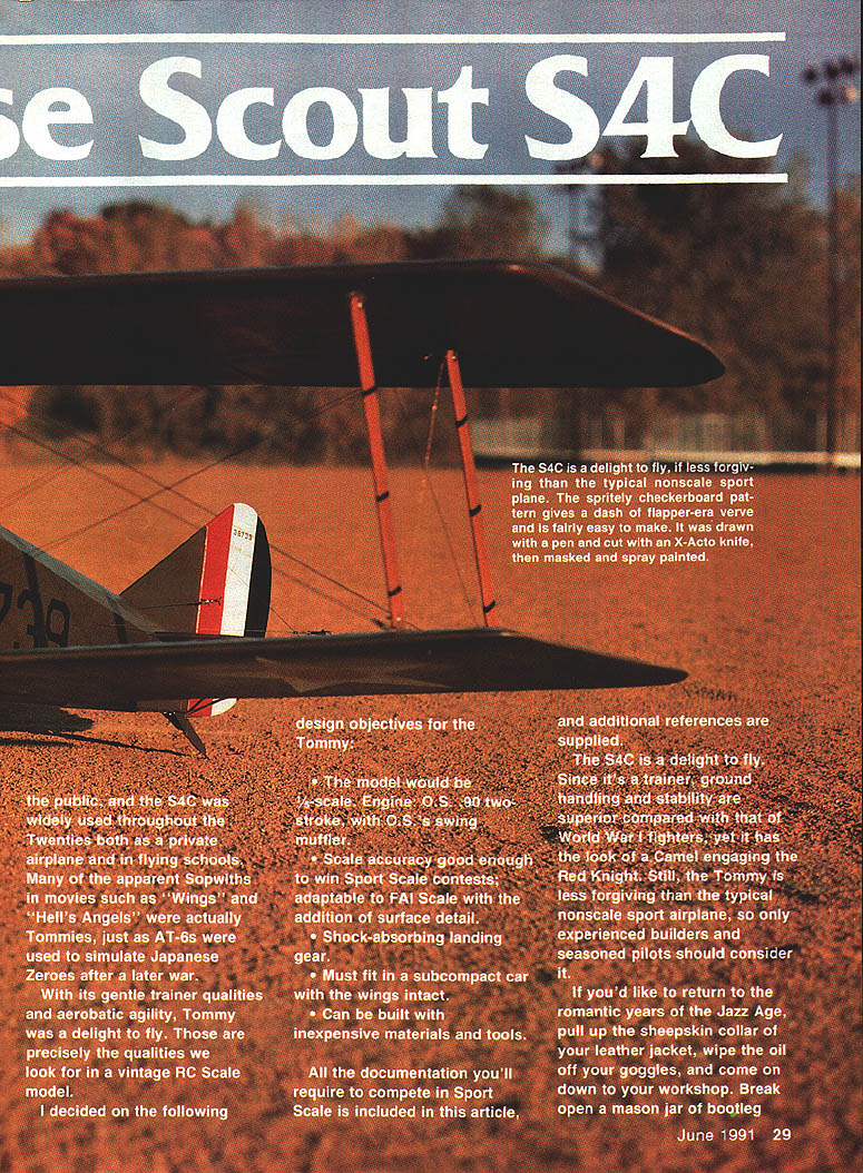
With gentle trainer qualities combined with aerobatic agility, the S4C (Tommy) was a delight to fly. Those are precisely the qualities sought in a vintage RC scale model.
David P. Anderson
Design objectives for the model
- Scale: 1/5-scale.
- Power: O.S. .90 two-stroke engine with O.S. swing muffler.
- Scale accuracy: good enough for Sport Scale contests; adaptable to FAI Scale with added surface detail.
- Landing gear: shock-absorbing.
- Transport: must fit in a subcompact car with wings intact.
- Construction: achievable with inexpensive materials and ordinary tools.
- Documentation: include all paperwork required for Sport Scale competition.
Construction overview
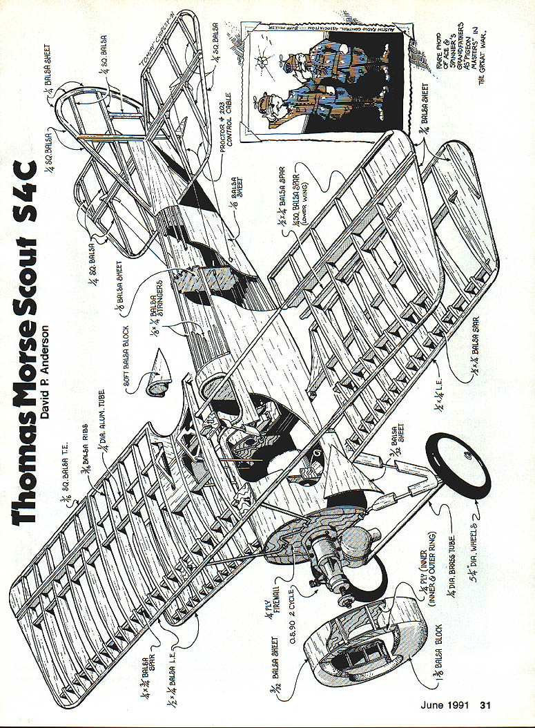
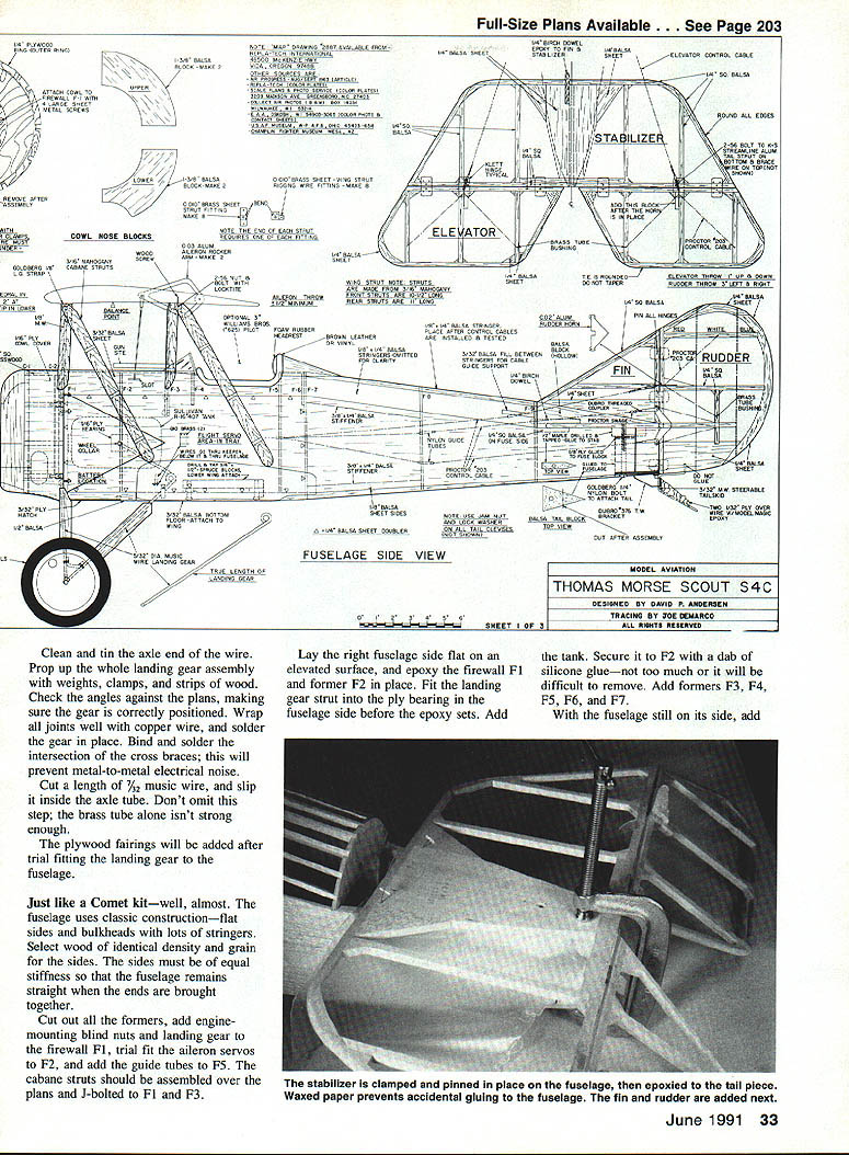
The model uses classic construction: flat fuselage sides and bulkheads with stringers. Select wood of identical density and grain for both sides so the fuselage remains straight when assembled.
Cut out formers, add engine-mounting blind nuts and landing-gear fittings to firewall F1, trial-fit the aileron servos to F2, and install guide tubes to F5. Assemble cabane struts over the plans and J-bolt them to F1 and F3.
Lay the right fuselage side flat on an elevated surface, epoxy firewall F1 and former F2 in place, and fit the landing-gear strut into the plywood bearing before the epoxy sets. Add the fuel tank and secure it to F2 with a dab of silicone glue for removable service. Add formers F3–F7. Repeat for the other side, inserting the rear leg into its bearing and piling on weight to hold sides in place while glue cures. Epoxy a large gusset of hard balsa or spruce at the firewall joints—this is a high-stress area.
Add the remaining formers and the triangular tail block, then add stringers after glue cures.
Landing gear (design and construction)
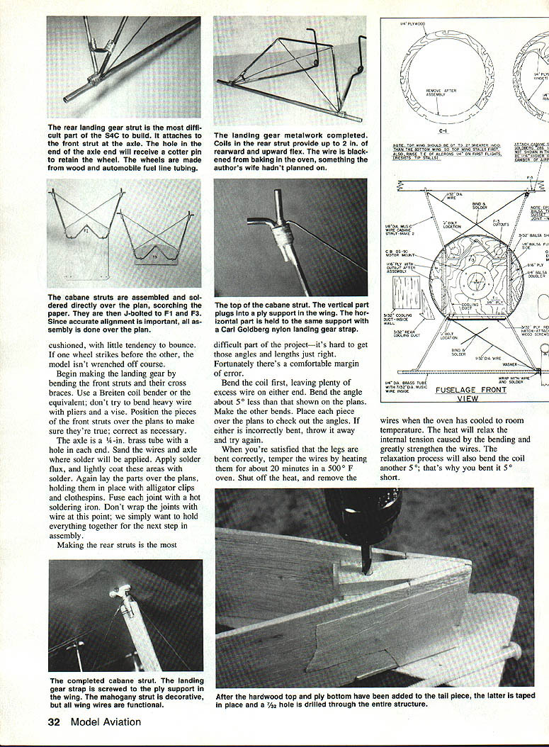
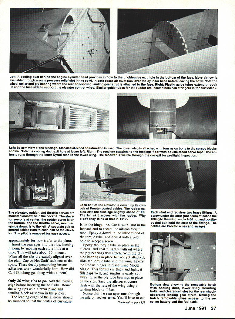
The rear landing-gear strut is the most difficult part of the build. The model uses coil-sprung rear struts that provide both rearward and upward axle travel (up to about 2 in.) for shock absorption. The forward struts are attached to the firewall with J-bolts so they can swing rearward and slightly upward on landing. Springs are anchored in plywood bearings on the middle fuselage sides; small openings where the rear struts enter the fuselage provide play and tolerance.
Key points and procedure:
- Bend front struts and crossbraces with a Breitenbach (Breiten) coil bender or equivalent. Do not try to bend heavy wire with pliers or a vise.
- Position pieces over the plans to ensure true alignment. File or sand axle hole ends as required.
- Axle: use 1/4-in. brass tube. Clean and tin the axle ends and the wire where solder will be applied. Slip a length of 7/32-in. music wire inside the axle tube for strength.
- Apply solder flux, lightly coat solder areas, hold parts over plans with clips, and fuse joints with a hot soldering iron. Do not wrap joints with wire at this stage—hold everything in place for final soldering.
- Bend and assemble the rear struts, including the coil. Bend the coil slightly under the final angle (about 5° less), then temper wires: heat in a 500°F oven for ~20 minutes, then cool to relax internal stresses (expect the coil to open up ~5°).
- Clean and tin axle ends and mount the whole assembly on props. Check alignment against plans. Wrap joints well with copper wire and solder in place; bind and solder intersections of cross braces to prevent metal-to-metal electrical noise.
- Add wheel collars where the rear struts project from the fuselage to prevent pull-out. The axle ends receive cotter pins to retain the wheels.
- Fit the cabane strut and landing-gear strap assembly; screw the strap to plywood supports at the wing. The mahogany strut is decorative; the flying wires are functional.
Wheels: make wheels from turned balsa with automobile fuel-line tubing for tires; bake/harden in the oven if desired. This yields cushioned wheels with little tendency to bounce.
Wings and spars
- Cut 84 wing ribs and half-ribs using the stacked-rib method shown on the plan; batch-cut six at a time. Use medium to medium-hard balsa to avoid splitting.
- Test-fit spar holes on each rib with a section of spar material; make holes loose enough for the rib to slide easily yet tight enough for a good CyA glue joint.
- Wing structure: double spars inside ribs and no sheeting on the main wing panels—closer to the original S4C structure.
- Slip all ribs over the front spar, space as shown on the plan, then slip in the rear spar and square the ribs. Build the wing flat on the board, add cap strips and doublers required.
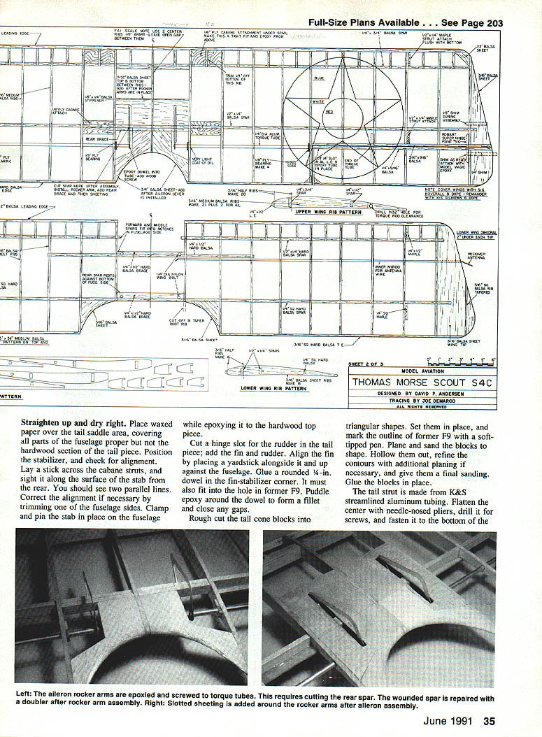
- Insert rear spar through aileron rocker arms where indicated.
- Round wing tips with a razor plane and sanding block; outer rib is cut down to half thickness at the forward spar.
- The leading edges of ailerons should be rounded so that the center of curvature is on the hinge line. Cut a 1/4-in. slot in the inboard end to accept the aileron torque tube, epoxy a dowel in the tube's inboard end and drill a pilot hole for a screw. Epoxy the torque tube in place and coat lightly with oil where ply bearings will attach. Use Robart hinges set with Model Magic epoxy.
Ailerons, elevator, rudder and controls
- Aileron control uses pushrods and a Proctor-type control system. Pushrods run in the fuselage to drive rocker arms. Proctor control wires guide the rudder.
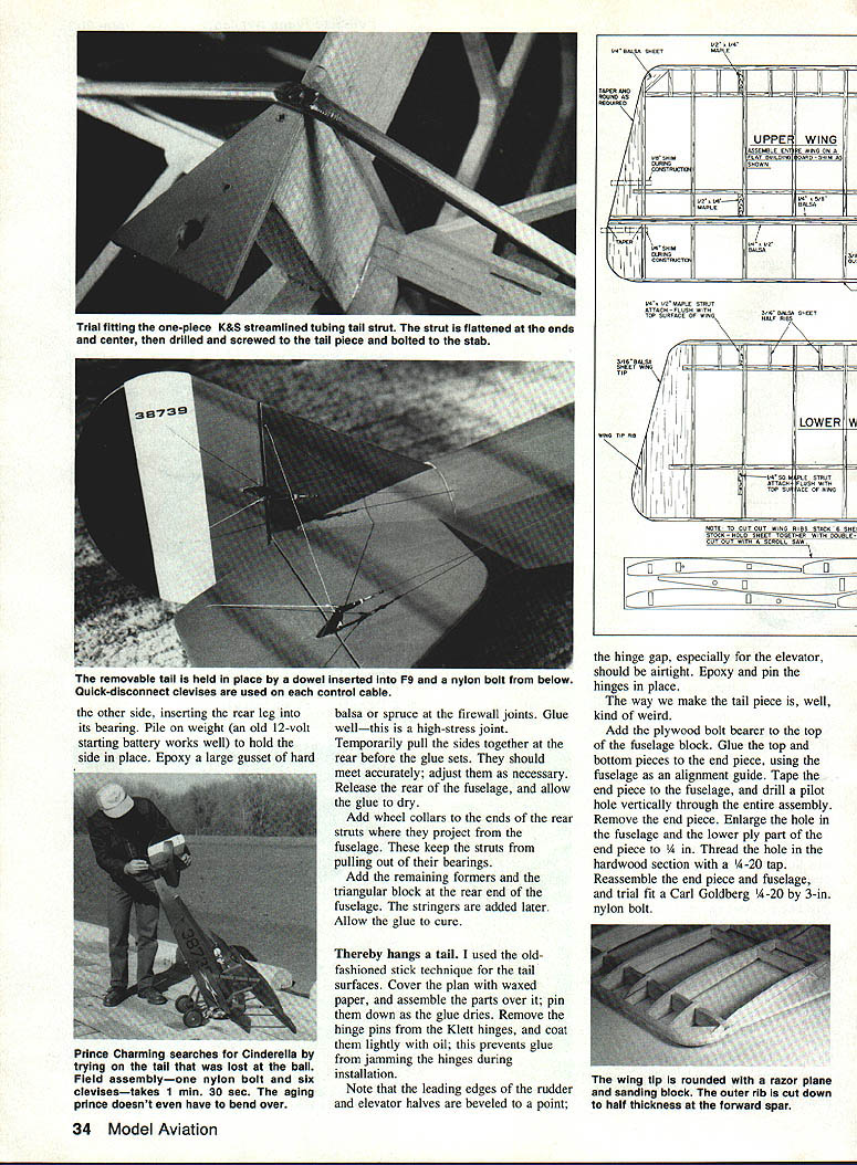
- Each half of the elevator is driven by its own pair of Proctor control cables. The rudder cables exit the fuselage slightly ahead of former F9; the tail skid moves with the rudder.
- Control cables attach to Du-Bro threaded couplers with Proctor swages: loop cable through coupler and swage, then crimp the swage.
- Use metal clevises at the tail end (tolerant of disassembly) secured with a 2-56 nut and lock washer. Use nylon clevises at the servo end for easy adjustment.
- Elevator, rudder, and throttle servos are mounted crosswise in a servo tray in the cockpit: elevator servo centered, rudder servo on the bottom, throttle servo mounted upside down to the left. Glue balsa blocks with 1/8-in. ply faces to the fuselage sides and screw servos to the ply faces.
- Install a separate pair of control cables to each half of the elevator. Provide a plastic tube guide through former F8 for the elevator cables; glue guide with a fillet of baking soda and CyA, and cut tubes flush with the fuselage.
Tail assembly
- Build tail surfaces using stick technique over waxed paper, pinning parts while glue dries. Remove Klett hinge pins, coat lightly with oil to prevent glue jamming.
- Leading edges of rudder and elevator halves are beveled to a point; hinge gaps (especially elevator) should be airtight. Epoxy and pin hinges in place.
- Add plywood bolt bearer to top of fuselage tail block. Glue top and bottom pieces to the end piece using the fuselage as alignment guide. Tape the end piece to the fuselage and drill a pilot hole vertically through the assembly. Enlarge the hole in the fuselage and lower ply part of the end piece to 1/4 in. Thread hardwood section with a 1/4-20 tap. Trial-fit a 1/4-20 x 3-in. nylon bolt (Carl Goldberg style).
- Glue a rounded 1/4-in. dowel in the fin-stabilizer corner; it must also fit into the hole in former F9. Puddle epoxy around dowel to form fillet and fill gaps.
- Rough-cut tail cone blocks to triangular shapes, mark former F9 outline, plane and sand to shape, hollow as needed and glue in place.
Cowl, nose bowl, and cooling
- Cowl frame: two rings of 1/4-in. ply and 1/4-in. hardwood stringers. Rear frame screws to firewall with four screws accessible with a long screwdriver even when engine and muffler are installed. Install 1/4-in. ply spacers behind the rear ring to allow cabane and landing-gear attachments and to permit cowl trimming.
- Build the cowl frame first; align with a triangle before slow-set epoxy hardens. Wrap a single length of 1/16-in. ply strip around the frame with slow-setting epoxy and clamp with rubber bands, C-clamps, or clothespins. Trim ply and cut lower frame for muffler clearance as shown on plan. Fit cowl to firewall and drill screw holes; bolt in place and trim for neat scale appearance.
- Nose bowl: cut from four pieces of 1/8-in. balsa sheet (if unavailable, glue two 3/16-in sheets together and thin). Chamfer inside before gluing to cowl frame. Round outside with a razor and plane using a paper template. Cut pressure relief slot in lower right of cowl to allow glow-plug starter access.
- Cooling: propwash enters front of cowl and builds compressed air that escapes via leaks around muffler, pressure-relief slot, and a cooling duct behind the engine cylinder. Two sheet-balsa baffles close to the cylinder help force airflow over the head. The cooling duct (behind firewall) is made from two sheets of 1/32-in. balsa. Cooling is usually better with the cowl installed.
Finishing and covering
- Cover wings with Sig Koverall attached with nitrate dope. Cover bottom first; add a small fillet of white glue alongside each rib so fabric won't pull away from undercambered ribs.
- Sheeted parts: lightweight silkspan; open fuselage and tail: heavyweight silkspan.
- Dope schedule: three coats—nitrate base coat, clear butyrate coat (sand to remove fuzz), and top color coat. Prime metal parts (axles, tail strut) with nitrate dope (nitrate adheres to metal; butyrate bonds to nitrate).
- Paint details and roundels as required. Example khaki brown mix: 1 quart Sig chocolate brown + 1 pint Sig olive drab, thinned 1:1. For cowl checkerboard: several coats of butyrate sanding sealer, spray Cub yellow, cover with liquid masking film, cut checker pattern, spray Fokker red for alternate squares, remove mask and spray two wet coats of clear butyrate for gloss.
- Paint tail strut and tail skid separately. Assembled tail should weigh no more than about five ounces.
Scale detail tips (Sport Scale)
- Paint upper wing brackets and tail nylon bolt head for detail.
- Recess bolt heads on lower wing; fill with modeling clay and paint the clay for appearance—bolt can be removed later by pushing screwdriver through clay.
- Use two ribs in the center of the upper wing and remove covering between them to appear as two wings bolted together.
- Add a removable scale Pitot tube on the interplane strut (AMA rules require removability for flight).
- Add a scale machine gun and sight from balsa and aluminum tubing; sight from soda straw.
- Use a quarter-scale Williams Bros. pilot on a ply base (pilot removable to access servos). Sport Scale requires a pilot for flight scoring but not for static display—decide based on contest rules.
- Make wheels from wood and automobile fuel-line tubing to scale diameter (3-1/4 in. suggested) for extra craftsmanship points.
Rigging and brace wires
- Use Proctor No. 203 stranded wire or equivalent for brace wires. To prevent unraveling, treat with a drop of Zap or Hot Stuff before cutting.
- All brace wires are pulled only tight enough to take up slack; avoid excessive tension. Adjustable turnbuckles are not used—too expensive and not scale.
- Lift and landing wires: lift wires and landing wires are double; cross wires at cabane and interplane struts are single. Bind cross points with a loop of thread and add a drop of CyA to prevent metal-to-metal electrical noise.
- Rear pair of lift wires runs through the fuselage fitting, through the fuselage and to the opposite wing strut fitting. Forward lift wires loop around the landing gear strut at the firewall. Landing wires loop around cabane struts.
Powerplant options and mounting notes
- The basic recommendation is the O.S. .90 two-stroke as used on the prototype model.
- Four-stroke substitution: possible to use a large four-stroke (O.S. 1.20 Surpass or Enya .120), but requires upright mounting, more airflow, and additional 2 in. spacing from prop to firewall. Suggested modification: add a second firewall 2 in. behind F1, cutout in F1 for cylinder head clearance, use two separate wires for front cabane struts, and block all cowl airflow except over cylinder. Angle muffler straight down between F1 and the new firewall. Glow-plug access will be under the top wing—use a remote glow-plug jack.
- O.S. 1.08 two-stroke may also fit in cowl in some configurations.
- Always break in and tune the engine on the ground with the exact prop, muffler, and fuel to be used in flight. Install the engine in the model without altering the tuned settings.
Flying characteristics and technique
- The S4C has a long fuselage, large tail and generous wing area (nearly 10 sq. ft. scale area equivalent), yielding good ground handling, slow flight, floating glide and nice touchdowns.
- Crosswind ground handling is poor: crosswinds tend to pass under upwind wingtips and roll the airplane downwind. Always take off and land directly into wind, holding wings level with ailerons and steering with rudder.
- Aileron response is sluggish; elevators are sensitive; rudder is very powerful. To turn sharply, bank with ailerons and use rudder to kick the tail around—practice at altitude.
- Full rudder at full speed can cause a snap roll of the lower wing—use caution.
- Throttle has little effect on airspeed; flying speed remains slow regardless of throttle—power mainly affects climb rate. Trim to climb at full throttle; approach field at about one-quarter throttle and control rate of descent with throttle rather than elevator.
- For landing, use a bit of up elevator at about 10 ft altitude, keep wings level, and touch down gently. Three-point landings are particularly attractive in this type.
- Steam-era maneuvers: loops and rolls are graceful; try Chandelles (climbing 180° turns with wings level, coordinated with rudder and opposite aileron). Period names (vrille for spin, virage for circle) add charm during contest flying.
Final assembly and notes
- After final construction, install engine and muffler, balance the model as required, and complete rigging and trim adjustments.
- Check and recheck all fittings, bolts, and use Loctite 242 threadlocker where vibration may loosen nuts—allow 24 hours to set before flying. Apply Loctite sparingly and follow product instructions.
- Use metal clevises and secure them to prevent rotation; use nylon clevises at servos for ease of adjustment.
- For static display, removable items such as antenna should be pushed into place; ensure they are removed prior to flight.
- A reliable engine is essential—if the engine quits, the model does not glide far. Ensure thorough ground testing.
Tips and cautions
- Use a Breiten coil bender for wire shaping; do not try to bend heavy wire with pliers.
- Temper bent wires in an oven to relieve internal stresses and strengthen them.
- When soldering landing-gear joints, bind first and then solder; check alignment over plans.
- Keep finish lightweight; minimize dope/paint coats to preserve flying weight.
- Practice crosswind takeoffs and landings on a sport plane before trying them on the S4C model.
David P. Anderson
Transcribed from original scans by AI. Minor OCR errors may remain.

