
Those Torturous Canopies
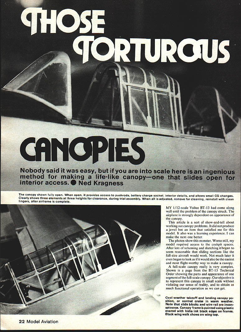
My 1/12-scale Vultee BT-13 had come along well until the problem of the canopy struck. The airplane is strongly dependent on the appearance of the canopy. This article is a show-and-tell about working out canopy problems. It did not produce a jewel but an item that satisfied me for this model and it was a useful learning experience. I can make the next one better.
The photos show this monster. Worse still, my model required access to the cockpit spaces. After lots of scheming and sketching it began to seem reasonable that sliding sections like the full‑size aircraft would work. Not much later it also began to look as if sliding sections would be the easiest and most flight‑worthy way to make a canopy.
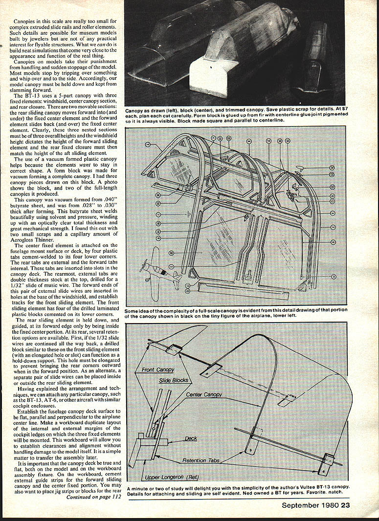
A full‑scale canopy is very complex. Shown is (in original source) a page from the BT‑13 Technical Order showing the parts and appearance of one segment of the full‑scale canopy. Our objective is to represent that canopy in small scale without violating our sense of reality and to obtain as much functional operation as we can.
Vacuum forming
Vacuum‑formed plastic canopies help because the elements want to stay the correct shape. A form block was made and a complete canopy vacuum formed. Three canopy pieces were drawn from the block; the photos show the block and two full‑length canopies produced.
The canopy was vacuum formed from .040" butyrate sheet; the formed thickness was about .028"–.030". Butyrate welds beautifully using solvent and pressure, producing an optically clear joint with good mechanical strength. I found that two small scraps with a capillary amount of Aerogloss Thinner made good welds.
Canopy arrangement and attachment
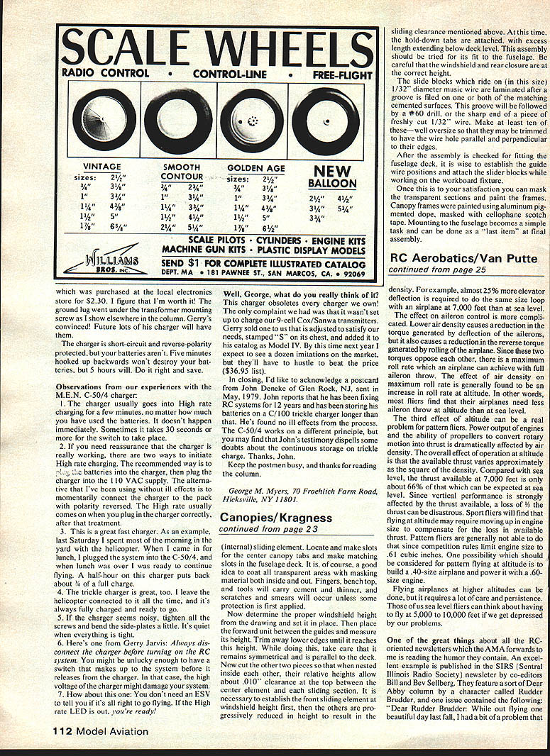
The BT‑13 uses a 5‑part canopy with three fixed elements and two movable sections:
- Fixed: windshield, center canopy section, rear closure.
- Movable: forward sliding element (slides back over the center section) and rear sliding element (moves forward under the center section).
These three nested sections must be of three overall heights. The windshield height dictates the height of the forward sliding element; the rear fixed closure must match the height of the aft sliding element.
Attachment details used on this model:
- The center fixed element is mounted on the fuselage canopy deck surface by four plastic tabs cement‑welded at its lower corners. The rear tabs are external; the forward tabs are internal and are inserted into slots in the canopy deck.
- The rearmost external tabs are of double‑thickness stock and are drilled to take 1/32" music wire to act as guide/track.
- The forward ends of that pair of external slide wires are inserted into holes at the base of the windshield to establish tracks for the front sliding element.
- The front sliding element has four laminated plastic blocks drilled and cemented to its lower corners; these blocks ride on the guide wires.
- The rear sliding element is held down and guided at its forward edge by being inside the fixed center portion. At its rear, several retention options are available:
- Continue the 1/32" slide wires all the way back and fit a drilled block with an elongated hole/slot to function as a hold‑down support. The slot must be elongated to prevent pulling the rear corners outward when the canopy is in the forward position.
- As an alternative, use a separate pair of slide wires placed inside or outside the rear sliding element.
Canopies in this scale are usually too small for complex extruded slide rails and roller elements. Such details are possible for museum models built by jewelers but are not of practical interest for flyable structures. Instead, neat simulations can be built that closely approximate the appearance and function of the real thing.
Canopy assemblies on models take punishment from handling and sudden stoppage. Most models stop by tripping over something and whip over and to the side; accordingly, the model canopy must be held down and kept from slamming forward.
Workboard assembly (fixture)
Before attaching anything to the model:
- Establish the fuselage canopy deck surface so it is flat, parallel and perpendicular to the airplane centerline.
- Make a workboard duplicate layout of the internal and external margins and cockpit ledges where the three fixed elements will be mounted. The workboard serves as an assembly fixture and allows establishment of clearances, alignment and handling without damage to the model itself. It is a simple matter to transfer the assembly to the model later.
- It is important that the canopy deck be truly flat on both the model and the workboard.
On the workboard:
- Cement external guide strips for the forward sliding canopy and the center fixed portion.
- Place jig strips or blocks for the rear sliding element if desired.
- Locate and make slots for the center canopy tabs and make matching slots in the fuselage deck.
- Mask all transparent areas both inside and out. Fingers, the bench top and tools will carry cement and thinner, and scratches and smears will occur unless protection is applied first.
Sizing, trimming and clearances
- Determine the proper windshield height from the drawing and set it in place.
- Place the forward sliding unit between the guides and measure its height. Trim lower edges until it reaches the correct height, taking care to keep it symmetrical and parallel to the deck.
- Cut the other two pieces so that, when nested inside each other, their relative heights allow about .010" clearance at the top between elements and each sliding section. Establish the front sliding element at the windshield height first; then progressively reduce the others to provide the sliding clearance.
- Attach the hold‑down tabs with excess length extending below deck level. Try the complete assembly for fit to the fuselage and confirm the windshield and rear closure heights are correct.
Slide blocks and guide wires
- The slide blocks which ride on 1/32" diameter music wire are laminated after a groove is filed on one or both of the matching cemented surfaces. This groove is followed by a #60 drill or the sharp end of a fresh‑cut 1/32" wire.
- Make at least ten of these blocks—oversize so they may be trimmed to get the wire hole parallel and perpendicular to their edges.
- After the assembly is checked on the workboard, establish the guide wire positions and attach the slider blocks while still working on the fixture.
Notes on hold‑down:
- If using drilled blocks with an elongated hole, the slot prevents the rear corners from being forced outward when the rear sliding element is moved forward.
- Alternatively, separate internal or external slide wires for the rear sliding element can be used.
Painting and final mounting
Once satisfied with fit and movement:
- Mask the transparent sections (inside and out) and paint the frames. I painted canopy frames using aluminum‑pigmented dope and masked with cellophane (Scotch) tape.
- Mounting to the fuselage becomes a simple task and can be done as a last item at final assembly.
Tips and reminders:
- Work on the canopy assembly off the model as much as possible; the workboard prevents accidental damage.
- Keep the canopy deck and workboard perfectly flat—this is critical to alignment.
- Use care when trimming to maintain symmetry and parallelism.
- Protect clear areas from cement, thinner and scratches with masking before any cementing or painting.
Transcribed from original scans by AI. Minor OCR errors may remain.

