
Three-Line Control Handle
John Brownlee
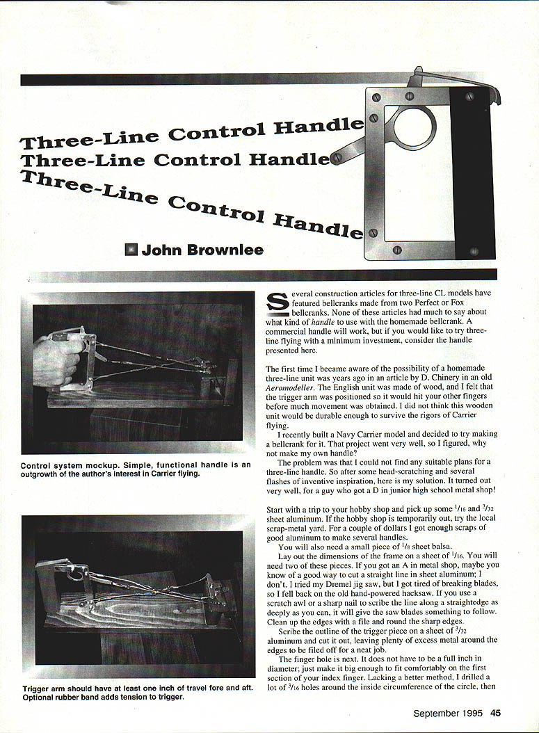
Several construction articles for three-line CL models have featured bellcranks made from two Perfect or Fox bellcranks. None of these articles said much about what kind of handle to use with a homemade bellcrank. A commercial handle will work, but if you would like to try three-line flying with a minimum investment, consider the handle presented here.
I first became aware of the possibility of a homemade three-line unit years ago in an article by D. Chinery in an old Aeromodeller. The English unit was made of wood, and I felt the trigger arm was positioned so it would hit your other fingers before much movement was obtained. I did not think that wooden unit would be durable enough to survive the rigors of carrier flying.
After building a Navy Carrier model and a bellcrank for it, I decided to make my own handle. I couldn't find suitable plans, so after some head-scratching I developed the following simple design. It turned out very well for a fellow who got a D in junior high school metal shop!
Materials
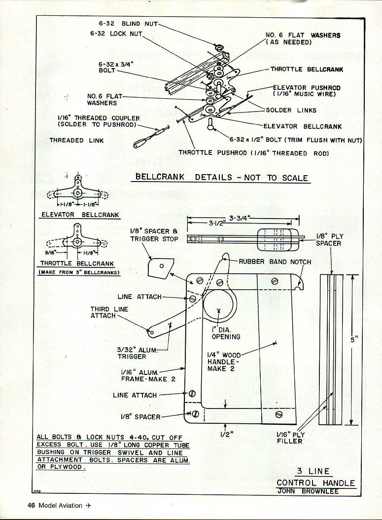
- 1/16" sheet aluminum — make two frame pieces
- 3/32" sheet aluminum — trigger piece
- Small piece of hard 1/8" plywood (spacer between back frames)
- Optional 1/16" plywood shim to close up space between 1/4" side pieces
- Three 1/8" pieces of brass or copper tubing (bushings)
- 4-40 bolts and lock nuts for all fastenings (cut off excess bolt lengths)
- 1/8" sheet balsa (for wooden handle)
- Paint/varnish and fuelproof finish
- Rubber bands (optional), plus notches for them
Note: Do not use Lite Ply for spacers — it is too soft.
Tools and general tips
- Scribe outlines with a scratch awl or sharp nail along a straightedge before cutting.
- A hacksaw works well for cutting aluminum sheet if power tools are unavailable; file and round edges afterward.
- Drill and countersink holes where indicated.
- Drill several 3/16" holes to rough out the finger hole, then file the remaining web away and clean up with a rat-tail file.
- Use three short tubing bushings around the bolts at the line-attachment points and the trigger-swivel bolt.
Construction
- Lay out the frame dimensions on 1/16" sheet aluminum and cut two identical frame pieces. Clean up and round all edges with a file.
- Scribe the outline of the trigger piece on 3/32" aluminum and cut it out, leaving generous metal for final filing and fitting.
- Make the finger hole large enough to fit comfortably on the first section of your index finger — it need not be a full inch in diameter. Drill many 3/16" holes around the inside circumference, remove the web, and finish the hole with a rat-tail file.
- Mark and drill the holes for the 4-40 bolts that hold the frame and trigger together.
- Prepare spacers: a piece of hard 1/8" plywood serves as a spacer between the back two aluminum frames. If needed, use a 1/16" plywood shim to close up the space between the 1/4" side pieces. Make the trigger-stop spacers for the front corners of the frame from 1/8" aluminum, two pieces of 1/16" aluminum, or hard 1/8" plywood.
- Install three 1/8" brass/copper tubing pieces as bushings around the line-attachment bolts and the trigger swivel bolt.
Assembly and fitting
- Assemble the unit using 4-40 bolts and lock nuts. Cut off excess bolt lengths after assembly.
- File and fit the trigger-stop spacer so the front of the finger hole just touches the back of the frame. The line-attachment hole in the trigger arm may come within 1/16" of the frame front.
- Ensure the trigger arm has at least 1" of travel fore and aft; more travel is desirable. An optional rubber-band adds tension to the trigger — add notches on the handle if you want this feature.
- Paint or varnish the wooden handle and apply a fuelproof finish.
Installation and final setup
- Attach the cables using approved wrapping methods.
- The elevator cables and the third-line cable must be the same length both at the handle and at the model's wingtip. Proper setup can yield smooth throttling and very precise landings.
Notes and specifications
- All bolts and lock nuts: 4-40. Cut off excess bolt length.
- Use 1/8" tubing bushings on the trigger swivel and line-attachment bolts.
- Spacers: aluminum or hard plywood.
May you have smooth throttling and 100-point landings.
Transcribed from original scans by AI. Minor OCR errors may remain.

