
Tigercat
Dennis Norman
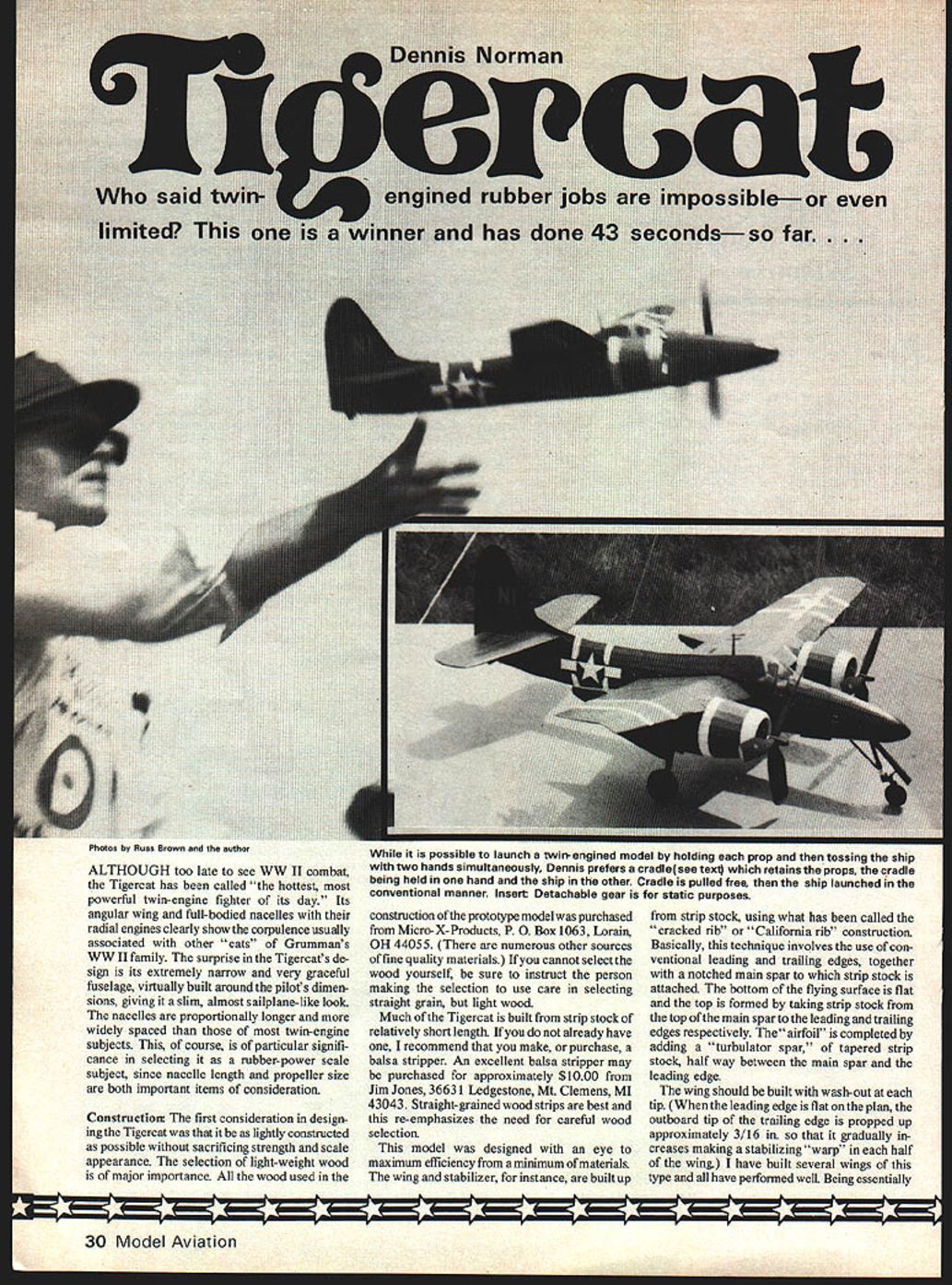
Although too late to see WWII combat, the Tigercat has been called "the hottest, most powerful twin-engine fighter of its day." Its angular wing, full-bodied nacelles and radial engines clearly show the corpulence usually associated with other "cats" of Grumman's WWII family. The surprise in the Tigercat's design is its extremely narrow, very graceful fuselage—virtually built around the pilot's dimensions—giving a slim, almost sailplane-like look. The nacelles are proportionally longer and more widely spaced than those of most twin-engine subjects. This is of particular significance in selecting a rubber-powered scale subject, since nacelle length and propeller size are both important considerations.
Construction
The first consideration in designing the Tigercat was to make it as lightly constructed as possible without sacrificing strength or scale appearance. Selection of lightweight, straight-grained wood is of major importance. Much of the Tigercat is built from strip stock of relatively short length.
Recommended suppliers and tools:
- Micro-X-Products, P.O. Box 1063, Lorain, OH 44055 (prototype materials).
- Balsa stripper (recommended if you do not already have one). An example source: Jim Jones, 36631 Ledgestone, Mt. Clemens, MI 48043 (approx. $10 at the time referenced).
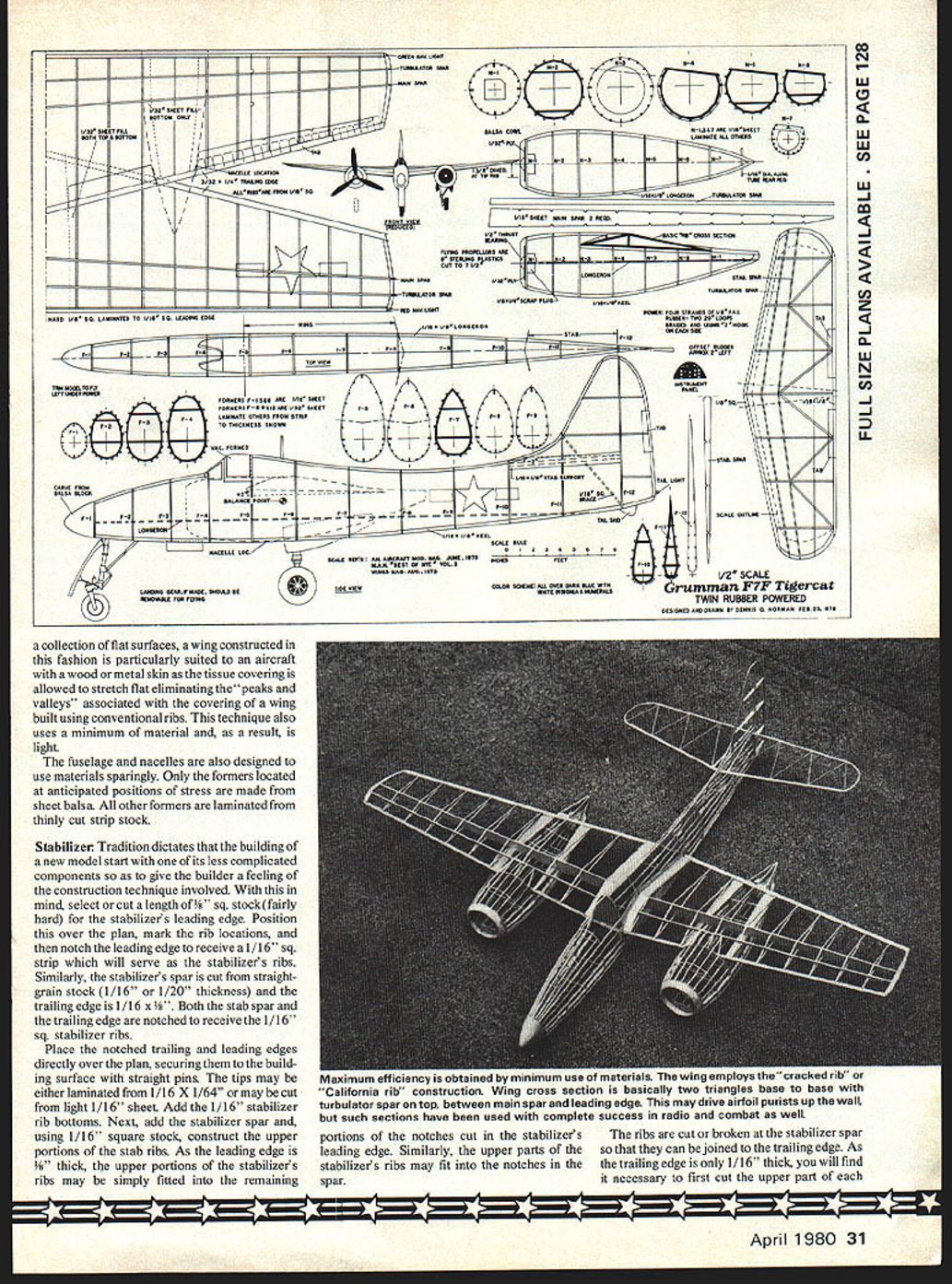
The model was designed with an eye for maximum efficiency using a minimum of materials. The wing and stabilizer, for instance, are built up from strip stock using the "cracked rib" or "California rib" construction. This technique uses conventional leading and trailing edges together with a notched main spar to which strip stock is attached. The bottom of the flying surface is flat; the top is formed by taking strip stock from the top of the main spar to the leading and trailing edges respectively. The airfoil is completed by adding a turbulator spar—tapered strip stock—halfway between the main spar and the leading edge.
The wing should be built with washout at each tip: when the leading edge is flat on the plan, the outboard tip of the trailing edge is propped up approximately 3/16 in., gradually increasing to create a stabilizing warp in each half of the wing. Wings constructed in this fashion perform well. Being essentially a collection of flat surfaces, this construction is particularly suited to aircraft with wood or metal skins; tissue covering may be shrunk flat, eliminating the "peaks and valleys" associated with conventional ribbed wings. This technique also uses minimal material and yields a light structure.
The fuselage and nacelles are likewise designed to conserve materials. Only the formers located at anticipated positions of stress are cut from sheet balsa; other formers are laminated from thinly cut strip stock.
Stabilizer
Tradition dictates beginning with a less complicated component to learn the construction technique. For the stabilizer:
- Select or cut a length of 1/8" square fairly hard, straight-grained stock for the stabilizer's leading edge.
- Position it over the plan and mark rib locations. Notch the leading edge to receive 1/16" square strips that will serve as the stabilizer ribs.
- Cut the stabilizer spar from straight-grain stock (1/16" or 1/20" thickness). Use 1/16" x 5/8" for the trailing edge. Notch the spar and trailing edge to receive the 1/16" square ribs.
- Secure the notched trailing and leading edges over the plan with straight pins. Make tips from 1/16" sheet or laminate from 1/16" x 1/64" strips.
- Add 1/16" stabilizer rib bottoms, then the stabilizer spar. Construct the upper portions of the ribs from 1/16" square stock; fit them into the remaining notches in the leading edge and spar.
- Cut or break the ribs at the stabilizer spar so they join the trailing edge. Because the trailing edge is only 1/16" thick, cut the upper part of each stabilizer rib to a length equal to the distance from the stabilizer spar to the trailing edge. To avoid a bumpy trailing edge, remove each upper rib part, then cut the underside of the rear part to an acute angle so it has greater surface contact with the 1/16" square bottom portion of the rib. The upper surface of the ribs should blend smoothly with the trailing edge, requiring little sanding.
- Add the stabilizer's turbulator spar of hard 1/32" square or 1/16" square strip stock. When dry, round the leading edge and tips and taper the trailing edge and turbulator spar.
Wing
Following the stabilizer technique:
- Select pieces of 3/32" x 1/4" strip stock and notch them for the wing's trailing edge as shown on the plan.
- Construct the leading edge using butt-joined 1/16" square pieces for greater strength; notch the 1/16" portion to receive the flat bottom pieces of the wing ribs.
- Cut the main spar from 1/16" sheet and notch as shown on the plan.
- Position and secure the notched leading and trailing edges on the plan. Fit 1/16" square bottom rib portions into the notches to join leading and trailing edges.
- Place a 3/16" thick strip at the outer tip of the trailing edge before permanently joining pieces—this creates built-in washout for stability.
- Glue the main spar over the plan to the lower portions of each wing rib. Fashion the upper rib portions from 1/16" square similarly to the stabilizer.
- Glue the turbulator spar in place. Add the wing tip (1/16" sheet or laminated). Break the wing tip so it follows the contour from trailing edge to the upper main spar, then to the turbulator spar and down the leading edge.
- Round the leading edge and wing tips and taper the trailing edge.
Fuselage
This design uses minimal materials with maximum effect. Only formers F-1, F-5, F-6 (cut from 1/16" sheet) and F-8, F-9, F-12 (cut from 1/32" sheet) are solid sheet wood; these are located where strength is required. Each former is notched to receive longerons and stringers and keys the location of the fuselage's longitudinal structural members. Remaining formers are laminated to form supports for stringers where high structural strength is not required. The fuselage and fin portion of the vertical stabilizer are built as one unit.
To keep the fuselage shape true, build it on a jig:
- Use a piece of 3/8" masonite and draw the fuselage profile. Cut away the locations of the formers.
- Fasten the bottom 1/16" x 3/16" keel to the masonite jig using pieces of masking tape after cutting approximately 1/16" deep notches to receive the hollow formers.
- Position solid formers (F-1, F-5, F-6, F-8, F-9, F-12) on the bottom keel and add the top keel. Glue formers in place, squaring them with a small plastic triangle.
Hollow formers:
- Construct undersized built-up formers by cutting 1/64" strips from 1/16" sheet. Join four strips and bend them into the shape on the plan to create a hollow former. Cement with cyanoacrylic glue and complete each hollow with 1/16" square cross braces.
- Fit hollow formers into the keel structure and cement with white glue or model cement due to minimal surface contact.
Longerons and stringers:
- Fit 1/16" x 3/16" side longerons, notched to fit. Longerons fit snugly in solid formers but only touch hollow formers. Use cyanoacrylic glue to cement longerons to solid formers; use white glue or model airplane cement for hollow formers.
- Add stringers by fitting into notches in solid formers and gluing to hollow formers. All but the uppermost and lowermost stringers should be in place before removing the fuselage frame from the jig; add the final stringers after removal.
Vertical tail and fin:
- As indicated by former F-12, the vertical tail is of tapered thickness. Cut the two horizontal ribs in the fin from scrap 1/32" or 1/16" sheet and taper from the width at F-12 down to the thickness at the fin's leading edge.
- The contour of the upper fuselage immediately behind the cockpit should be rounded; fill between formers F-5 and F-7 with tapering pieces of 1/16" sheet, sand and round to approximate the full-size aircraft. The rudder (movable part) is built separately.
Nacelles
Construct nacelle formers and longerons using the same techniques as the fuselage. Assemble on a masonite jig to hold them true during assembly. Mirror the plan formers to make the left nacelle. The nacelles are proportionally longer and more widely spaced, which favors this model as a rubber-powered scale subject.
Component Assembly
- Join wing halves to the fuselage center so the leading edge of each wing half is joined in front of former F-5. The main spars meet just behind F-6, and the trailing edges join at F-8. Deeply notch F-8 to permit the trailing edges to pass through it and remove portions of fuselage stringers where they block the main spar.
- The dihedral on the model is substantial—approximately 1 3/8 in. at each tip rib—and the approximate dihedral angle is indicated on formers F-5 and F-6.
- Once the wing halves are positioned so the leading and trailing edges and main spar meet, join the halves with epoxy. Before permanently attaching the wing to the fuselage, check that it has approximately two degrees of incidence (use the side longeron as a reference).
- Join the wing permanently to the fuselage with epoxy, using scrap balsa to fill any gaps between the wing and nearby supporting fuselage formers.
- Fill the area between the root rib and the fuselage with 1/32" sheet for strength and as a base for the tissue covering. Install 1/32" x 3/32" strip pieces following the airfoil shape adjacent to the wing root for additional strength and tissue attachment.
Nacelle installation:
- Join each nacelle to the wing at the positions shown on the plan. Align the angled tops of formers N-4, N-5, N-6 and N-7 with the underside of the wing. Epoxy the trailing edge to N-7 and join the leading edge to N-3 as shown.
- Fill the area between each nacelle and the underside of the nearest wing rib with 1/32" sheet. There is no need to sheet the top surfaces except the portion between N-3 and the turbulator spar.
Landing Gear
Landing gear is optional. Flying Aces' rules permit subjects with retractable gear to be flown "wheels up," eliminating weight and drag. For static display, detachable gear may be desirable. Suggested technique:
- Make gear removable using a "plug-in" type: install small receptacles of 1/16" aluminum tubing at points where the main gear members meet the fuselage or nacelles.
- Fashion landing gear components with 1/32" wire pins that slide into the aluminum tube receptacles.
- Build the receptacles before covering if you intend to use landing gear.
Covering and Coloring
With wing and fuselage assembled and 1/32" sheet fill added at key points (wing roots, etc.), you have strengthened stress areas and provided anchor points for tissue covering.
Color schemes:
- Almost all Tigercats were overall dark navy blue. The prototype described here is dark navy blue; the original aircraft prototype was silver.
- Other F7Fs have been seen in yellow, silver, red, white and black trim. This model uses red, white and blue trim, similar to a Marine Corps F7F at El Toro in 1946.
Finishing:
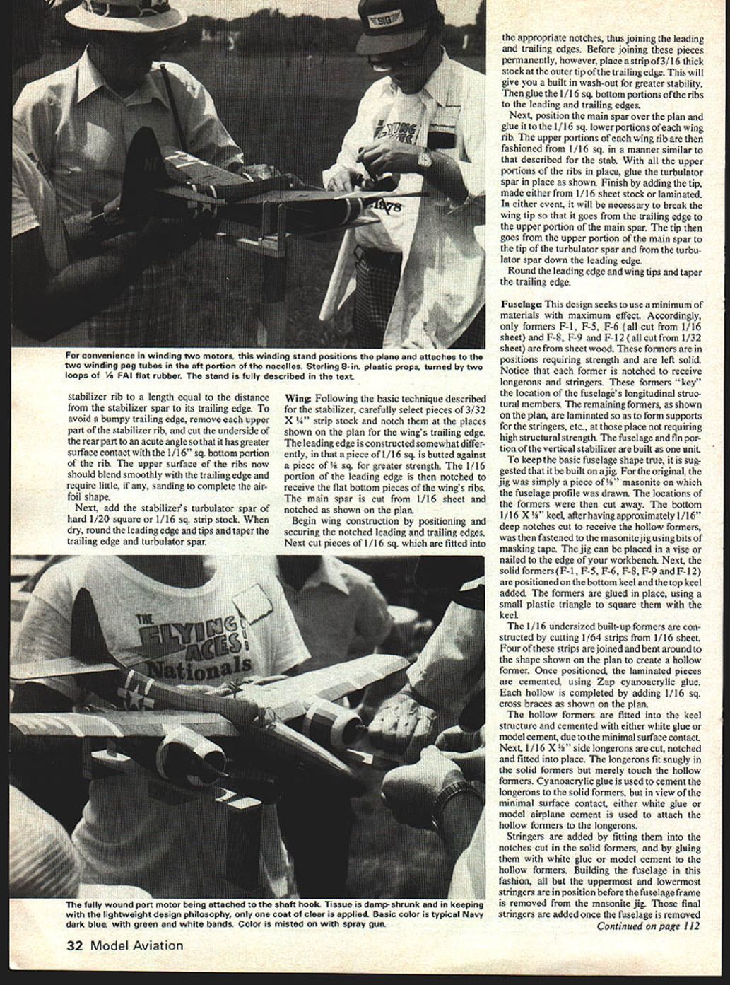
- After shrinking the tissue, apply only a single coat of dope in keeping with the lightweight philosophy.
- Because no rubber motor passes through the fuselage, you may install a completely detailed cockpit and full pilot figure if desired. A simple pilot bust (carved from styrofoam) is an acceptable lightweight option.
- References for cockpit detail: Model Airplane News book "Best of the F7F, Vol. 3" and the 1/72 Monogram plastic kit for scale details.
Propellers
- The author used 8" Sterling plastic propellers cut to 7-1/4". Static three-bladed props were also made using 7" Slick Streak props epoxied at appropriate angles. The model will probably fly on three-bladed props, but this has not yet been tried.
Motors and Winding
- Best results to date were obtained using two 20" loops of 1/8" FAI flat rubber, braided to better distribute the weight of the unwound motors.
- Rear motor pegs are short lengths of 1/16" aluminum tubing positioned at the rear of each nacelle. Because the motors are longer than the distance between the rear motor peg and the propeller hook, use propeller hooks bent to give an apparent "Z" when viewed from behind; this inhibits a long motor from climbing the propeller shaft and binding the mechanism.
Winding stooge and launching:
- Construct a winding stooge: a large H-shaped structure with pieces of 1/16" plywood or tongue depressor portions attached to fit on either side of the rear motor peg. Pass a 1/32" wire through these "tongues" and through the rear motor peg to hold the unit stable while winding. Fasten the H-shaped stooge base to a stake driven into the ground.
- For launching, a cradle is useful: a piece of 1 x 2 pine stock with two notched uprights that fit over the propeller hubs and keep the motors from unwinding. Hold the model at F-8 and F-9 with one hand and the cradle with the other, pull the cradle away from the propellers and release the model.
Trimming and Performance
- The author built the model to fly left under power and added approximately two degrees left side-thrust and two degrees down-thrust to each propeller. The rudder was offset approximately two degrees to the left.
- Finished weight (without propellers or motors): 11-1/2 ounces. Balance point is approximately 1-1/2" ahead of former F-6.
- Flight characteristics: remarkably stable with a steep, rapid climb under power. Initial stabilizer design produced a lifting effect that caused a steep dive from altitude, limiting flight time to about 30 seconds. Building a thicker, lifting stabilizer solved climb, but required countering its nose-down glide effect.
- Adjustments: changing elevator angle of attack (more "up" elevator) countered lifting tendencies and improved the glide. Best flight time since adjustments: 44 seconds (Wright-Patterson AFB on September 24, 1978). The design should be capable of one-minute flights with further tinkering and favorable lift (thermal) conditions.
Transcribed from original scans by AI. Minor OCR errors may remain.

