

Tiny Sailplane: The AR-25
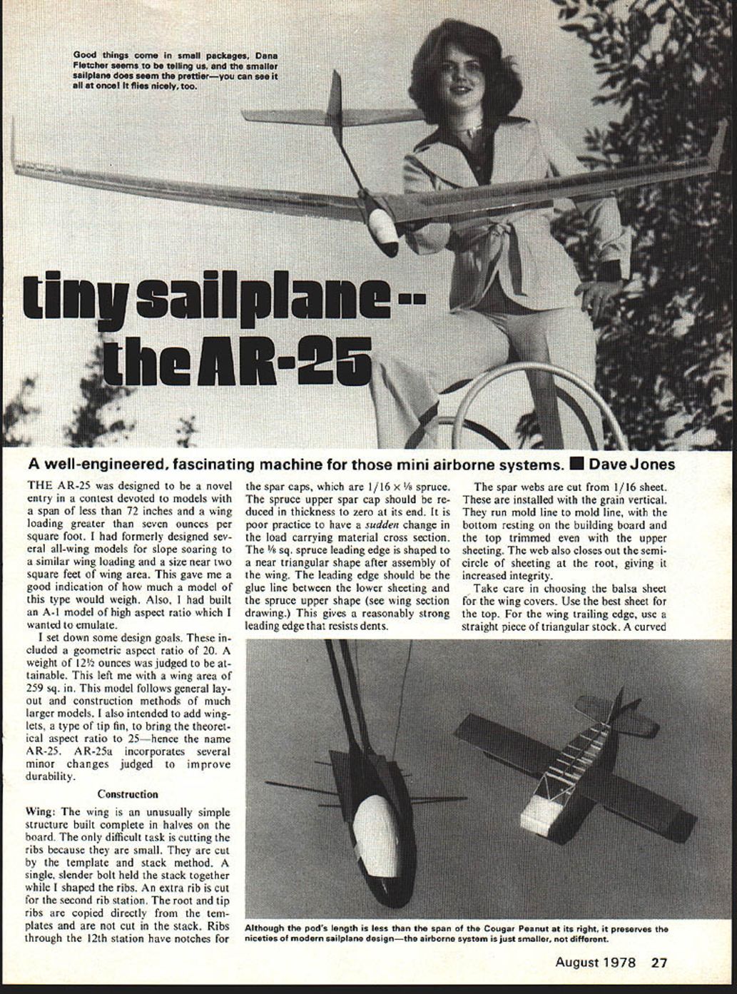
A well-engineered, fascinating machine for those mini airborne systems. Dave Jones
THE AR-25 was designed to be a novel entry in a contest devoted to models with a span of less than 72 inches and a wing loading greater than seven ounces per square foot. I had formerly designed several all-wing models for slope soaring to a similar wing loading and a size near two square feet of wing area. This gave me a good indication of how much a model of this type would weigh. Also, I had built an A-1 model of high aspect ratio which I wanted to emulate.
I set down some design goals. These included a geometric aspect ratio of 20. A weight of 12½ ounces was judged to be attainable. This left me with a wing area of 259 sq. in. This model follows general layout and construction methods of much larger models. I also intended to add winglets, a type of tip fin, to bring the theoretical aspect ratio to 25—hence the name AR-25. AR-25a incorporates several minor changes judged to improve durability.
Construction
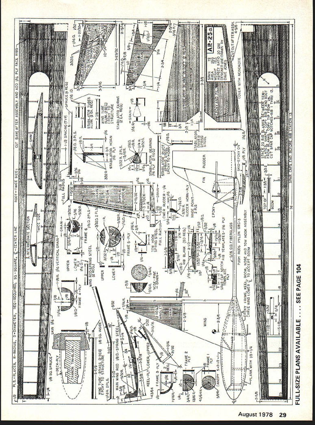
Wing: The wing is an unusually simple structure built complete in halves on the board. The only difficult task is cutting the ribs because they are small. They are cut by the template and stack method. A single, slender bolt held the stack together while I shaped the ribs. An extra rib is cut for the second rib station. The root and tip ribs are copied directly from the templates and are not cut in the stack. Ribs through the 12th station have notches for the spar caps, which are 1/16 x 1/8 spruce. The spruce upper spar cap should be reduced in thickness to zero at its end. It is poor practice to have a sudden change in the load carrying material cross section. The 1/8 sq. spruce leading edge is shaped to a near triangular shape after assembly of the wing. The leading edge should be the glue line between the lower sheeting and the spruce upper shape (see wing section drawing). This gives a reasonably strong leading edge that resists dents.
The spar webs are cut from 1/16 sheet. These are installed with the grain vertical. They run mold line to mold line, with the bottom resting on the building board and the top trimmed even with the upper sheeting. The web also closes out the semicircle of sheeting at the root, giving it increased integrity.
Take care in choosing the balsa sheet for the wing covers. Use the best sheet for the top. For the wing trailing edge, use a straight piece of triangular stock. A curved one can sometimes be straightened by sanding on one side to help relieve the stresses in the wood. The wing ribs may be capped, but it is an extra job I don't deem necessary on this model. The wing under load will act just like a full-size fiberglass sailplane, and bow in a graceful curve.
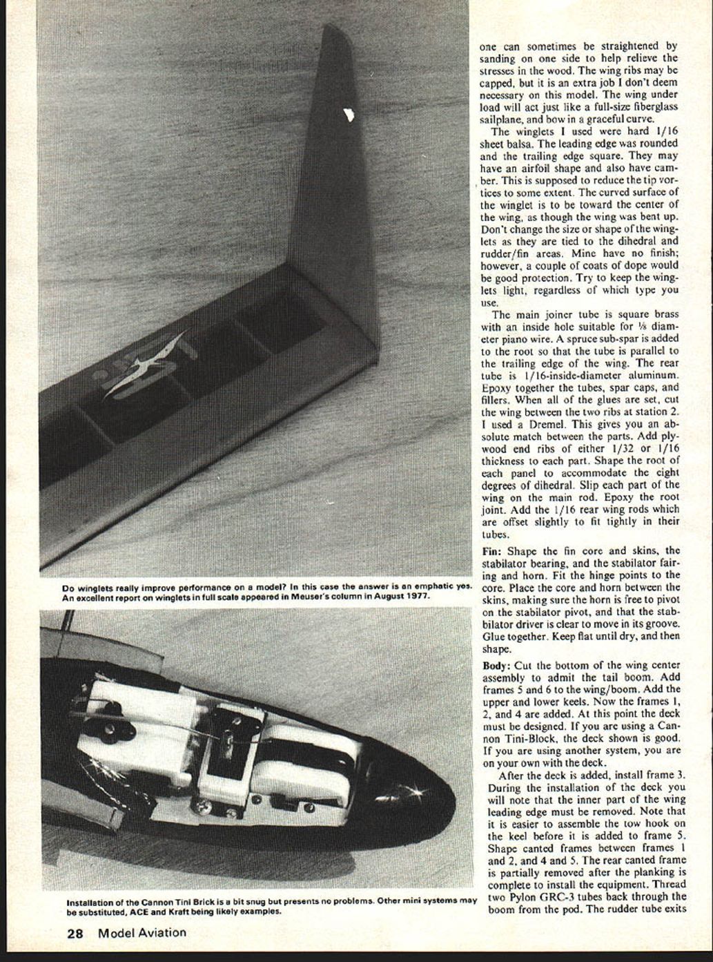
The winglets I used were hard 1/16 sheet balsa. The leading edge was rounded and the trailing edge square. They may have an airfoil shape and also have camber. This is supposed to reduce the tip vortices to some extent. The curved surface of the winglet is to be toward the center of the wing, as though the wing was bent up. Don't change the size or shape of the winglets as they are tied to the dihedral and rudder/fin areas. Mine have no finish; however, a couple of coats of dope would be good protection. Try to keep the winglets light, regardless of which type you use.
The main joiner tube is square brass with an inside hole suitable for 1/8 diameter piano wire. A spruce sub-spar is added to the root so that the tube is parallel to the trailing edge of the wing. The rear tube is 1/16-inside-diameter aluminum. Epoxy together the tubes, spar caps, and fillers. When all of the glues are set, cut the wing between the two ribs at station 2. I used a Dremel. This gives you an absolute match between the parts. Add plywood end ribs of either 1/32 or 1/16 thickness to each part. Shape the root of each panel to accommodate the eight degrees of dihedral. Slip each part of the wing on the main rod. Epoxy the root joint. Add the 1/16 rear wing rods which are offset slightly to fit tightly in their tubes.
Fin: Shape the fin core and skins, the stabilator bearing, and the stabilator fairing and horn. Fit the hinge points to the core. Place the core and horn between the skins, making sure the horn is free to pivot on the stabilator pivot, and that the stabilator driver is clear to move in its groove. Glue together. Keep flat until dry, and then shape.
Body: Cut the bottom of the wing center assembly to admit the tail boom. Add frames 5 and 6 to the wing/boom. Add the upper and lower keels. Now the frames 1, 2, and 4 are added. At this point the deck must be designed. If you are using a Cannon Tini-Block, the deck shown is good. If you are using another system, you are on your own with the deck.
After the deck is added, install frame 3. During the installation of the deck you will note that the inner part of the wing leading edge must be removed. Note that it is easier to assemble the tow hook on the keel before it is added to frame 5. Shape canted frames between frames 1 and 2, and 4 and 5. The rear canted frame is partially removed after the planking is complete to install the equipment. Thread two Pylon GRC-3 tubes back through the boom from the pod. The rudder tube exits the pod.
Winglets really improve the performance of the model. In my case the answer is an emphatic yes. Although the pod is shorter than the span, the design preserves the niceties of a modern sailplane—the same airborne system, just smaller. Different pieces can sometimes be straightened by sanding the sides to help relieve stresses. The wood wing ribs may be capped; this is an extra job I don't deem necessary. The model wing under load will act like a full-size fiberglass sailplane and will bow in a graceful curve.
Use hard 1/16-inch sheet balsa for the winglets. The leading edge is rounded and the trailing edge square. They may be given an airfoil shape and camber to reduce tip vortices to some extent. Curve the surface of the winglet toward the center of the wing even though the wing is bent up. Don't change the size or shape; winglets are tied into the dihedral/rudder/fin areas. Mine have no finish; however, a couple coats of dope would give good protection. Try to keep the winglets light regardless of type.
Use the main joiner tube of square brass with an inside hole suitable for 5/32-inch diameter piano wire. A spruce sub-spar is added at the root. The tube runs parallel to the trailing edge; the rear tube is 1/16-inch inside-diameter aluminum. Epoxy the tubes together, add the spar caps, fillers and glues, then set and cut the wing between two ribs at station 2. Using a Dremel gives an absolute match between parts. Add plywood end ribs, either 1/32- or 1/16-inch thickness. Shape the root panel to accommodate eight degrees dihedral. Slip the wing main rod into the part and epoxy the root joint. Add 1/16-inch rear wing rods, offset slightly to fit tightly into the tubes. the boom on the left side ahead of the stabilator horn. Epoxy a clevis on the stabilator cable and attach the clevis to the horn. Fit the fin to the boom. When you are sure everything is working and free, epoxy the fin in place. Now plank the pod.
Add the nose block and sand the planking to the round cross section. Shape a soft block for the canopy/hatch. Hollow it to fit your equipment. A skid has been fitted to the bottom of the pod, but it is prone to instant removal during crosswind landings. With this in mind, a plastic skid (Scuff Guard) or several layers of masking tape provide all the protection needed. If you are adept with fiberglass, the pod can be covered with, or made from, light fiberglass and resin. This will ensure an extremely strong model.
Control Surface
The wood for the stabilator must be light and reasonably rigid. Very little work is done to it, so spend your time selecting a good piece of wood. A flat plate section is used for simplicity. It is true that it will stall at low angles of attack, but by using a square trailing edge, the wake is thin. This allows very small deflections to give control response. Some Sharp trailing edge control surfaces can be deflected several degrees before they impinge on high energy air. Cut the stabilator from soft 1/8" sheet, and inset the 1/16" inside-diameter aluminum tube into the balsa at the correct locations. Match the stabilator horn. The rudder is made in three pieces, a blade, a driver and a horn. Assemble and attach to the fin. I used hinge points.
Finish: The prototype wing and stabilator were covered with transparent orange on the top, and black on the bottom. The pod was covered with black as was the fin. A good paint finish would be easier on the pod and boom. The canopy was white. These coverings were Super Monokote.
Equipment Installation: Care must be exercised in fitting the radio in the model. The large canopy helps make it easy. My two-channel Cannon Tini-Block fit in with all the stock wire, plugs and switch. Yes, the switch was mounted under the canopy next to the battery on the right side. The antenna was routed out of the pod on the right side between frames 5 and 6 through a small plastic tube. It was supported by the top of the fin.
The plug between the switch and the receiver should be above the deck for ease of recharging. I placed mine on the right side adjacent to the receiver. The lead runs from the switch aft under the servo and receiver and up the right side to the top of the deck. The plug is placed just in front of the canted frame and beside the receiver. The lead from the receiver comes out and through the deck at the center and forward of the receiver. It runs from the center around the right corner of the receiver aft to the switch lead. The servo/receiver leads pass to the left of the receiver, and the plugs are behind the receiver.
Flying: The center of gravity shown is satisfactory for slope flying, but you may want it farther aft for thermal flying. Hand launches to 30 feet are possible by putting your fingers behind the wing center section. High-starts with light rubber, or hand tows, are easily accomplished. When you are familiar with the characteristics of the model, add the winglets. The improvement in flight should be evident with the winglets in place. The prototype glide and turn characteristics are both improved. Although the winglets may look vulnerable, they aren't prone to flying/landing damage. However, they are vulnerable during transportation and storage.
Conclusion: I hope you enjoy your version as much as I enjoy mine. I feel this configuration could be scaled to twice this size or more with a gradual increase in performance due to scale factor. Let me hear from you about your model. Write Dave Jones, 5621 Michelle Drive, Torrance, CA 90503.
Transcribed from original scans by AI. Minor OCR errors may remain.

