

Tomahawk II
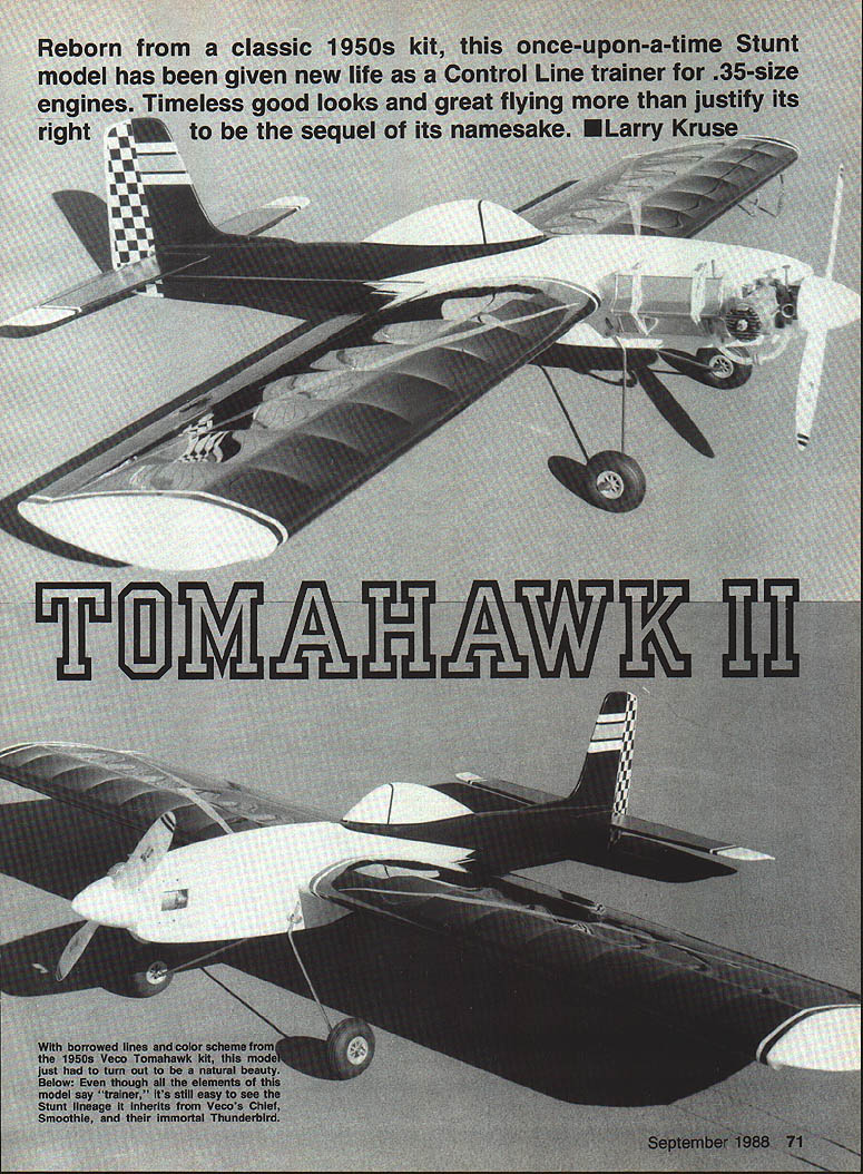
Reborn from a classic 1950s kit, this once-upon-a-time stunt model has been given new life as a control-line trainer for .35-size engines. Timeless good looks and great flying more than justify its right to be the sequel of its namesake. — Larry Kruse
A look-alike of the Tomahawk profile control-line trainer kitted by Veco over three decades ago, the Tomahawk II was designed to be somewhat larger and to fly even better than its namesake. Although it mimics the appearance of the Veco original, this latter-day version is in no way intended to replicate the earlier model. Even without wing flaps, stretching the wingspan and lengthening the tail moment a tad has resulted in a docile, gentle-flying trainer that is both smooth and responsive on the lines.
Back in the 1950s, the Tomahawk made its mark as part of a Veco series of control-line ships with Indian names such as the Brave, Warrior, and Chief. The company even carried the theme over into free-flight offerings with the Navajo, Scout, and the immortal Sioux. The original Tomahawk was a good-looking profile ship designed for engines from .19–.35 cu in. It likely competed with popular models of the day such as the Ringmaster, Mustang, and Yak. When Veco went out of business, the Tomahawk disappeared from the modeling scene until this updated version.
My interest in the Tomahawk was reawakened by a couple of faded Polaroids and an advertisement from Model Airplane News, circa 1954. The ad showed a paint scheme of solid colors, stripes, checkerboard squares, and arrows. Despite the motley decoration, the design remains pleasing by today’s standards. According to the ad, the original Tomahawk had a 40 in. wingspan and many prefabricated parts. While materials cost more today, by scrounging from a scrapbox and recycling hardware, an airplane can be produced for a modest outlay.
Construction
If this is your first attempt at scratch-building, pre-kit the entire airplane before beginning actual assembly. Pre-kitting means cutting out sheet parts, laying aside needed strip wood, cutting and bending wire to length, and locating necessary hardware such as control horns, hinges, bellcrank, bolts, etc. Since cutting out wing ribs individually can be tedious, make up an appropriate number of rib blanks and stack-saw the entire batch in one operation.
Wing
- Pin down the trailing edge and bottom spar and glue the ribs to their respective locations. Prop up the trailing edge along its full length with small scraps of balsa so it remains parallel to the building board during the operation.
- When the glue is dry, turn the wing over and repeat the procedure on the opposite spar.
- Attach the remaining trailing-edge piece and the leading edge. The leading edge can be positioned by cutting eight 10-1/4 in. pieces of 1/4-in. sq. spruce (hardwood or Popsicle sticks will also work). Place the Popsicle sticks behind the 1/4-in. sq. spars at equal intervals, loop rubber bands over the protruding ends and around the leading edge, and double up the rubber bands as needed to keep the leading edge snug in the rib notches.
- Use Super Jet adhesive (or similar) in each rib/leading edge joint to lock the joint into position.
- Install the bellcrank assembly, leadouts, and pushrod, then sheet the center section. To help the sheeting conform to rib curvature, dampen each piece on the outside as necessary.
- Attach the trailing-edge cap strip and the wing tips. Thoroughly sand the completed wing structure.
- Don’t forget to add 1 oz. of lead as a balance weight in the outboard wing.
Use an appropriate fillet of epoxy or filler to smooth any joints before final sanding. If covering with silkspan or silk, plan on additional coats of dope to fill the grain (see Covering and finishing).
Tail surfaces
- Cut the tail surfaces from medium-weight 3/16-in. balsa.
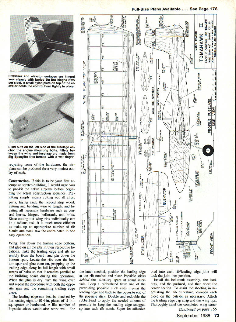
- Chamfer the rudder and glue it to the fin with a 1/2-in. offset to the right as viewed from the rear.
- Slot the stabilizer and elevators to accept four Du-Bro nylon hinges, or use over/under cloth hinges if preferred.
- Drill the elevators to accept the wire joiner, epoxy it in place, and reinforce with fiberglass tape.
- Test-fit the elevator assembly to the stabilizer, ensuring there are no misaligned hinges that cause binding or bowing. If it moves freely, epoxy the hinges into their slots, taking care that epoxy does not ooze into the hinge joints and render them immobile.
- Carefully sand the stabilizer and elevator, rounding all edges, then set aside with the wing for final assembly.
Fuselage
- Laminate the fuselage blank using a 4 x 3 in. piece of even-grained 1/2-in. balsa for the main body and a 2 x 2 in. piece for the nose top and canopy section.
- Cut out the fuselage outline and saw the slots for the maple engine bearers, the wing opening, and the stabilizer slot.
- Pay particular attention to alignment of the engine, wing, and stabilizer to maintain zero-degree incidence between the power source and the flying surfaces.
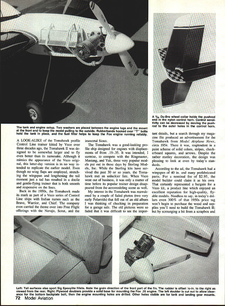
- Engine bearers are cut from 3/8 x 3/4-in. maple stock; nose doublers are 1/8-in. Sig Lite-Ply. Use the engine bearers as a guide to cut out the right side of the engine mount area; relieve the left side as required so the engine seats flat against the right-side doubler.
- Drill engine-mount holes using the selected engine as a template. Drill holes for the landing gear and its retaining clips. Bushing the landing-gear mounting hole with a short piece of brass tubing will prevent wear from repeated impacts.
- Sand the fuselage carefully, tapering the plywood doubler to fair into the balsa fuselage. Taper the rear of the fuselage from just behind the wing down to a 3/16-in. width at the tail so the rudder fits smoothly.
Final assembly
- Slide the wing into its mounting hole in the fuselage and epoxy it in place. Make final alignments before the epoxy sets.
- After the wing/fuselage joint cures, glue the fixed flaps into position and sand them to fair smoothly into the main wing panels.
- Align the stabilizer squarely and glue it into position.
- Glue the rudder and sub-rudder in place. Glue the rudder firmly to survive occasional nose-overs on rough landings; consider epoxying a strip of fiberglass to the sub-rudder to prevent wear from ground scraping.
- Connect the pushrod to the elevator using a large Sig nylon control horn. Tape or pin the elevator at neutral before installing the pushrod to ensure equal up and down movement. The bellcrank must be set at neutral as well.
- Test-fit landing gear and retainer, and bolt the engine into position.
- Locate the position of the fuel-tank brackets or straps, making sure the tank pick-up tube is in line with the engine venturi. Even a 1/8 in. misalignment can cause the engine to run unevenly upright vs. inverted.
- Balance the model at the point shown on the plans; add or remove weight as necessary to achieve proper balance. Use small commercially available stick-on weights and glue them permanently in place when happy with the balance.
Covering and finishing
Since the Tomahawk II is a profile trainer, you probably won't want to lavish a great deal of time on finishing. Most profile ships look smart in simple color schemes that are easy to repair. The prototype was finished in a busy 1954-ad style, but simpler schemes work equally well.
- Form fillets of Sig Epoxolite around wing, stabilizer, and rudder where attached to the fuselage. Epoxolite can be smoothed with a wet finger; a Popsicle stick makes a good spatula. Wipe off excess before it sets.
- Prepare all balsa surfaces for finish by filling with a talcum-powder/clear-dope mixture or a commercial balsa filler such as Aerogloss.
- After filling and sanding smooth, apply three coats of clear dope to fuselage, rudder, and stabilizer.
- For the wing: if using Monokote, brush on two coats of Balsarite to promote adhesion. If using silkspan or silk, brush on at least four coats of dope (often five to seven additional coats required) to help the material adhere and fill the grain.
- Consider spraying the wing panels with a light sanding sealer before covering. For bright solid colors, use a coat or two of white dope as a primer. Apply color in several thin coats to avoid runs and sags. Colored dope adds weight quickly, so use only as much as necessary for an even appearance.
- When finish is fully dry, hook up controls and reinstall landing gear and engine in preparation for flight.
Flying
The Tomahawk II makes an excellent first or second airplane. With a classic Fox .35 (or similar) mounted in the nose, it is a slow, stable flier with extremely smooth responses—giving a novice plenty of time to react.
Preparation for the first flight:
- Pull-test the flying lines and ensure they are not kinked.
- Check elevator throw and confirm that up movement equals down; adjust the handle if necessary.
- Fill the tank and start the engine.
Needle-valve setup: aim for a setting that allows the engine to four-cycle when the plane is level and then break into a two-cycle mode as the nose either drops or rises. Adjust until the engine is just barely dropping from a fast four-cycle to two cycles during altitude changes. With the engine running on the ground, tip the nose up and flip the plane over on its back to ensure the engine runs evenly in all attitudes. Be extremely conscious of propeller position during these checks.
For launch: have a helper launch the plane from a three-point position on the ground. Let it roll out about a quarter-lap before giving a little up on the control handle. The plane should break ground smoothly and remain at the commanded altitude. Fly a couple of level laps to familiarize yourself with the model before beginning any vertical maneuvers.
My hope is this fresh rendition of an old favorite will introduce today’s beginning modelers to the delights of control-line flight, just as the early Tomahawk did more than 30 years ago.
Plans
Full-size plans available. See page 178.
Transcribed from original scans by AI. Minor OCR errors may remain.

