
Tomy Toy Power Conversion
By W. M. Dunlop
Introduction
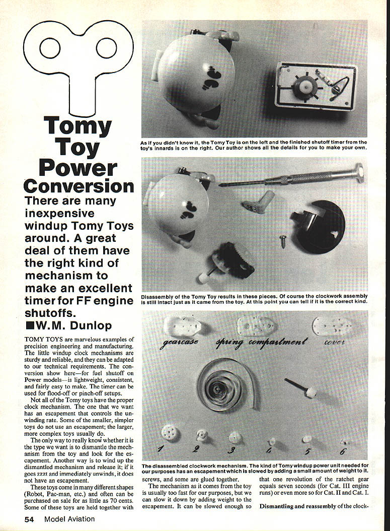
There are many inexpensive windup Tomy Toys available. A great number of them have the right kind of mechanism to make an excellent timer for free-flight (FF) engine shutoffs. Tomy toys contain small windup clock mechanisms that are sturdy, reliable, lightweight, and can be adapted for fuel shutoff on power models. The timer described here can be used for flood-off or pinch-off setups.
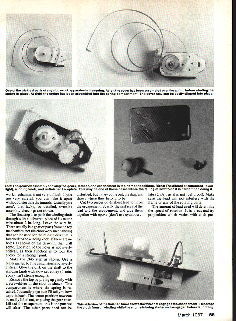
Not all Tomy toys have the proper clock mechanism. The mechanism we want contains an escapement that controls the unwinding rate. Some smaller, simpler toys do not use an escapement; the larger, more complex toys usually do. The only reliable way to know is to dismantle the mechanism and look for the escapement. Another quick test: wind a dismantled mechanism and release it—if it immediately unwinds with a zzzzt sound, it does not have an escapement.
These toys come in many shapes (robot, Pac-Man, etc.) and can often be bought for as little as 70 cents. Some are held together with screws, others are glued.
Preparing the Mechanism
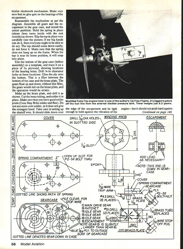
The mechanism as it comes from the toy is usually too fast for our purposes, but it can be slowed by adding a small amount of weight to the escapement. The amount of weight determines the speed of rotation—it is a cut-and-try proposition and varies with each clockwork unit.
Dismantling and reassembly of the clockwork mechanism is not difficult. If you are very careful you can take it apart without disturbing the innards; usually you won't be that lucky, so the instructions below are detailed.
Dismantling Steps
- Push the winding shaft through with a deburred piece of 1/16" music wire about 2" long. Leave the wire in.
- There usually is a gear or part from the toy mechanism that can be used for the release disk that fastens to the winding knob. If there are no holes as required, drill some. Location of the holes is not overly critical; their function is to lock the epoxy for a stronger joint.
- Make a .045" step on the release disk as shown in the original drawing. Use a feeler gauge; the dimension is not overly critical.
- Glue the disk on the shaft to the winding knob with slow-set epoxy (5-minute epoxy isn't strong enough).
- Remove the top by prying up gently with a screwdriver in the slots. This compartment is where the spring is retained. It usually pops out—instructions for putting it back follow.
- Lift out the center partition to expose the gear case. Lift out the escapement—this is the part we will alter. Other parts need not be disturbed, but if they come out, the diagram indicates where they belong.
Adding Weight to the Escapement
- Cut two pieces of 1/32" sheet lead to fit on the escapement.
- Scarify the surfaces of the lead and the escapement, and glue them together with epoxy. Do not use cyanoacrylate (CyA) for this joint; it is not fuel-proof.
- Make sure the lead does not interfere with the frame or any rotating parts.
- The amount of lead used determines the speed of rotation. This varies with each mechanism; add or remove lead by trial and error.
- Be sure no glue gets on the bearings or the escapement.
Reassembly
- Assemble the gears and escapement in the gear case; install the center partition.
- Hold the spring in place with about three turns inside and the rest outside as shown in the diagram. Slip the top plate into place very carefully—the plate should come down easily; do not force it. Make sure the spring does not hang up on the frame top; when near its home position it will snap into place.
- Before final assembly, trace a template from the bottom gear case onto 1/64" plywood showing the locations of the bearing holes. Drill 1/16" clearance holes at these locations.
- Glue the plywood onto the bottom filler between the bottom case and the brass plate so the gears won't float up and down; otherwise the gears would rub the brass plate and operation would be erratic.
Making the Brass Plate and Release Arm
- Make up the brass plate and drill as shown in the diagram.
- Cut brass tubing and solder it in place. Ensure good solder joints—use Stay Brite solder flux and rosin-core solder for a strong bond.
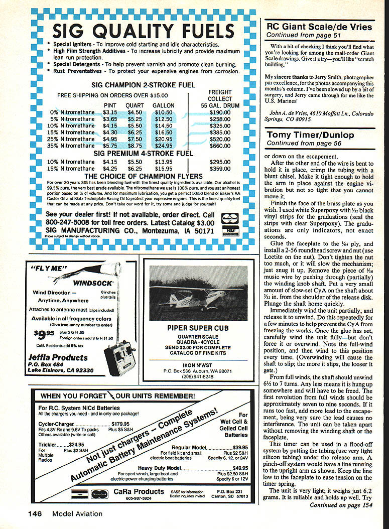
- The shutoff arm should slide down over the edge of the escapement and be tight enough to hold against engine vibration without pushing hard on the escapement.
- After the other end of the wire is bent to hold it in place, crimp the tubing with a blunt punch. Make it tight enough to hold the arm in place against engine vibration but not so tight that you cannot move it.
Faceplate and Final Assembly
- Finish the face of the brass plate as desired. One example: use white Superpoxy with 1/32" black vinyl strips for the graduations (seal the strips with clear Superpoxy). The graduations are only indicators, not exact seconds.
- Glue the faceplate to the 1/64" plywood, and install a 2-56 roundhead screw and nut (use Loctite on the nut). Do not tighten the nut too much or it will slow the mechanism; just snug it up.
- Remove the piece of 1/16" music wire by pushing it partially through the winding knob shaft.
- Put a very small amount of slow-set CyA on the shaft about 1/32" from the shoulder of the release disk. Plunge the shaft home quickly.
- Immediately wind the unit partially and release it to unwind. Repeat this a few minutes to help prevent the CyA from freezing the works.
- Once the glue has set, carefully wind the unit fully—but do not force or overwind. Note the full-wind position and wind to this position every time. Overwinding will cause the shaft to slip; the more it slips, the looser it gets.
Operation and Adjustment
- From full winds, the shaft should unwind 6½ to 7 turns. Any less indicates a hang-up that must be freed.
- The first revolution from a full wind should be approximately 7 to 9 seconds. If it runs too fast, add more lead to the escapement, ensuring no interference with moving parts.
- The unit can be taken apart without removing the winding shaft or the faceplate.
Using the Timer for Shutoff
- This timer can be used in a flood-off system by putting very light silicone tubing under the release arm so that the pinch-off system operates while a line runs to the upright arm as shown in the diagram.
- Keep the line low to the faceplate to reduce tension on the timer spring.
Performance and Maintenance
- The unit is very light—about 6.2 grams. It is reliable and holds up well.
- Try to keep fuel off the mechanism. It generally won't slow down unless it becomes really messy. If it does, take it apart and clean with alcohol.
Notes and Tips
- The selection and amount of lead used on the escapement is critical to timing; expect to experiment.
- Use slow-set epoxy for structural joints and avoid CyA where fuel resistance is required.
- Ensure gears have proper clearance from the brass plate to prevent erratic operation.
Transcribed from original scans by AI. Minor OCR errors may remain.

