
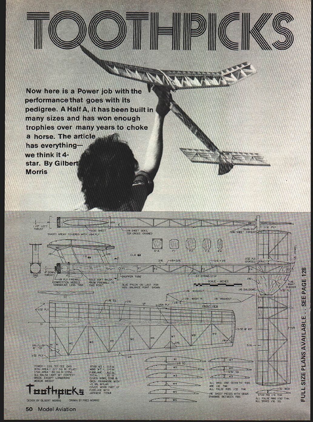
Toothpicks
By Gilbert Morris
Now here is a power job with the performance that goes with its pedigree. A Half-A, it has been built in many sizes and has won enough trophies over many years to choke a horse. The article has everything—we think it 4‑star.
Introduction
Given a few breaks, almost any plane on the field can win a contest. Perhaps this is why even the best fliers run scared. But if you haven't been getting the breaks, take a close look at Toothpicks. It has some unconventional features that can put you in the thick of things.
Toothpicks was conceived with particular attention given to:
- Light construction with a high strength-to-weight ratio
- Low moment of inertia about all axes for stability, transition, and glide
- Low center of lateral area to resist spiral dives
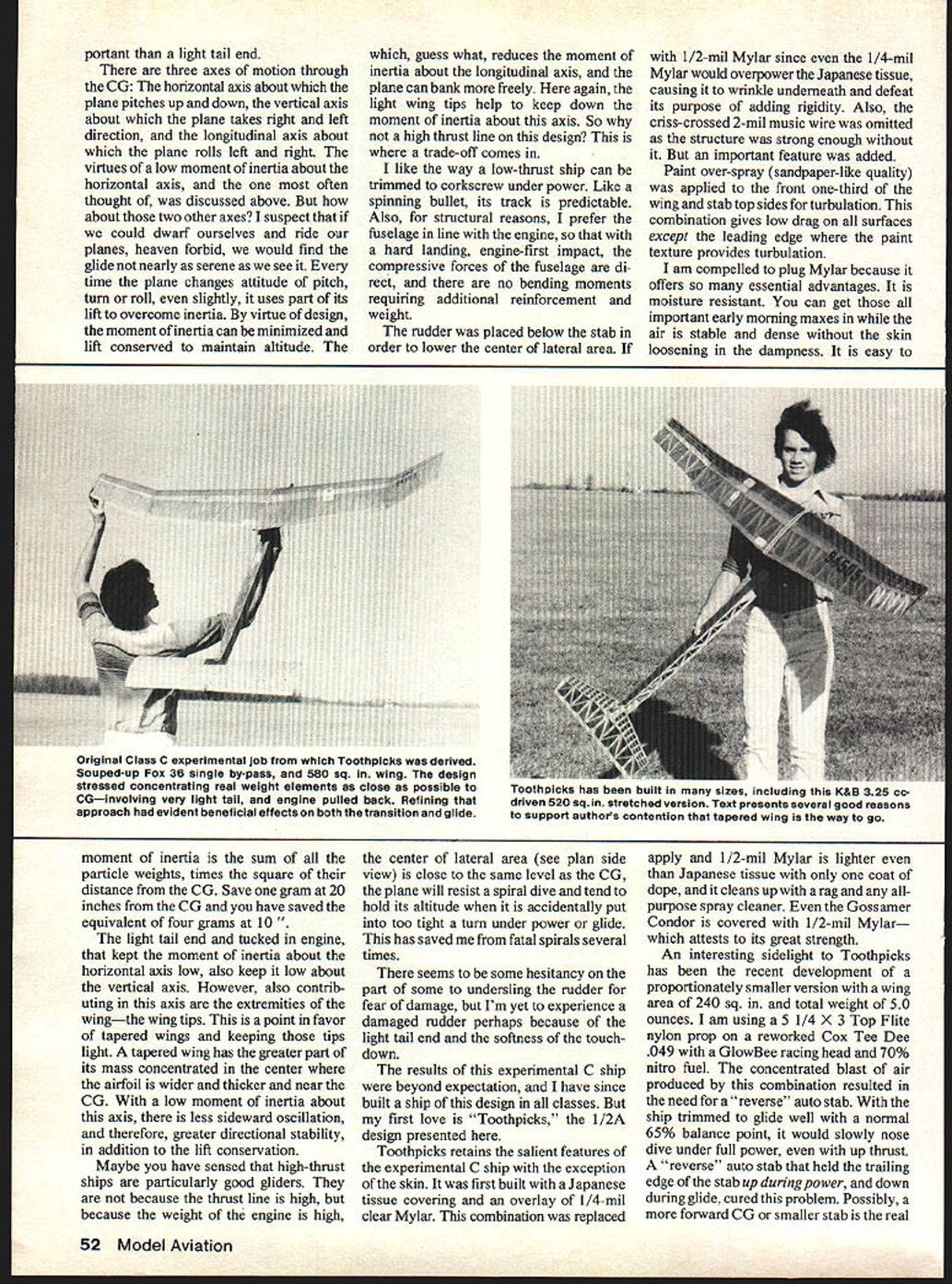
The first design was an experimental Class‑C job designed around a souped-up Fox 36 standard single by‑pass engine with a 580 sq. in. wing. With few exceptions, its features were eventually carried through to Toothpicks.
Wing and covering
The wing was tapered for cantilever strength with a wide-flange beam that locked the geodetic ribs to the main spar. The wing and stab were covered with Silkspan followed by 2‑mil music wire criss‑crossing the top and bottom surfaces to resist warp and flutter. This was followed by a 1/2‑mil Mylar overlay for moisture‑ and fuel‑proofing, and puncture resistance.
Toothpicks retains the salient features of the experimental C ship with the exception of the skin. It was first built with a Japanese tissue covering and an overlay of 1/4‑mil clear Mylar. This combination was replaced with 1/2‑mil Mylar since even the 1/4‑mil Mylar would overpower the Japanese tissue, causing it to wrinkle underneath and defeat its purpose of adding rigidity. Also, the criss-crossed 2‑mil music wire was omitted as the structure was strong enough without it.
Paint over‑spray (sandpaper-like quality) was applied to the front one‑third of the wing and stab top sides for turbulation. This combination gives low drag on all surfaces except the leading edge where the paint texture provides turbulation.
I am compelled to plug Mylar because it offers so many essential advantages. It is moisture resistant — you can get those all-important early morning maxes in while the air is stable and dense without the skin loosening in the dampness. It is easy to apply, and 1/2‑mil Mylar is lighter even than Japanese tissue with only one coat of dope. It cleans up with a rag and any all-purpose spray cleaner. Even the Gossamer Condor is covered with 1/2‑mil Mylar, which attests to its great strength.
Fuselage and inertia considerations
A truss‑type fuselage was used to minimize the moment of inertia. Simply put, this means that the real weight-contributing elements of the plane are concentrated as close as possible to the center of gravity. A light tail end not only keeps the plane extremely light, but in order to balance the plane, the engine must be placed close to the CG, which yields a double benefit since weight is being pulled in from both ends.
This allows the plane to "flip" out of any awkward position it might be in when the engine stops, thereby avoiding the loss of altitude from a recovery dive. This low inertia also improves the glide by allowing the plane to ride up and down freely on minute air waves of the wing, rather than resolutely plowing through them. A plane with a light tail end, and with the engine pulled up under the leading edge of the wing, is also more stable under power — which is a high priority item with engines becoming ever more powerful. I can't think of any single factor more important than a light tail end.
There are three axes of motion through the CG:
- The horizontal axis about which the plane pitches up and down
- The vertical axis about which the plane yaws right and left
- The longitudinal axis about which the plane rolls left and right
The virtues of a low moment of inertia about the horizontal axis were discussed above. But how about the other two axes? Every time the plane changes attitude in pitch, turn or roll, even slightly, it uses part of its lift to overcome inertia. By virtue of design, the moment of inertia can be minimized and lift conserved to maintain altitude.
The moment of inertia is the sum of all the particle weights times the square of their distance from the CG. Save one gram at 20 inches from the CG and you have saved the equivalent of four grams at 10 inches. The light tail end and tucked-in engine that keep the moment of inertia about the horizontal axis low also keep it low about the vertical axis. Contributing to this axis are the extremities of the wing — the wing tips. This is a point in favor of tapered wings and keeping those tips light. A tapered wing has the greater part of its mass concentrated in the center where the airfoil is wider and thicker and near the CG. With a low moment of inertia about this axis, there is less sideward oscillation, and therefore, greater directional stability, in addition to lift conservation.
Light wing tips and a tapered planform also reduce the moment of inertia about the longitudinal axis, so the plane can bank more freely.
Thrust line and structural choices
So why not a high thrust line on this design? This is where a trade-off comes in. I like the way a low‑thrust ship can be trimmed to corkscrew under power. Like a spinning bullet, its track is predictable. Also, for structural reasons, I prefer the fuselage in line with the engine, so that with a hard landing, engine‑first impact, the compressive forces of the fuselage are direct and there are no bending moments requiring additional reinforcement and weight.
Maybe you have sensed that high‑thrust ships are particularly good gliders. They are not because the thrust line is high, but because the weight of the engine is high, which reduces the moment of inertia about the longitudinal axis, and the plane will resist a spiral dive and tend to hold its altitude when it is accidentally put into too tight a turn under power or glide. This has saved me from fatal spirals several times.
The rudder was placed below the stab in order to lower the center of lateral area. There seems to be some hesitancy on the part of some to undersling the rudder for fear of damage, but I’m yet to experience a damaged rudder — perhaps because of the light tail end and the softness of the touchdown.
Small version and pylon/power developments
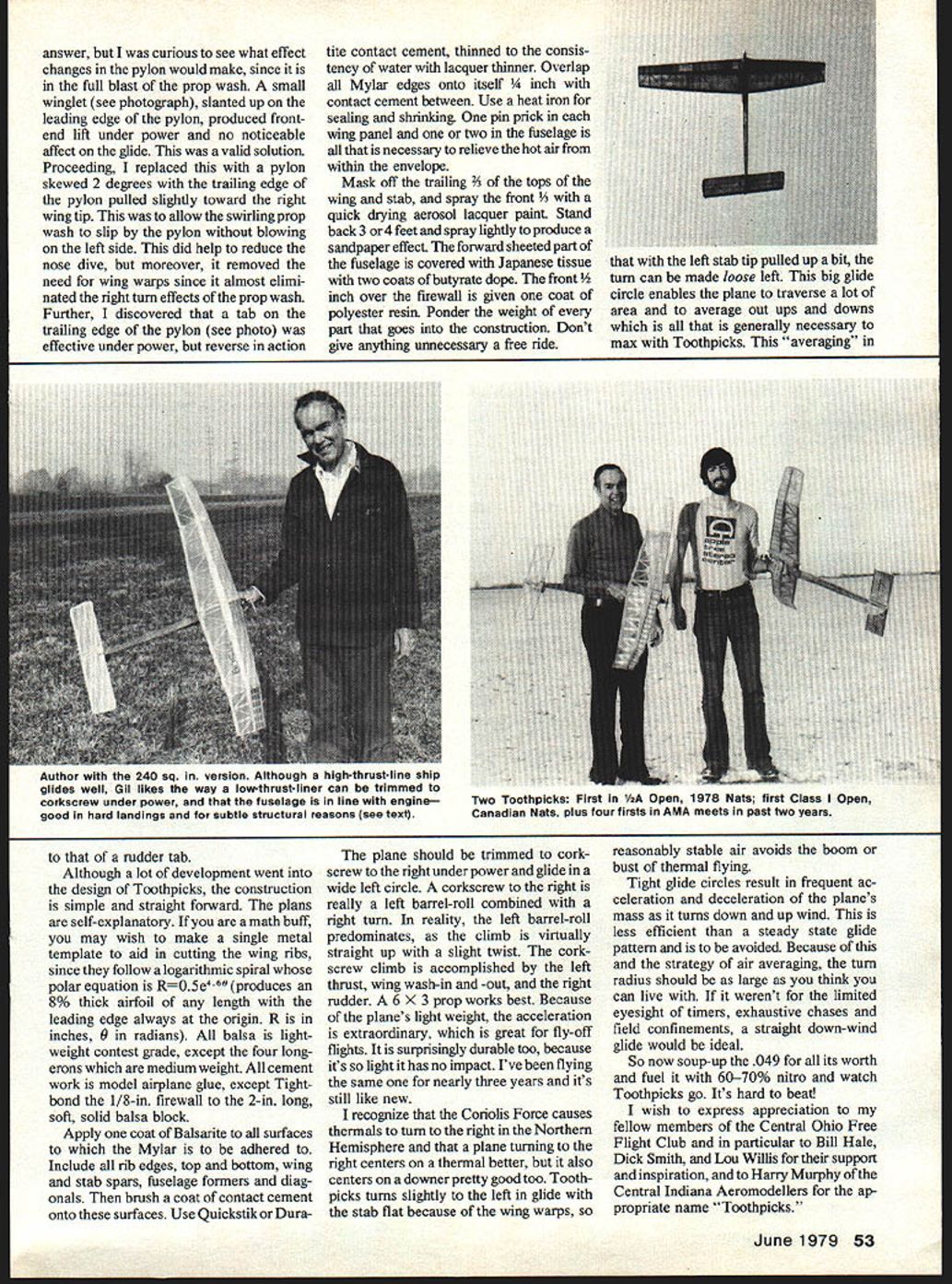
An interesting sidelight to Toothpicks has been the recent development of a proportionately smaller version with a wing area of 240 sq. in. and total weight of 5.0 ounces. I am using a 5 1/4 x 3 Top Flite nylon prop on a reworked Cox Tee Dee .049 with a GlowBeRea racing head and 70% nitro fuel. The concentrated blast of air produced by this combination resulted in the need for a "reverse" auto stab.
With the ship trimmed to glide well with a normal 65% balance point, it would slowly nose dive under full power, even with up thrust. A "reverse" auto stab that held the trailing edge of the stab up during power, and down during glide, cured this problem. Possibly, a more forward CG or smaller stab is the real cure, but I was curious to see what effect changes in the pylon would make, since it is in the full blast of the prop wash.
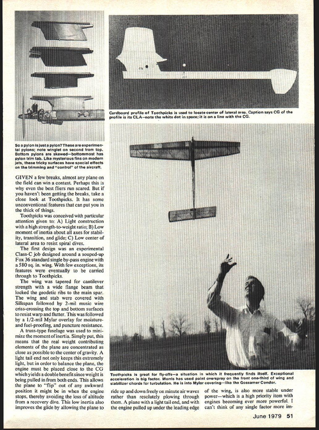
A small winglet, slanted up on the leading edge of the pylon, produced front-end lift under power and no noticeable effect on the glide. This was a valid solution. Proceeding, I replaced this with a pylon skewed 2 degrees with the trailing edge of the pylon pulled slightly toward the right wing tip. This was to allow the swirling prop wash to slip by the pylon without blowing on the left side. This did help to reduce the nose dive, but moreover, it removed the need for wing warps since it almost eliminated the right-turn effects of the prop wash. Further, a tab on the trailing edge of the pylon was effective under power, but reverse in action to that of a rudder tab.
Construction details and tips
Although a lot of development went into the design of Toothpicks, the construction is simple and straightforward. The plans are self-explanatory. If you are a math buff, you may wish to make a single metal template to aid in cutting the wing ribs, since they follow a logarithmic spiral whose polar equation is: R = 0.5 e^(0.66θ) This produces an 8% thick airfoil of any length with the leading edge always at the origin. R is in inches, θ in radians.
Materials and glue:
- All balsa is lightweight contest grade, except the four longerons which are medium weight.
- All cement work is model airplane glue, except use Tightbond for gluing the 1/8-in. firewall to the 2-in. long soft solid balsa block.
Covering Mylar:
- Apply one coat of Balsarite to all surfaces to which the Mylar is to be adhered. Include all rib edges, top and bottom, wing and stab spars, fuselage formers and diagonals.
- Then brush a coat of contact cement onto these surfaces. Use Quickstik or Dura-Tite contact cement, thinned to the consistency of water with lacquer thinner.
- Overlap all Mylar edges onto itself 1/4 inch with contact cement between.
- Use a heat iron for sealing and shrinking. One pin prick in each wing panel and one or two in the fuselage is all that is necessary to relieve the hot air from within the envelope.
Finishing:
- Mask off the trailing 3/8 of the tops of the wing and stab, and spray the front 5/8 with a quick-drying aerosol lacquer paint. Stand back 3 or 4 feet and spray lightly to produce a sandpaper effect.
- The forward sheeted part of the fuselage is covered with Japanese tissue with two coats of butyrate dope.
- The front 1/2 inch over the firewall is given one coat of polyester resin.
- Ponder the weight of every part that goes into the construction. Don't give anything unnecessary a free ride.
Trimming and flying
I found that with the left stab tip pulled up a bit, the turn can be made loose left. This big glide circle enables the plane to traverse a lot of area and to average out ups and downs which is all that is generally necessary to max with Toothpicks. This "averaging" in reasonably stable air avoids the boom-or-bust of thermal flying.
The plane should be trimmed to corkscrew to the right under power and glide in a wide left circle. A corkscrew to the right is really a left barrel-roll combined with a right turn. In reality, the left barrel-roll predominates, as the climb is virtually straight up with a slight twist. The corkscrew climb is accomplished by the left thrust, wing wash-in and -out, and the right rudder. A 6 x 3 prop works best.
Because of the plane's light weight, the acceleration is extraordinary, which is great for fly-off flights. It is surprisingly durable too, because it's so light it has no impact. I've been flying the same one for nearly three years and it's still like new.
I recognize that the Coriolis force causes thermals to turn to the right in the Northern Hemisphere and that a plane turning to the right centers on a thermal better, but it also centers on a downer pretty well too. Toothpicks turns slightly to the left in glide with the stab flat because of the wing warps, so reasonably stable air avoids the boom-or-bust of thermal flying.
Tight glide circles result in frequent acceleration and deceleration of the plane's mass as it turns down and up wind. This is less efficient than a steady-state glide pattern and is to be avoided. Because of this and the strategy of air averaging, the turn radius should be as large as you think you can live with. If it weren't for the limited eyesight of timers, exhaustive chases and field confinements, a straight downwind glide would be ideal.
So now soup-up the .049 for all it's worth and fuel it with 60–70% nitro and watch Toothpicks go. It's hard to beat!
I wish to express appreciation to my fellow members of the Central Ohio Free Flight Club and in particular to Bill Hale, Dick Smith, and Lou Willis for their support and inspiration, and to Harry Murphy of the Central Indiana Aeromodellers for the appropriate name "Toothpicks."
Transcribed from original scans by AI. Minor OCR errors may remain.

