
Top Cat 90L-1
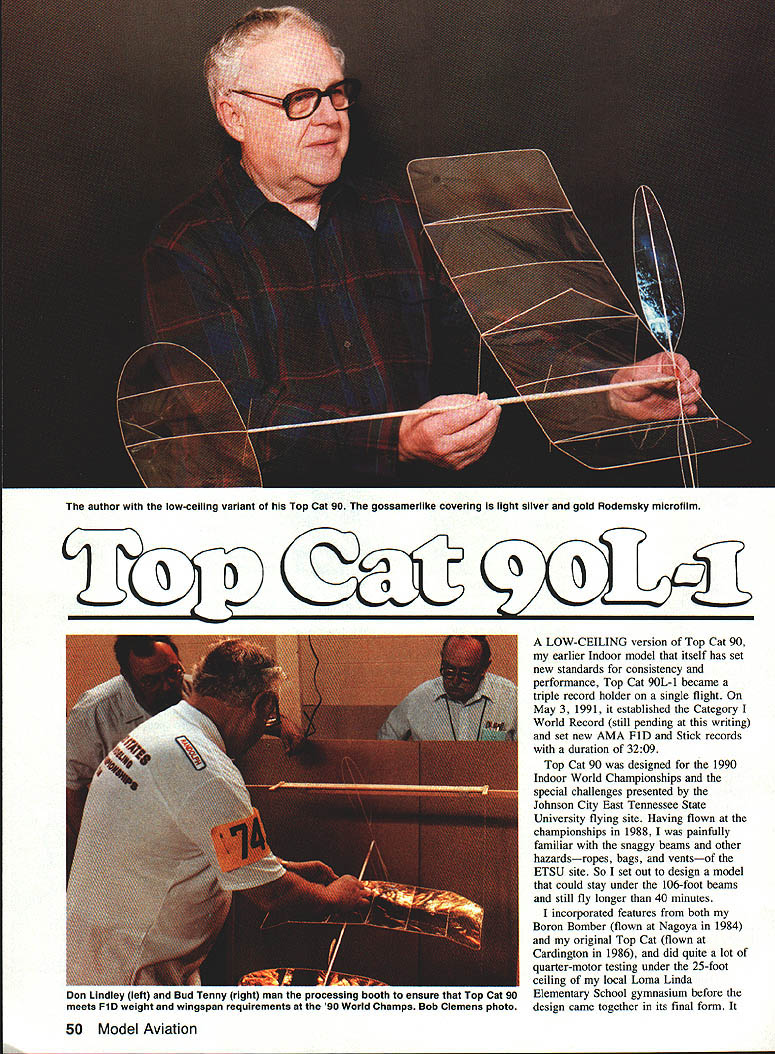
A low-ceiling version of Top Cat 90, my earlier indoor model that set new standards for consistency and performance, Top Cat 90L-1 became a triple-record holder on a single flight. On May 3, 1991, it established the Category I World Record (still pending at the time) and set new AMA F1D and Stick records with a duration of 32:09.
Top Cat 90 was designed for the 1990 Indoor World Championships to meet the special challenges presented by the Johnson City, East Tennessee State University flying site. Having flown the championships in 1988, and being painfully familiar with snaggy beams and other hazards—ropes, bags, vents—at ETSU, I set out to design a model that could stay under the 106-foot beams and still fly longer than 40 minutes. The design incorporated features from both the Boron Bomber (Nagoya 1984) and the original Top Cat (Cardington 1986). I did extensive quarter-motor testing under the 25-foot ceiling of Loma Linda Elementary School gymnasium before the design came together.
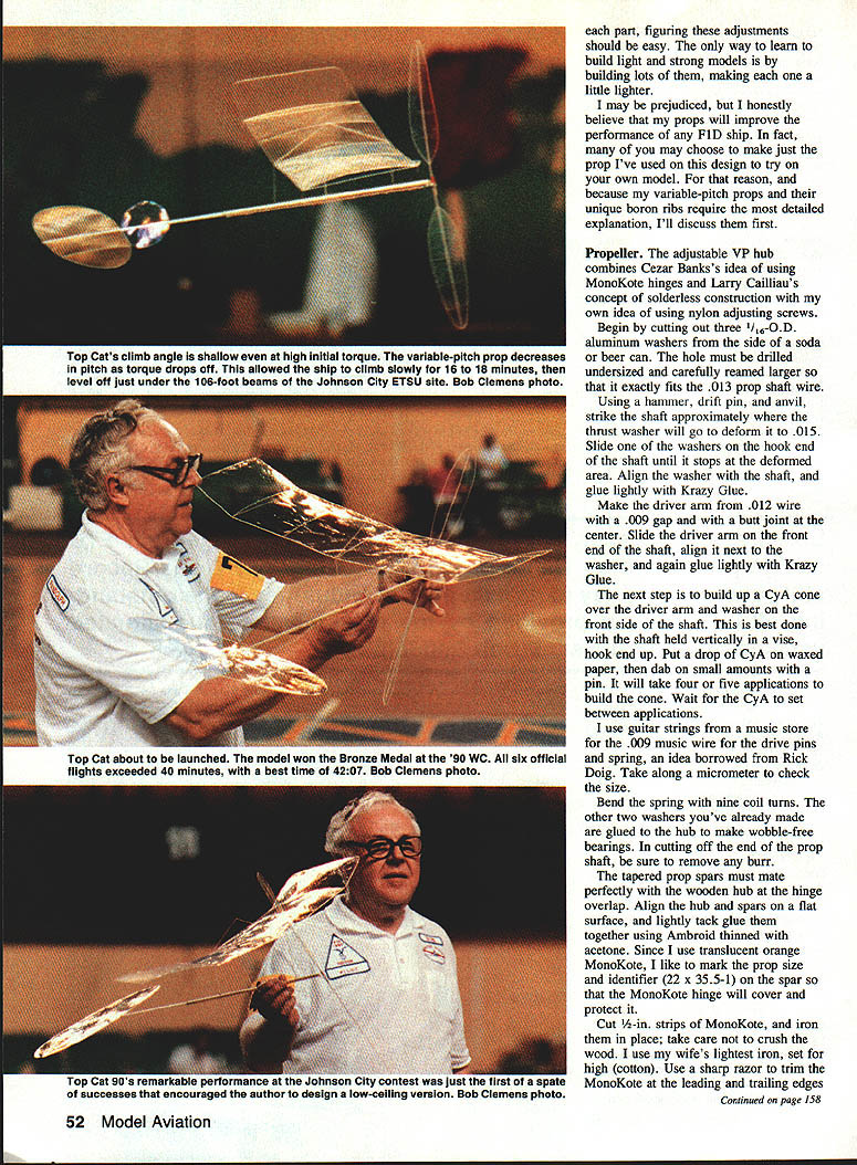
Flight tests of three prototypes indicated the design goals would be met. The reliable torque-actuated variable-pitch (VP) propeller uses a tiny 00-90 screw to adjust the maximum (high) pitch and is able to change pitch over the rubber motor’s decaying torque curve so that slightly greater cruise thrust can be maintained.
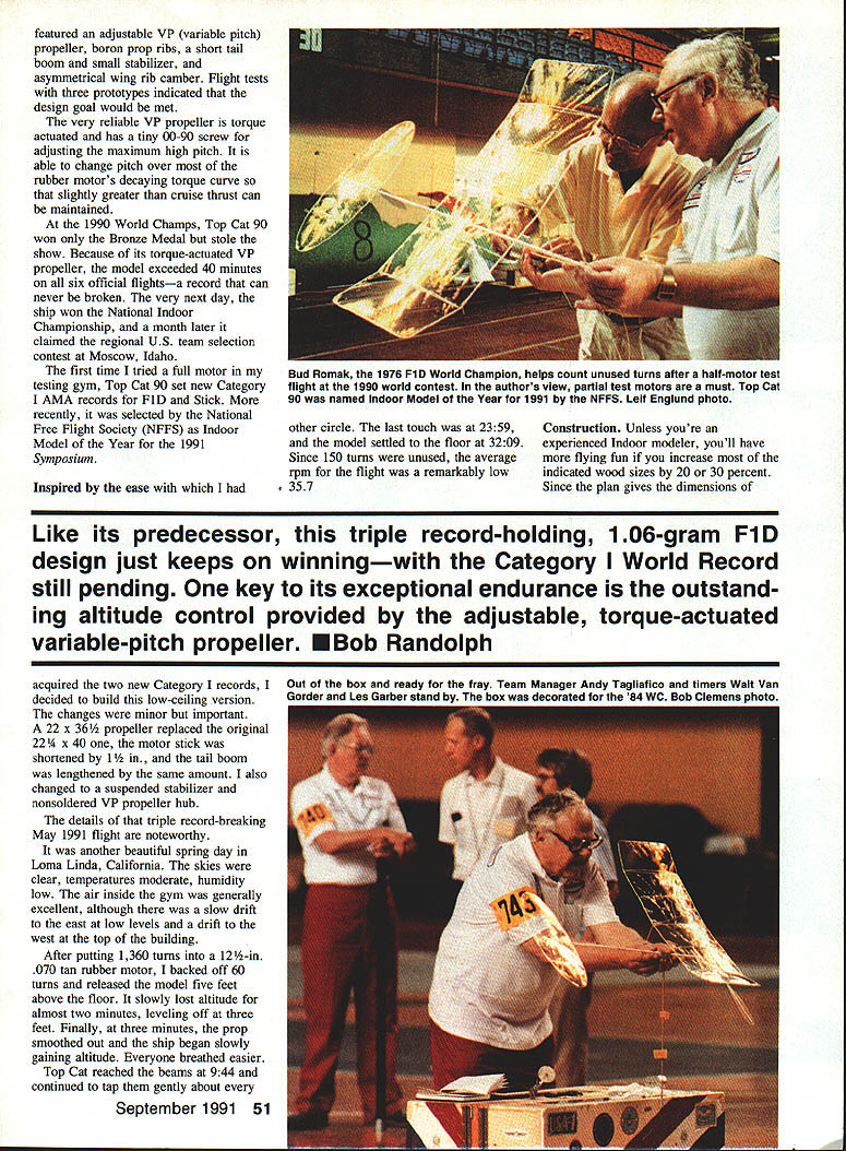
At the 1990 World Championships Top Cat 90 won the Bronze Medal. Because its torque-actuated VP propeller allowed the model to exceed 40 minutes on six official flights—a record that can never be broken—the next day it won the National Indoor Championship. A month later it won the regional U.S. team selection contest in Moscow, Idaho. The first time full-motor testing was tried in the gym, Top Cat 90 set new Category AMA records (F1D and Stick) and was selected National Free Flight Society (NFFS) Indoor Model of the Year 1991.
Construction
Unless you’re an experienced indoor modeler you’ll have more flying fun if you increase the indicated wood sizes by 20–30 percent, since the plan gives dimensions. Like its predecessor, the triple-record-holding 106-gram F1D design just keeps winning. The key is exceptional endurance and outstanding altitude control provided by the adjustable torque-actuated variable-pitch propeller.
For the low-ceiling version I made a few important changes: a 22 x 36½-in. propeller replaced the original 22¼ x 40-in. one, the motor stick was shortened by 1½ in., and the tail boom was lengthened by the same amount. I also changed to a suspended stabilizer and consolidated the VP propeller hub.
The triple record–breaking May 1991 flight was noteworthy. It was a beautiful spring day in Loma Linda, California—clear skies, moderate temperatures, low humidity. The air inside the gym was generally excellent, with a slow drift east at low levels and a drift west near the top. After putting 1,360 turns into a 12½-in. .070 tan rubber motor, I backed off 60 turns and released the model five feet above the floor. It slowly lost altitude for almost two minutes, leveling off at about three feet. At three minutes the prop smoothed out and the ship began slowly gaining altitude. Top Cat reached the beams at 9:44 and continued to tap them gently until about the last touch at 23:59; the model finally settled to the floor at 32:09, with 150 turns unused. The average rpm during the flight was remarkably low, about 357 rpm.
Each part should be built light and strong; the only way to learn that is by building lots of them and making each one a little lighter.
Because my variable-pitch props and their unique boron ribs require the most detailed explanation, I discuss them first below.
Propeller
The adjustable VP hub combines Cezar Banks’s idea of using MonoKote hinges, Larry Caillau’s concept of solderless construction, and my use of nylon adjusting screws.
- Cut three 1/16-in.-o.d. aluminum washers from a soda or beer can. Drill the hole undersized and carefully ream it so it fits the .013-in. prop shaft wire exactly.
- Using a hammer, drift pin, and anvil, strike the shaft where the thrust washer will go to deform it to about .015 in. Slide one washer onto the hook end of the shaft until it stops at the deformed area. Align and glue lightly with Krazy Glue.
- Make the driver arm from .012-in. wire with a .009-in. gap and a butt joint at the center. Slide it on the front of the shaft, align next to the washer, and glue lightly.
- Build up a CyA cone over the driver arm and washer on the front side of the shaft with several light applications of CyA. Hold the shaft vertically in a vise, hook end up.
- Use guitar strings (music-store wire) for the .009-in. music wire drive pins and spring—check size with a micrometer. Bend the spring with nine coil turns. Glue the other two washers to the hub for wobble-free bearings. Remove any burr when cutting off the end of the prop shaft.
- Ensure the tapered prop spars mate perfectly with the wooden hub at the hinge overlap. Align hub and spars on a flat surface and tack-glue with Ambroid thinned with acetone. Mark the prop size and identifier (e.g., 22 x 35.5-1) on the spar before covering.
- Cut 1/16-in. strips of MonoKote and iron them in place carefully (use a light iron set for high/cotton). Trim the MonoKote at leading and trailing edges with a sharp razor.
- Dissolve the tacked-on glue with liberal acetone so the hinges have freedom of movement; the MonoKote bond is not affected. Make L-pins about 1/8-in. overlength and glue them to the spars. Slip the shaft onto the hub, applying preload torque so the driver can be slipped onto the pins.
- Fit the adjust-and-screw assembly so it lines up with the driver arm and clears the spring end and prop spar. Sand or file the end of the nylon adjusting screw flat to prevent the driver arm from slipping off at high torque.
- Build prop blades flat in a cardboard female template. Break off boron ribs so they can be positioned on the outline without extending beyond it. Glue bits at leading and trailing edges, then glue balsa spars under each boron rib on the spar centerline. When dry, mark the exact centerline.
- Tack-glue the prop spar on a prop block (40-in. pitch for Top Cat 90; 36½-in. pitch for the 90L-1). Glue ribs from tip to hub, lining up marks on the spacers over the spar center. Wet the outline gradually as you glue to hold the rib helix shape of the block. Fasten the other blade in the same manner.
- To put camber in the ribs: place the prop on the building board with the rear of one blade up. Beginning at the tip, glue a length of Kevlar to the leading edge over the first rib. Tension the Kevlar to obtain the desired camber by squeezing it just past the trailing edge, glue it to the trailing edge, and glue again where it crosses the spar. Trim excess after the glue dries.
- I use boron prop ribs for strength and lightness and Triple-R blue microfilm for covering. To make microfilm stick to boron ribs, moisten a brush with saliva and flick across the boron so small droplets form at roughly 1/4-in. intervals along the rib; then apply the film and blow down gently.
Place the prop on a prop block during covering for uniform pitch and smooth running.
Wing
Construction is conventional except for the tips, boron-stiffened wing posts, and Kevlar bracing. I use built-up compression ribs (not tapered) because they withstand the high-torque strain produced by the variable pitch; these ribs can be sliced off and sanded as needed.
- Cut wing spars at the dihedral points and tack-glue them flat.
- Bend the wing tips around a 1-in.-dia. heated curling iron to form small dihedral curves. Mark the center of each arc and moisten the wood before bending; you may need to repeat as the wood tends to spring back.
- Cover the wing flat and add trim. Brush the dihedral joints with acetone, then dab-glue the wing to the correct dihedral angles.
- Add two boron reinforcements to the wing posts—essential to stiffen the posts. To fit tissue wing sockets, repeatedly snap a micrometer on the post ends until they squeeze down to .058 in.
- Install Kevlar bracing for a stiff wing; the weight and drag of Kevlar are negligible. The center rib may have too little camber after bracing—correct this by gluing a tensioned Kevlar bowstring under the rib using the same technique as for prop rib camber.
Motor stick and tail boom
These are formed from metal forms following standard soaking, rolling, and baking procedures. Glue the seams and boron with a hypodermic needle.
To avoid curved tail booms from glue shrinkage, use the Joe Foster technique: mount the large end of the boom form horizontally in a vise, slip the baked boom onto the form, and clamp down the small end about 3/16 in. to produce a bow. Glue the seam along the top of the form—the shrinkage will straighten the seam as the glue dries.
Rudder
- The trailing edge of the rudder-and-post is 4-5/8 x 27 x 3/16-000. The leading edge is an 8½-in. length of boron. Pierce the post 1/16 in. from the end with the boron and glue it in place. When dry, bend the boron around, pierce the other end, and glue.
- Glue on the boron adjusting arm and install a horizontal Kevlar brace before covering.
- Make a razor slot in the post ends before covering to ease later stab adjustment.
- Cover the rudder on a firm frame and wet the outline; trim the microfilm with a hot wire rather than acetone.
Stabilizer and tail assembly
- Cut stabilizer spars from tapered wood and join the two halves with a scarf splice glued with CyA. Install the three ribs and lay them flat for covering and trimming.
- Shim the leading edge of the stab so it’s centered on the boom end and glue it in place. Position and glue the rudder on the boom.
- Attach the .0003-in. tungsten stab bracing to the left side of the boom away from the rudder. Insert the boom in the motor stick and use a jig to provide 1° negative incidence; glue in place.
Wing sockets and center-of-gravity
- Weigh the model. Make a dummy motor weighted to 1.25 times the amount and use dummy weight for the wing. Tack-glue the dummy motor weight onto the stick midway between the prop shaft hook and the tail hook. Move the wing weight until the model balances 56% back from the wing front post and mark the socket locations.
- This center-of-gravity location compensates for the small stab, short tail boom, and high prop pitch at launch to provide necessary stability.
- The holes for the sockets go all the way through the stick and must be carefully drilled to achieve the required 1/2-in. stab tilt.
VP propeller adjustment
- Measure the torque required for cruise (level flight) by flight testing. Remove the prop and adjust the preload tension so the hinges just begin to open from low pitch when this torque is applied to the prop shaft.
- Do more test flights to find the motor length and size that will use up almost all the turns when descending from top altitude—this is the optimum motor. Avoid the old one-third-knot-on-landing standard; instead, avoid overclimbing the site. Back off turns to reduce launch torque and work up slowly to top altitude.
- Using the optimum motor, back off less each time and open the high-pitch screw. When you achieve a climb that begins with minimal altitude gain, use this torque value for all flights. With torque kept constant, small adjustments with the high-pitch screw give outstanding altitude control.
Low-ceiling problems
Propeller adjustment is the same for low ceilings, but flying is more critical:
- Reduce climb rate by a factor of almost four to avoid the ceiling; the initial climb rate will be close to zero.
- Small differences in blade pitch at high launch torque can cause oscillation and loss of altitude.
- Launch speed and attitude are critical. With very little forward thrust you must provide some airspeed at launch so the wing and stab can take hold.
- Be careful that your body turbulence doesn’t ruin the launch.
O-rings
O-rings are essential. They allow you to transfer a wound motor from a torque meter to the model without loss of turns and torque. I use two O-rings on full motors and one on partial motors.
Partial motors
Different flying sites and weather change power requirements. Using partial test motors speeds and safes the task of finding the new optimum motor length and size.
- Example: a quarter-size test motor requires a test stick exactly three-fourths of the distance between the hooks and weighted to exactly three times the lubed weight of the quarter-motor. With only one-fourth of the full motor turns, the model should climb to one-fourth of its previous altitude and fly one-fourth the time—allowing four times as many test flights.
- Errors in altitude estimation are compounded, so be conservative. I often run a helium balloon up to the beams and mark the line at 30% and 25% locations to improve height estimates.
- When fairly certain of optimum length and size for a quarter-motor, verify with a half-motor if time permits. In 1985 and again at the 1990 Nationals I went from a 10+ minute quarter-motor test directly to an official full-motor flight with only a few seconds deviation from predicted correlation.
Partial-motor testing has great merit. Often full-motor flights will be slightly higher and longer because of warmer air near the site ceiling.
Easy to build, adjust, and fly, this national and world record–holding model has brought me great pride and pleasure. I hope it will do the same for you.
Recommended Indoor Suppliers
- Indoor Model Supply
Box 5311 Salem, OR 97304
- Micro-X Products
5200 Seven Pines Drive Lorain, OH 44053
- F.A.I. Model Supply (FAI tan rubber)
Box 3954 Torrance, CA 90510
- Ery Rodemsky (microfilm)
1600 Rockspring Place Walnut Creek, CA 94596
- Bob Oppegard (rubber cutters)
140 East Golden Lake Lane Circle Pines, MN 55014
Transcribed from original scans by AI. Minor OCR errors may remain.

