
TR-260
By Brad Shepherd
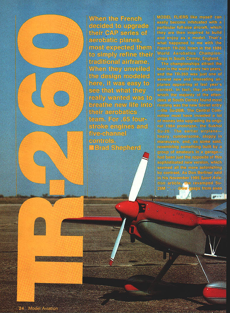
When the French decided to upgrade their CAP series of aerobatic planes, most expected a refinement of the traditional airframe. Instead they unveiled the TR-260, a design that breathed new life into their aerobatics team. The model presented here is intended for .65 four-stroke engines and five-channel controls.
Model fliers often get infatuated with a full-size airplane and build a model from that inspiration. That's what happened to me after seeing the French TR-260 at the 1986 World Aerobatics Championships in South Cerney, England. The championships draw the best in the world every two years, and the TR-260 was one of several interesting new airplanes there.
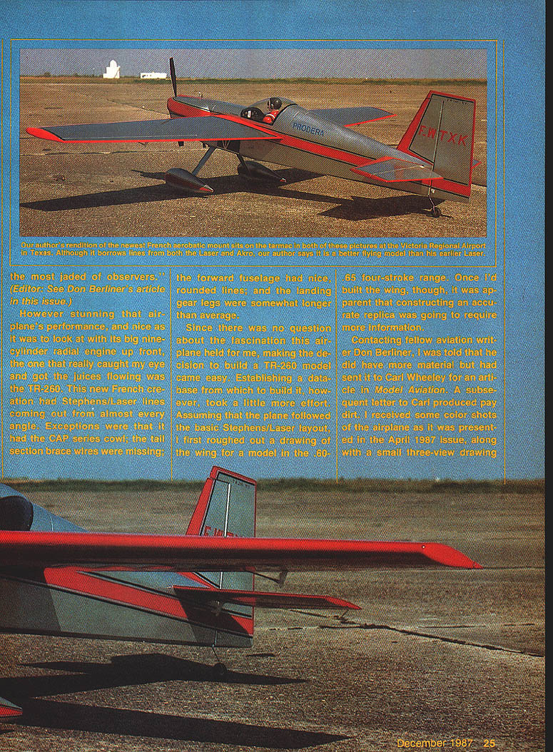
Although the Soviet Su-26M stole many headlines with its dramatic performance, the TR-260 caught my eye. It showed Stephens/Laser lines from almost every angle, yet retained a CAP-series cowl, longer-than-average landing gear legs, and a nicely rounded forward fuselage. The tail lacked the CAP tail-section brace wires, giving it a cleaner look.
Research and preliminary layout required some work. Don Berliner had material forwarded on to Carl Wheeley for an article in Model Aviation; that April 1987 issue provided a small three-view drawing and some French metric notes—enough to move the project along. Comparing the three-view with Laser variations and photos helped firm up shapes. Because the stabilizer appeared lower in relation to the thrust line than on the Lasers, I adopted that arrangement. Tail-section airfoils were constructed in the same manner as the CAP series, but slightly thinner, which simplified construction.
I don't know whether Don would file the TR-260 under "ugly" or "beautiful," but I do know this: it's a beautiful-flying airplane that should please any modeler.
FRENCH TR-260 — Test Flights and Performance
My first test flights with the TR-260 were in March 1987. My flying buddy Leon Folse and I drove to a friend’s mowed flatland — a fabulous flying site with close‑cropped grass and no obstacles — and spent a pleasant afternoon flying.
A safety note: I had a close call while starting the engine. I used a CG 2-1/2‑in. spinner with a Master Airscrew 13‑6 prop. The spinner was reworked to enlarge the cutouts to accept the prop, and I filed a little off the prop for fit. After the engine fired and I advanced the throttle, the prop and spinner came off. The prop struck my right hand between thumb and forefinger, producing a two‑inch gash. The bleeding stopped and I did not require stitches, but the incident convinced me the spinner arrangement was unsafe for a four‑stroke of that size. I flew subsequent tests without a spinner until a better setup could be devised.
Weight and power:
- Goal: 6 to 6-1/2 lb to be acrobatic on a .65 four-stroke and to have good vertical capability.
- Final weight: 6 lb 12 oz (slightly over goal, but performance was not hindered).
- Powerplant: Saito .65 four-stroke — considerably more powerful than I had estimated.
Flight impressions:
- On the first takeoff the model literally jumped off the ground as the throttle opened. I let it climb straight while trimming the servos, then made a hands‑off run along the field to confirm trim.
- Maneuvers included loops with snaps, inside and outside loops, square loops, hammerheads, vertical rolls, four‑point rolls, and more. On a vertical climb with a snap roll the model kept climbing strongly — a testament to the Saito’s power.
- On the second flight I flew inverted passes into outside loops with outside snaps on top. Leon, who flew business jets before retiring, pronounced the TR-260 far superior to the Laser I had designed earlier — high praise, since I had regarded that Laser as my best flying design.
CONSTRUCTION
To create a model with the talents of a full‑size aerobatic ship while keeping weight down, I used light, careful building techniques throughout.
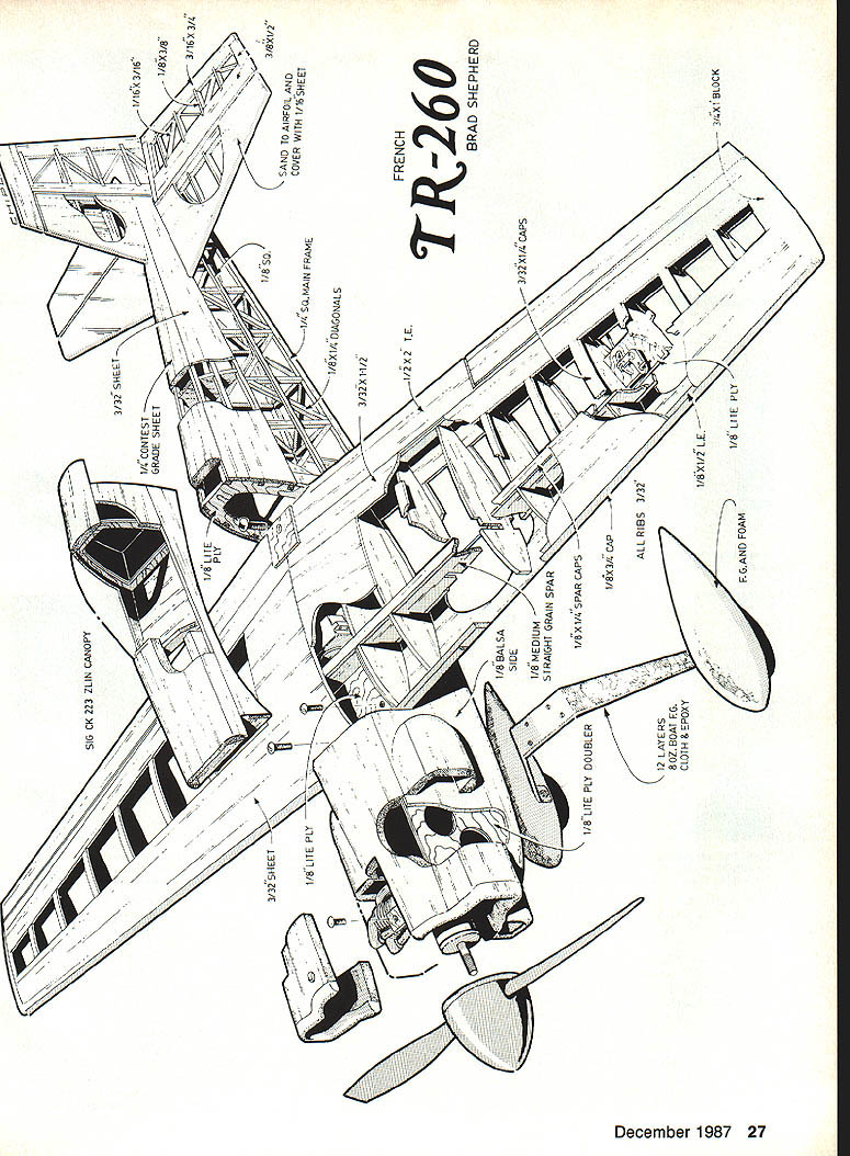
Wing
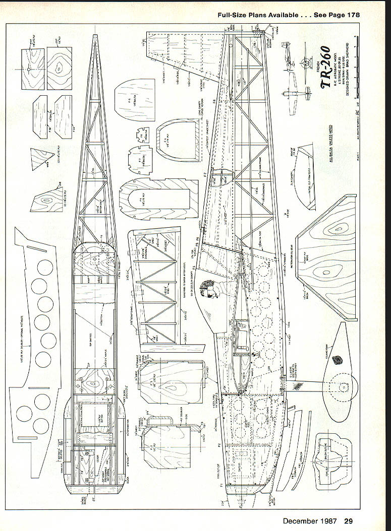
- Any standard method for cutting ribs for a tapered wing is appropriate. A full set of ribs is laid out on the plans for tracing or copying.
- My method for transferring parts to wood: make a tracing, spray contact cement on the paper, press it on the wood, cut out parts, then peel the paper off.
- The lightweight construction may look fragile, but the box spar is lighter and stiffer than two large balsa sticks and resists twisting. A straight workbench guarantees a straight wing.
- Materials and construction highlights:
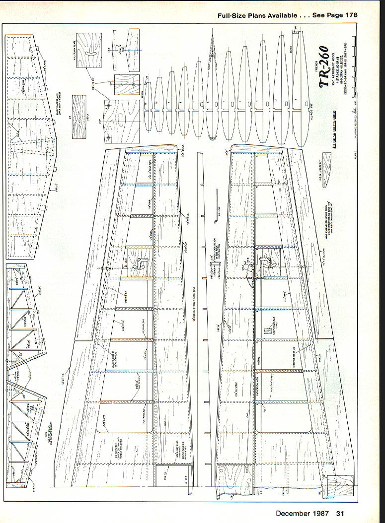
- Use medium‑to‑hard, straight‑grained 1/8‑in. balsa for spars.
- Jig at trailing edge: 3-1/4 in. long, 3/8 in. at rib #1 tapering to 1/4 in. at rib #11.
- Pin a 1/8 x 1/4‑in. cap to the plans; glue the spar, slots up, into the leading edge (LE).
- Trial-fit, trim ribs, pin to spar and jig, then tack joints with thick CYA.
- Glue 1/8 x 1/4‑in. cap along the top of the spar, and glue a 1/8 x 1/2‑in. LE to the ribs.
- Glue a 1/8 x 3/8‑in. strip to the edge of a 3/32 x 1-1/2‑in. quarter‑grain sheet and glue it to the ribs so the strip butts against the TE.
- For LE sheeting, select medium, straight‑grained 3/32‑in. sheet. Sand a bevel into the LE to match the rib shape. Use aliphatic resin glue for main sheeting; a bead of thick CYA can help hold pieces while resin cures.
- Do not sheet the center section or the area inside rib #1 on the LE until later.
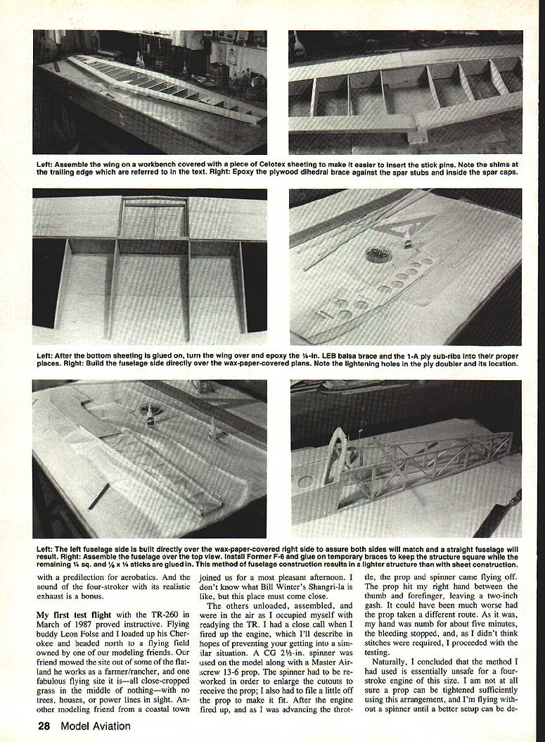
- After both panels are completed, lay them upside down on a straight line on the bench, shim the center section TE 1/16 in., shim outboard rib #11 TEs 1/4 in., and pin securely.
- Epoxy the 1/8‑in. ply dihedral brace to spar stubs inside the spar caps. Glue TE and LE 1/4‑in. balsa braces, and glue bottom center‑section sheet. Epoxy 1/8‑in. ribs in place and epoxy the ply plate LE panel to the spar and LE.
- Sheet the center section behind the spar only; leave the area over the ply plate uncovered until after the wing is bolted to the fuselage.
- Cut and fit 1/2 x 2‑in. TE stock, dry‑fit and glue with CYA while holding the panels down to ensure a true TE.
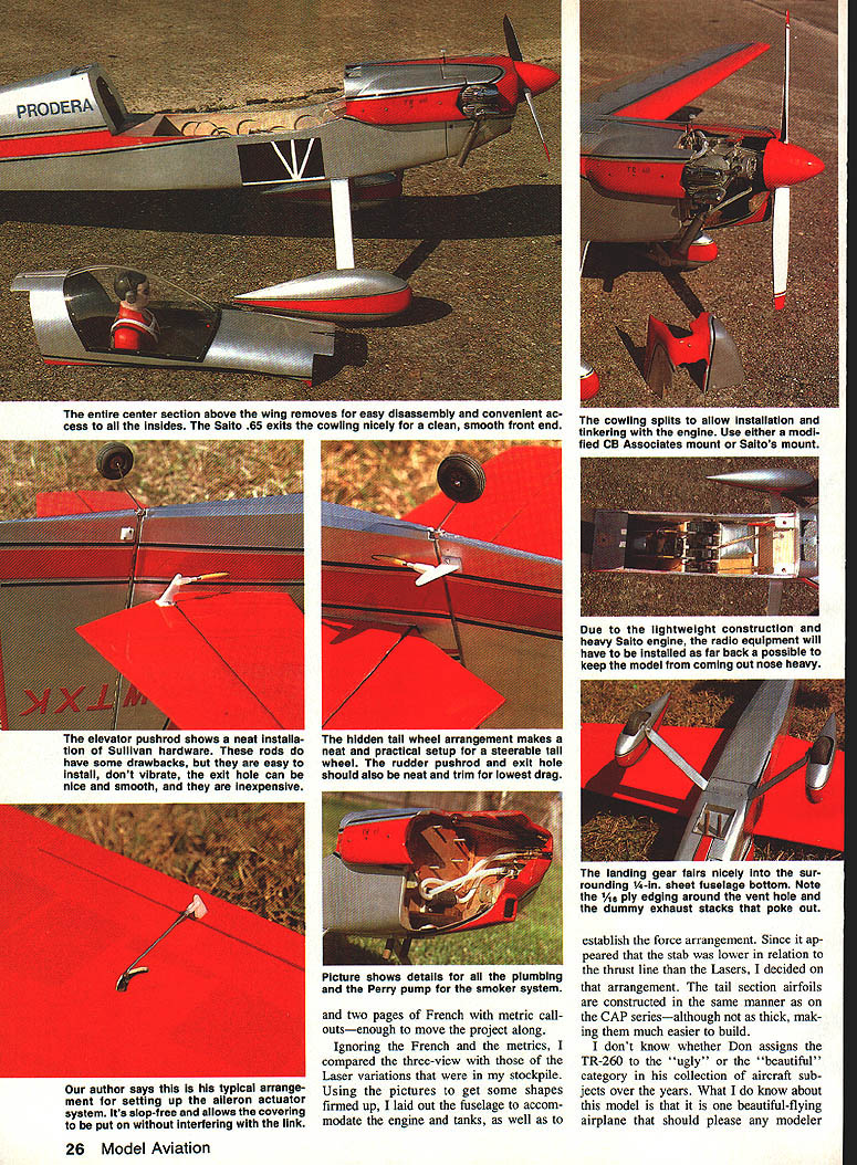
- Lay out ailerons, cut from TE stock, install block tips, aileron crank plate, 1/16‑in. music‑wire pushrods and 1/8‑in. ply fairleads.
Fuselage
- To save weight versus full sheeted fuselage and full‑depth Lite Ply doublers, sheet only in stress areas and lighten the ply doublers with holes; build the remainder with sticks. This proved strong and light.
- Cut doublers and lay out 1/8‑in. side sheets. Piece sheet as necessary using CYA.
- Lay out balsa sides using the thrust line as benchmark. Glue doublers to sides with contact cement and reinforce edges with CYA.
- Construct aft lower section of sides using 1/4‑in. square and 1/4 x 1/2‑in. balsa. Trace and cut former patterns, then contact cement to ply where noted.
- Build each fuselage side over wax paper on the plans. Build the left side over the wax‑paper‑covered right side to ensure matching sides and a straight fuselage.
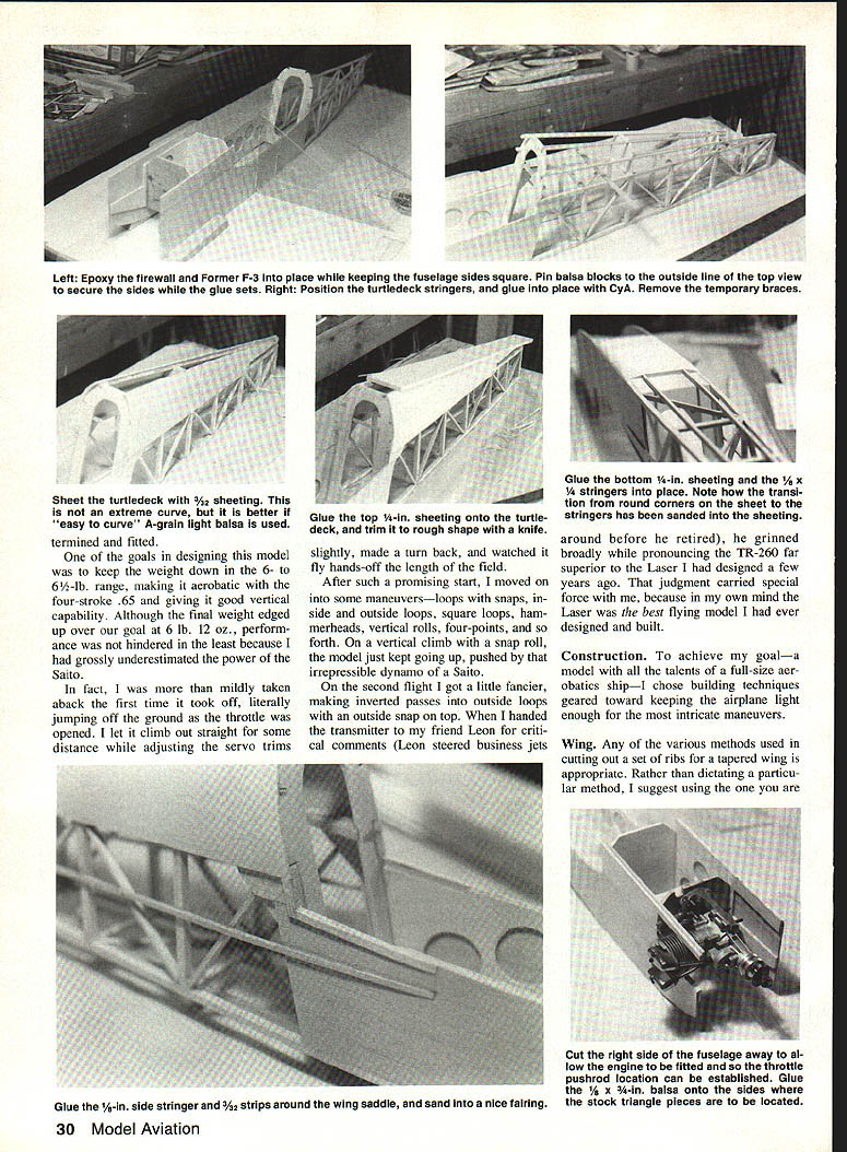
- Install F‑6 temporarily, brace sides 90° to the workbench, glue tail post and F‑6 when square.
- Glue 1/4‑in. crosspieces and 1/4 x 1/2‑in. diagonals. Add 1/8‑in. balsa gussets to top longeron joints at F‑6.
- Re‑pin and install front formers F‑3 and F‑2, epoxy in place. Trial fit F‑7 and F‑8 and align stringers and formers before gluing.
- After bottom sheeting is glued, epoxy a 1/4‑in. LE balsa brace and 1/8‑in. ply sub‑ribs in place.
- The entire center section above the wing is removable for easy disassembly and access. Landing gear fairings are formed around the 1/8‑in. sheet fuselage bottom; note 1/8‑in. ply edging around the vent hole.
- Install tanks and plumbing as required; the prototype used a Perry pump smoker system and plumbing details shown in photos. Use either a modified CB Associates mount or Saito's mount for the engine; the CB mount can be trimmed to allow the engine to slide back without interfering with throttle controls.
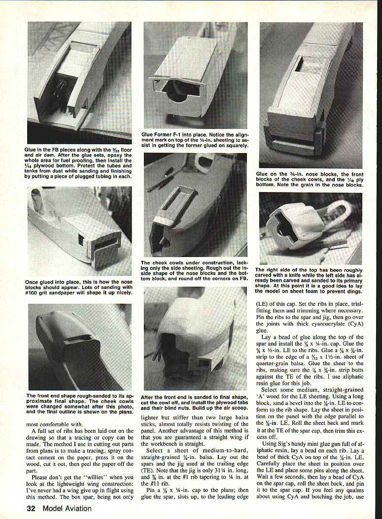
Canopy, Cowling and Cowling Removal
- Glue FB‑1 to FB about 3/8 in. inside the outer curve and glue in place on the sides.
- Glue 3/32‑in. sheet under the smoke tank and glue the 1/8‑in. ply bottom with the vent hole cut per top view. Glue top 3/8‑in. triangles and top 1/4‑in. sheet in place.
- Align F‑1 square with the fuselage using centerlines; glue and add 1/4‑in. medium blocks to the front of F‑1. Shape blocks, tops and sides of check cowls per photos.
- Construct air inlet from 1/32‑in. sheet and sand to shape.
- Cut away removable cowl half using a Zona Saw with care. Install maple blocks and trailing edge ply sheet WMP using epoxy. Epoxy LGB and WMB ply braces making sure WMB is against bottom of WMP.
- Trim the canopy carefully, removing front, back and bottom flange little by little; fit repeatedly to avoid cutting too much.
Assembly
- Mount the wing in the fuselage saddle: sand the wing LE square and remove TE where necessary for proper fit. Align wing square with fuselage, pin firmly, drill holes for 1/4‑20 hold‑down bolts, remove wing, tap maple blocks for 1/4‑20 nylon bolts, and bolt wing back in place.
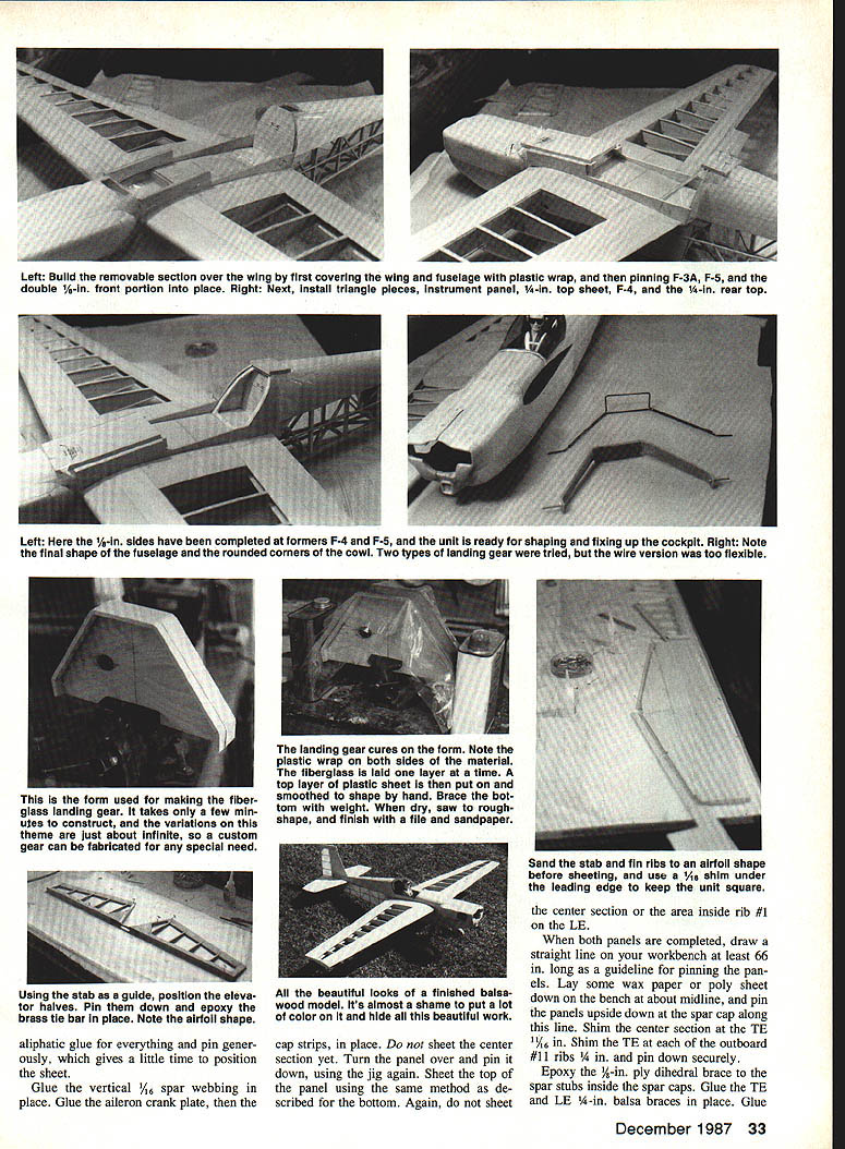
- Lay out the removable top above the wing on 1/8‑in. balsa sheet and fabricate double side portions in front of instrument panel F‑3B per photos. Use ply sheets to cover front F‑3 and rear F‑6 formers and pin/clamp F‑3A to F‑3 and F‑5 to F‑6 before gluing sides and formers.
- Glue former F‑4, glue 1/4‑in. triangle stock to sides flush with the top, and glue top 1/4‑in. sheet to front of cabin section and on top of F‑4 and F‑5. Sand cabin section to match rest of fuselage after installing 1/4‑in. dowels and 4‑40 hold‑down bolts with blind nuts.
- Fix up cockpit to taste. The prototype pilot used a Williams Bros. 2‑1/2‑in. figure with a modified head. For shoulder harness and parachute straps use shoelaces; sunglasses were painted where needed.
Stabilizer, Fin and Control Linkages
- Build stabilizer, elevator, fin and rudder directly over the plans using conventional methods. Sheet the turtledeck with 3/32‑in. A‑grain light balsa for easier curving; wetting the sheet helps form it over formers and stringers.
- Use aliphatic glue for sheeted areas and pin generously to allow positioning time.
- Elevator halves: position using the stab as a guide, pin down and epoxy a brass tie bar in place. Tie bar is 1/8‑in. brass tubing with soldered 1/8‑in. wire arms; epoxy assembly into elevators.
- Glue 1/16‑in. vertical spar webbing, then aileron crank plate and cap strips. Do not sheet center section areas until after wing/center assembly.
Landing Gear
- Two gear types were trialed: double 1/8‑in. music wire and layered fiberglass/epoxy. The wire gear was too springy, so the fiberglass gear was chosen.
- Fiberglass gear method: with the form held in a vise, place layered epoxy‑saturated fiberglass between poly plate sheets, peel from the form and hold against it with heavy objects until cured. Cut strips oversize and use a slow‑setting epoxy. This produces a strong gear with good flex.
Final Assembly Notes
- Install engine using chosen mount; remove fuselage side inside check‑cowl outline to bolt engine and locate throttle pushrod hole. Use plastic tubing for pushrod guides (prototype used outer tube of Gold n' Rod).
- Make up tanks (or multiple tanks if smoking) and install.
- Glue landing gear plate with epoxy and glue bottom 1/4‑in. sheet in place. Glue cross‑grained bottom stringers, then glue 1/8‑in. side stringers and 3/32‑in. fairing strips around aft wing saddle and sand to fair into fuselage.
Finishing
- Cover fuselage up to and including the cabin, rudder and elevator with Supershrink Coverite. Cover the remainder of the fuselage with Sig medium Polyspan using butyrate dope.
- Apply four more coats of dope (one with talc), then spray with polyurethane colors.
- Wing covering: MonoKote aluminum and Coverite Black Baron red plastic heat‑shrink were used on the prototype.
- Lettering and markings:
- Serial letters were made from Sig blank decal sheet sprayed red poly paint, cut to shape, soaked and applied.
- "PRODERA" lettering used Presto Stik vinyl letters (3/4‑in. Helvetica).
- Pilot details: use shoelace bits for harnesses; paint small accessories as needed.
If you choose the Sirius version: leave off the wheel pants and move former F‑4 rearward.
Whichever version you build, if you enjoy an aerobatic performer with the virtuoso capabilities of a full‑size airplane, the TR‑260 is a rewarding model to construct and fly.
Transcribed from original scans by AI. Minor OCR errors may remain.

