
Transmitter Setup Guide
By J.W. Powell
Overview
While today's radios with their adjustments and reversing capabilities have greatly simplified installation problems, they can quickly become confusing when the transmitter is used for more than one model. This simple notebook system takes the struggle out of trying to remember how the radio is set up for each model.
Until recently, RC system parameters, such as the direction and amount of servo throw for a given stick movement, were fixed. We installed the servos and control linkages in each model to conform to the quirks of the RC system. Any changes needed for flight trim or personal preference were obtained mechanically, if at all.
The present generation of RC transmitters, however, allows the user to set up (program) the control channels to suit a particular aircraft. Today, even the simplest sports sets will usually provide servo reversing and total servo-throw adjustment for the primary channels. Many modelers—beginners and experienced alike—own radios that offer one or two adjustments beyond the basics. The more elaborate sets include adjustments for the amount of throw in each direction, the response "law" (linear or exponential), and whether certain channels are to be mixed or slaved. They also have preset controls for several dual-rate switches.
On my Airtronics CS7P transmitter I counted twenty-three settings that could be made before I even began twiddling the sticks, trim controls, rate switches, or rudder-coupling switch. I have not yet lost a plane due to incorrect transmitter setup, but I have come close enough to worry about it. For instance, I use the same transmitter with a power model and a glider. Each model needs quite different servo throws on the various channels. More than once I have found myself trying to fly the glider with wildly oversensitive rudder and elevator response, or the aerobatic power model with barely enough control authority to complete a circuit and land. Luckily, no servo reversing was involved—or I would have experienced backwards control responses as well.
This freedom to customize transmitter parameters is wonderful as long as the equipment is used with only one model and the settings do not get accidentally changed. However, if the same transmitter is used with several models it is nearly certain that flight problems will arise unless one has—and uses—some kind of checklist or reminder notes to verify the correct transmitter setup for the model about to be flown.
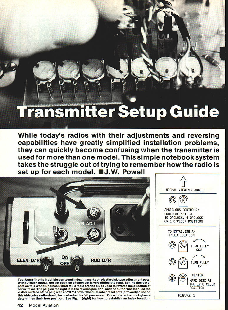
Marking Controls (Top / Above)
Top: Use a fine-tip indelible pen to put indexing marks on plastic disk-type adjustment pots. Without such marks, the set position of each pot is very difficult to read. Behind the row of pots on this World Engines Expert Mk. 9 radio are the plugs used to reverse the direction of servo travel. The plug on the right is in the reverse position; the author has labeled the visible surface of the plug with an "R."
Above: The dual-rate preset pots (arrowed) found on this Airtronics radio should be marked with a felt pen as well. Once indexed, a quick glance determines their true position. See Figure 1 for how to establish an index location.
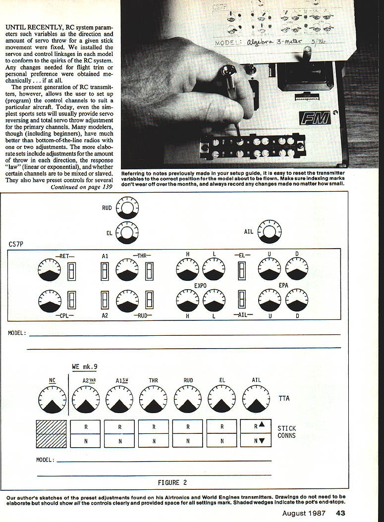
Establishing an Index Location (Figure 1)
Ambiguous controls can appear identical at several settings (for example, they might look the same at 10 o'clock, 4 o'clock, or 1 o'clock). To establish an unambiguous index location:
- Turn the pot fully counterclockwise (CCW).
- Turn the pot fully clockwise (CW).
- Center the pot.
- Mark the disk at the 12 o'clock position with an indelible marker or a dab of paint so the center position is clearly visible.
(Figure 1 illustrates this procedure and the normal viewing angle.)
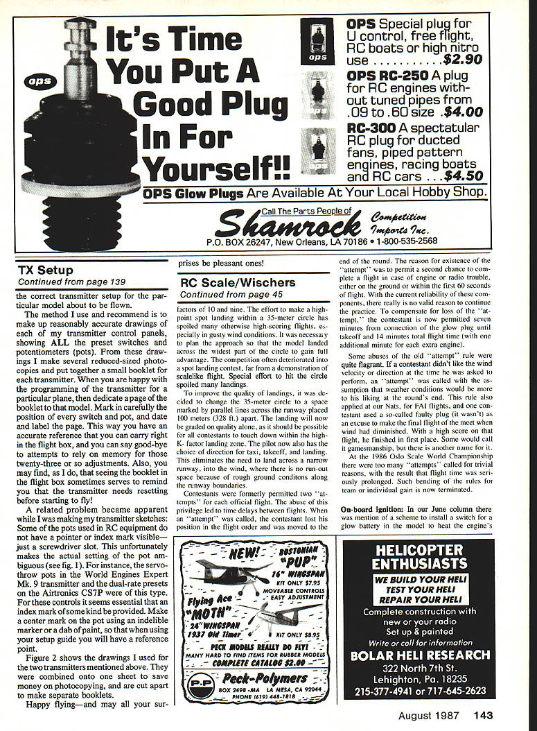
Making a Setup Booklet
The method I use and recommend is:
- Make reasonably accurate drawings of each transmitter control panel, showing all preset switches and potentiometers (pots).
- Make several reduced-size photocopies of each drawing.
- Put together a small booklet for each transmitter.
- When you are happy with the programming for a particular plane, dedicate a page of the booklet to that model.
- Carefully mark the position of every switch and pot on that page, then date and label it.
This way you have an accurate reference that you can carry right in the flight box. You can stop relying on memory for those many adjustments. Seeing the booklet in the flight box may also remind you to reset the transmitter before starting to fly.
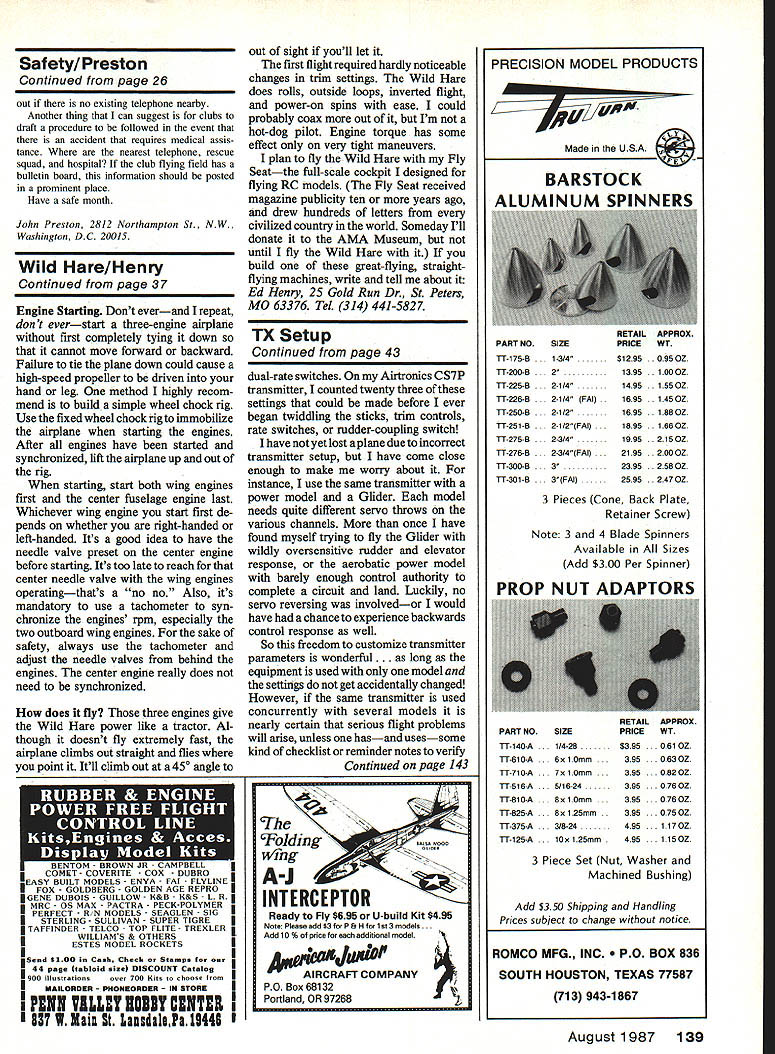
Pot Indexing and Ambiguous Controls (Figure 2)
A related problem became apparent while making my transmitter sketches: some pots used in RC equipment do not have a visible pointer or index mark—just a screwdriver slot. This makes the actual setting of the pot ambiguous. For example, the servo-throw pots in the World Engines Expert Mk. 9 transmitter and the dual-rate presets on the Airtronics CS7P were of this type. For these controls it is essential to provide an index mark of some kind. Make a center mark on the pot using an indelible marker or a dab of paint, so that when using your setup guide you will have a reliable reference point.
Figure 2 shows the drawings I used for the two transmitters mentioned above. They were combined onto one sheet to save money on photocopying and are cut apart to make separate booklets.
Happy flying—and may all your surprises be pleasant ones!
Transcribed from original scans by AI. Minor OCR errors may remain.

